

Page 1
PARTS AND SERVICE MANUAL
FOR
DIMPLEX 26” OUTDOOR
ELECTRIC FIREPLACE
Model DFO2607
Page 2

TABLE OF CONTENTS
OPERATION PAGE 2
PARTS DRAWING PAGE 3
PARTS LIST PAGE 4
WIRING DIAGRAM PAGE 5
FRONT GLASS REMOVAL PAGE 6
UPPER LIGHT REPLACEMENT PAGE 7
LOWER LIGHT REPLACEMENT PAGE 8
MAIN ON/OFF/FLAME CONTROL REPLACEMENT PAGE 9
FLAME ROD AND MOTOR REPLACEMENT PAGE 10
CIRCUIT BOARD REPLACEMENT PAGE 11
AUDIO BOARD REPLACEMENT PAGE 12
1
Page 3
DFO2607
OPERATION
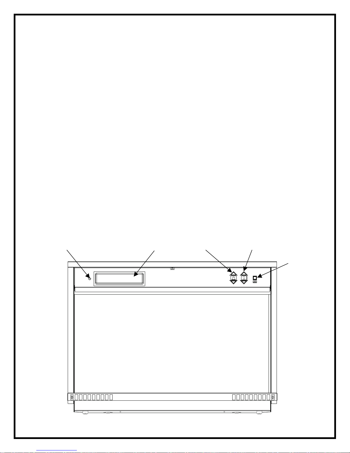
ELECTRIC FIREPLACE MANUAL CONTROL
The manual controls for the firebox are located in the upper right hand corner behind
the access panel. To access the controls, open the upper access panel by pulling
forward and down.
To locate controls refer to Figure 3.
NOTE: The main on/off switch/flame action and flame brightness controls are
always illuminated as long as the unit is plugged in.
A. Main On/Off Switch
The ON/OFF SWITCH supplies power to the flames and over head lights.
B. Flame Action Control
Press the up or down arrow to adjust the flame speed to the desired level.
C. Flame Brightness Control
Press the up or down arrow to increase or decrease the brightness of the over head
lights.
D. Storage Compartment
A convenient location to place your CD’s or MP3 player.
E. Audio Input Plug
Using the audio cord included, a CD or MP3 player may be connected to the firebox.
Figure 3
NOTE: This unit does not have a heat option
Storage Compartment
Flame Action Audio Input Plug
Flame Brightness
Main
On/Off
Switch
2
Page 4
5
6
10
9
11
12
4
3
2
7
1
8
3
Page 5

DFO2607
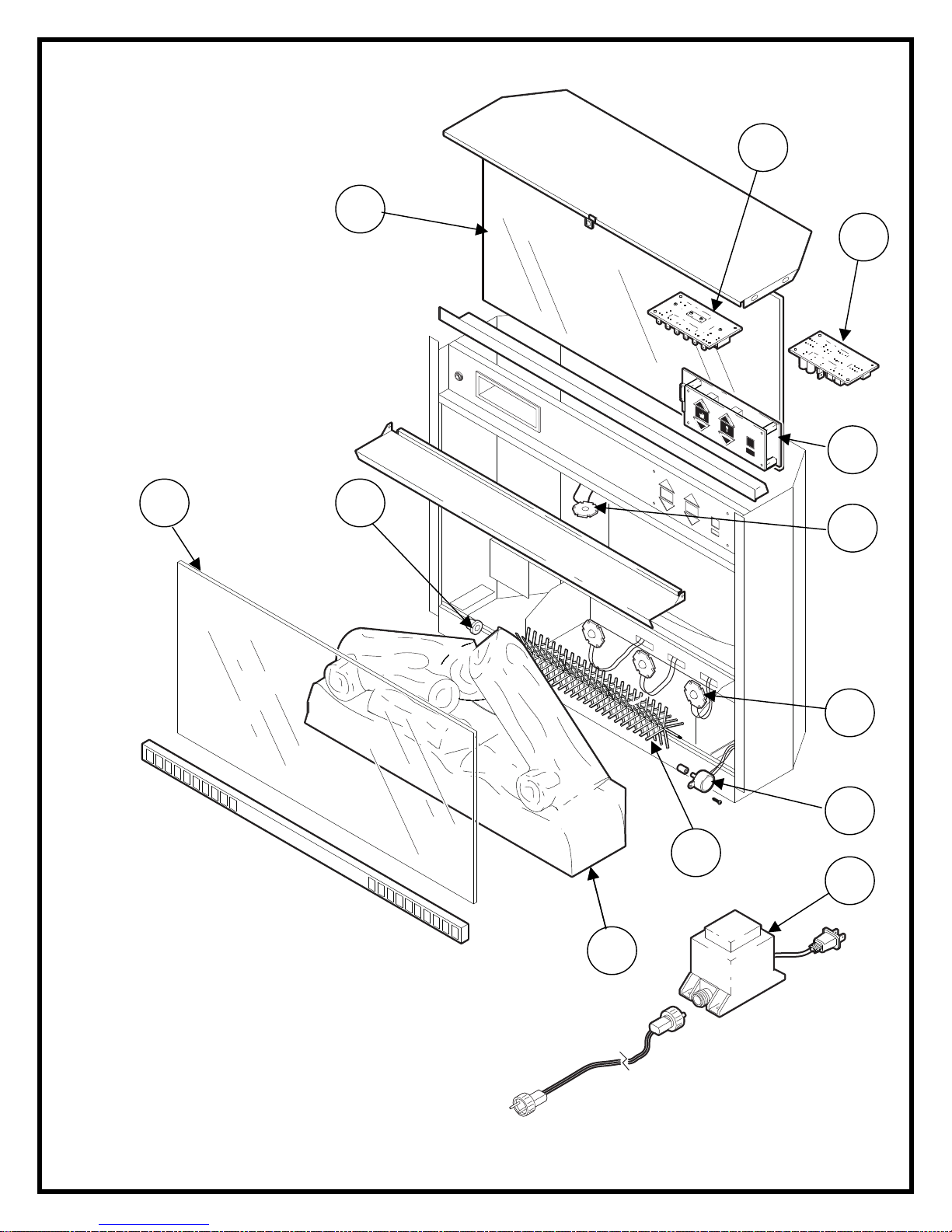
REPLACEMENT PARTS
FIREBOX, 26” – Dimplex
CATALOGUE NO. DFO2607
PART NO. 6903100200
REPLACEMENT PART
1. MOTOR, ASSEMBLY 3000240200RP
2. LED LIGHT, TOP 3700060200RP
3. SWITCHBOARD 3000560100RP
4. CIRCUIT BOARD 3000520200RP
5. MIRROR 5900750200RP
6. GLASS FRONT 5900710200RP
7. LED LIGHT, BOTTOM 3700060200RP
8. TRANSFORMER 2100200200RP
9. FLAME ROD 5900080600RP
10. BUSHING 8500000400RP
11. LOGSET 0437960600RP
12. AUDIO BOARD 3000530100RP
4
Page 6

WIRING DIAGRAM
CONNECTOR,FEMALE
P/N4300430100
(HARNESSINCLUDED)
"B"TERMINAL
TYP.
CONNECTOR,WIRE
TWISTER
4X"A"TERMINAL
MAINPCBBOARD
(BACKSIDEVIEW)
SQUARE
SOLDERPAD
2X"A"TERMINAL
LIGHTWIREHARNESS
AUDIOBOARD
(BACKSIDEVIEW)
5
2500420000
REFERTODWG#
4X"A"TERMINAL
BLACKWIREOFCABLE
TOLINEUPWITHSQUARE
SOLDERPADOFCONNECTORBOARD.
YELLOWWIREOFCABLE
TOLINEUPWITHSQUARE
SOLDERPADOFCONNECTORBOARD.
SPEAKERTERMINAL
INCLUDEDIN
LIGHTWIREHARNESS
1WATTLED
TOPLIGHT
4X"C"TERMINAL
SWITCHBOARD
INCLUDEDIN
LIGHTWIREHARNESS
P/N3000500100
(HARNESSINCLUDED)
1WATTLED
3WATTLED
1WATTLED
FLAMELIGHT
FLAMELIGHT
FLAMELIGHT
FLICKERMOTOR
P/N300240200
(HARNESSINCLUDED)
Page 7

DFO2607
Disconnect power before attempting any maintenance or cleaning to reduce the risk of
electric shock or damage to persons.
Lights need to be replaced when you notice a dark section of the flame. There are
three lights under the log set which generate the flames and embers located under the
emberbed.
It is a good idea to replace all of the lights at one time if they are close to the end of their
rated life. Group replacement will reduce the number of times you need to open the unit
to replace the lights.
FRONT GLASS REMOVAL
1. Remove top from mantel.
2. Lift firebox out of mantel.
3. Lay firebox on it’s back.
4. Remove screws from the left and right side of the front glass lower support.
5. Insert the tip of a slot screwdriver between the glass edge on either the left or right
side trim.
6. Using the screwdriver as a lever, apply pressure in a downward motion forcing the
edge of the glass up.
6
Page 8

DFO2607
Disconnect power before attempting any maintenance or cleaning to reduce the risk of
electric shock or damage to persons.
Lights need to be replaced when you notice a dark section of the flame. There are
three lights under the log set which generate the flames and embers located under the
emberbed.
It is a good idea to replace all of the lights at one time if they are close to the end of their
rated life. Group replacement will reduce the number of times you need to open the unit
to replace the lights.
UPPER LIGHT REPLACEMENT
1. Remove the front glass as shown on page 6 of this manual.
2. Remove the top trim piece by removing the 3 retaining screws.
3. Remove the 10 retaining screws and lift the top off of the unit.
4. Unplug the light wiring harness from the circuit board.
5. Remove the 3 screws and remove the light from the unit.
6. Reassemble in the reverse order.
LIGHT BULB REQUIREMENTS
Quantity of 2 clear chandelier or candelabra bulbs with an E-12 (small) socket base,
60 watt rating.
7
Page 9

DFO2607
Disconnect power before attempting any maintenance or cleaning to reduce the risk of
electric shock or damage to persons.
Lights need to be replaced when you notice a dark section of the flame. There are
three lights under the log set which generate the flames and embers located under the
emberbed.
It is a good idea to replace all of the lights at one time if they are close to the end of their
rated life. Group replacement will reduce the number of times you need to open the unit
to replace the lights.
LOWER LIGHT REPLACEMENT
1. Remove the front glass as shown on page 6 of this manual.
2. Remove the top trim piece by removing the 3 retaining screws.
3. Remove the 10 retaining screws and lift the top off of the unit.
4. Unplug the lower light wiring harness from the circuit board.
5. Remove the flame rod.
6. Remove the 3 screws holding each light and remove the light assembly from the
unit.
7. Reassemble in the reverse order.
8
Page 10

DFO2607
Disconnect power before attempting any maintenance or cleaning to reduce the risk of
electric shock or damage to persons.
MAIN ON/OFF SWITCH REPLACEMENT
1. Remove the front glass as shown on page 6 of this manual.
2. Remove the top trim piece by removing the 3 retaining screws.
3. Remove the 10 retaining screws and lift the top off of the unit.
4. Locate the main on/off/flame control mounted on the top panel and disconnect the
wiring plug noting it’s original location.
5. Remove the 4 mounting screws on the front of the top panel and remove the control
from the unit.
6. Reassemble in the reverse order.
9
Page 11

DFO2607
If unit was operating prior to servicing allow at least 10 minutes for light bulbs and
heating element to cool off to avoid accidental burning of skin.
Disconnect power before attempting any maintenance or cleaning to reduce the risk of
electric shock or damage to persons.
FLAME ROD AND MOTOR REPLACEMENT
1. Remove the front glass as shown on page 6 of this manual.
2. Remove the top trim piece by removing the 3 retaining screws.
3. Remove the 10 retaining screws and lift the top off of the unit
1. Remove the reflector rod from the flame motor by pulling the end of the rod to the
left and carefully remove flame rod from rubber sleeve.
4. Remove the 2 screws securing the flame motor to the flame motor bracket
5. Disconnect motor wiring connections form circuit board.
6. Discard the old motor.
7. Reassemble in the reverse order as above.
10
Page 12

DFO2607
If unit was operating prior to servicing allow at least 10 minutes for light bulbs and
heating element to cool off to avoid accidental burning of skin.
Disconnect power before attempting any maintenance or cleaning to reduce the risk of
electric shock or damage to persons.
TO REPLACE THE CIRCUIT BOARD
1. Remove the front glass as shown on page 6 of this manual.
2. Remove the top trim piece by removing the 3 retaining screws.
3. Remove the 10 retaining screws and lift the top off of the unit.
4. Locate the circuit board on the underside of the top cover.
5. Remove wiring connections from circuit board noting their original locations.
6. From under the top panel, break off the six mounting studs on the circuit board by
grasping with pliers and twisting on the protruding part of the stud, push the
remainder of the studs out through the top panel.
NOTE: New mounting studs are supplied with the replacement circuit board.
7. Properly orientate the new circuit board and connect all of the wiring connections
11
Page 13

DFO2607
If unit was operating prior to servicing allow at least 10 minutes for light bulbs and
heating element to cool off to avoid accidental burning of skin.
Disconnect power before attempting any maintenance or cleaning to reduce the risk of
electric shock or damage to persons.
TO REPLACE THE AUDIO BOARD
1. Remove the front glass as shown on page 6 of this manual.
2. Remove the top trim piece by removing the 3 retaining screws.
3. Remove the 10 retaining screws and lift the top off of the unit.
4. Locate the audio board on the underside of the top cover.
5. Remove wiring connections from audio board noting their original locations.
6. From under the top panel, break off the six mounting studs on the audio board by
grasping with pliers and twisting on the protruding part of the stud, push the
remainder of the studs out through the top panel.
NOTE: New mounting studs are supplied with the replacement audio board.
7. Properly orientate the new circuit board and connect all of the wiring connections
12
 Loading...