

Dimmex 24-1, 12-2 User Manual
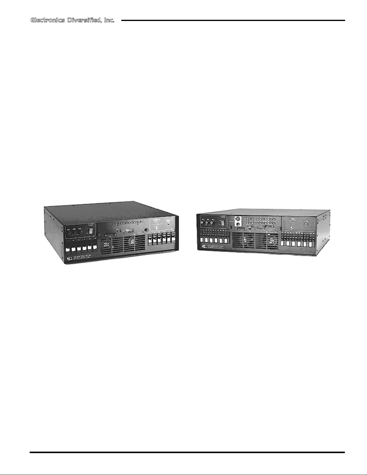
Dimmex
TM
M-L
DIMMEX
w/Multi-Link
(and/or Analog)
Dimmex 12-2
TM
TM
Dimmex 24-1
Revision 3, September, 1998
©1998, Electronics Diversified, Inc.
User Manual
070-0540
1
Dimmex
TM
M-L
Introduction
This User's Manual is supplied with your Dimmex. Copies of
this manual may be obtained from Electronics Diversified, Inc.,
for a nominal charge. It is recommended that you copy those
portions of this manual applicable to your present use in the
installation, maintenance or repair and preserve the original in a
safe place.
Copyright 1998, by Electronics diversified, Inc. All rights
reserved.
No part of this Manual may be reproduced by any means,
graphic, electronic, or mechanical, including photocopying,
recording, taping, or information storage and retrieval systems,
without the express written permission of Electronics Diversified,
Inc., except in connection with installation, repair and maintenance
of installed *DimmexTM Dimmer Packs.
Table of Contents
Description . . . . . . . . . . . . . . . . . . . . . . . . . . . . . . . . . . . . . . . . 2
Front Panel . . . . . . . . . . . . . . . . . . . . . . . . . . . . . . . . . . . . . . . 3
Rear Panel . . . . . . . . . . . . . . . . . . . . . . . . . . . . . . . . . . . . . . . 4
Input Power Wiring . . . . . . . . . . . . . . . . . . . . . . . . . . . . . . . . . . 4
Three-Phase Wiring . . . . . . . . . . . . . . . . . . . . . . . . . . . . . 4
Single-Phase Wiring . . . . . . . . . . . . . . . . . . . . . . . . . . . . . 4
Input Control Connections . . . . . . . . . . . . . . . . . . . . . . . . . . . . 5
Analog Control . . . . . . . . . . . . . . . . . . . . . . . . . . . . . . . . . 5
Analog Connector . . . . . . . . . . . . . . . . . . . . . . . . . . . . . . . 5
Analog Wiring Connections . . . . . . . . . . . . . . . . . . . . . . . .5
Multiplex Control . . . . . . . . . . . . . . . . . . . . . . . . . . . . . . . . 5
Dimmer Pack Address Table. . . . . . . . . . . . . . . . . . . . . . . 5
*Multi-Link Connectors. . . . . . . . . . . . . . . . . . . . . . . . . . . . 6
USITT DMX-512 Digital Multiplex . . . . . . . . . . . . . . . . . . . 6
USITT AMX-192 Analog Multiplex . . . . . . . . . . . . . . . . . . . 6
*Fiber-Link Optical Multiplex . . . . . . . . . . . . . . . . . . . . . . . 6
Multiplex Cables . . . . . . . . . . . . . . . . . . . . . . . . . . . . . . . . 6
Self Test . . . . . . . . . . . . . . . . . . . . . . . . . . . . . . . . . . . . . . . . . . 6
Dimmer Output Test . . . . . . . . . . . . . . . . . . . . . . . . . . . . . . . . . 6
Lamp Preheat . . . . . . . . . . . . . . . . . . . . . . . . . . . . . . . . . . 6
Calibration . . . . . . . . . . . . . . . . . . . . . . . . . . . . . . . . . . . . . . . . 7
Wall Mounting . . . . . . . . . . . . . . . . . . . . . . . . . . . . . . . . . . . . . 7
Dimmer Phasing Table . . . . . . . . . . . . . . . . . . . . . . . . . . . . . . 7
Solid-State Relay Replacement . . . . . . . . . . . . . . . . . . . . . . . . 8
Troubleshooting Guide . . . . . . . . . . . . . . . . . . . . . . . . . . . . . . 9
Service . . . . . . . . . . . . . . . . . . . . . . . . . . . . . . . . . . . . . . . . . . 9
Registration . . . . . . . . . . . . . . . . . . . . . . . . . . . . . . . . . . . . . . 10
Description
The Dimmex Multi-LinkTM dimmer pack is a compact lighting
control system providing twelve 2400 watt, or twenty-four 1200
watt, solid-state dimmers. With the Multi-Link control module, a
variety of control formats are supported.
It is recommended that you read the following instructions
before operating your dimmer pack for the first time.
Location: Although very efficient, solid-state dimmers
generate heat . Be sure a free flow of air is
allowed through the ventilation openings on the
front and rear of the cabinet. Locate the dimmer
pack close to the power source. Either avoid
long power cable runs or increase the input
power wire size.
Dimmer Type: This dimmer is designed to properly dim 120VAC
incandescent or quartz lamps. Low voltage
lamps operated through a standard (nonelectronic) transformer with a 120VAC primary
may also be operated. Do Not connect any
other type of load such as motors or fluorescent
lamps to this dimmer.
Power Source: This dimmer is designed to operate on 120
volts, 60Hz, AC power. This dimmer should be
connected to a molded-case circuit breaker
properly sized for the load.
Supply Cord: The dimmer power cord is not supplied. Refer
to the INPUT Power Wiring section for proper
wiring.
CAUTION:
TO PREVENT THE RISK OF ELECTRICAL SHOCK. DO
NOT REMOVE COVER. NO USER SERVICEABLE
PARTS INSIDE. REFER SERVICING TO QUALIFIED
SERVICE PERSONNEL.
Do not connect this Dimmer to other than the specified voltage,
or to direct current.
WARNING:
Maximum ambient operation and storage environment for this
equipment is 104°F (40°C), with 90% humidity, noncondensing. Extreme caution is advised when having liquids,
food and cigarettes around any equipment. During severe
electrical storms, equipment should be disconnected. Failure
to adhere to these requirements may result in malfunction or
serious damage.
TO REDUCE THE RISK OF FIRE OR ELECRICAL SHOCK,
DO NOT EXPOSE THIS UNIT TO WET LOCATIONS.
*Dimmex, Multi-Link, and Fiber-Link are registered trademarks of Electronics Diversified, Inc.
2
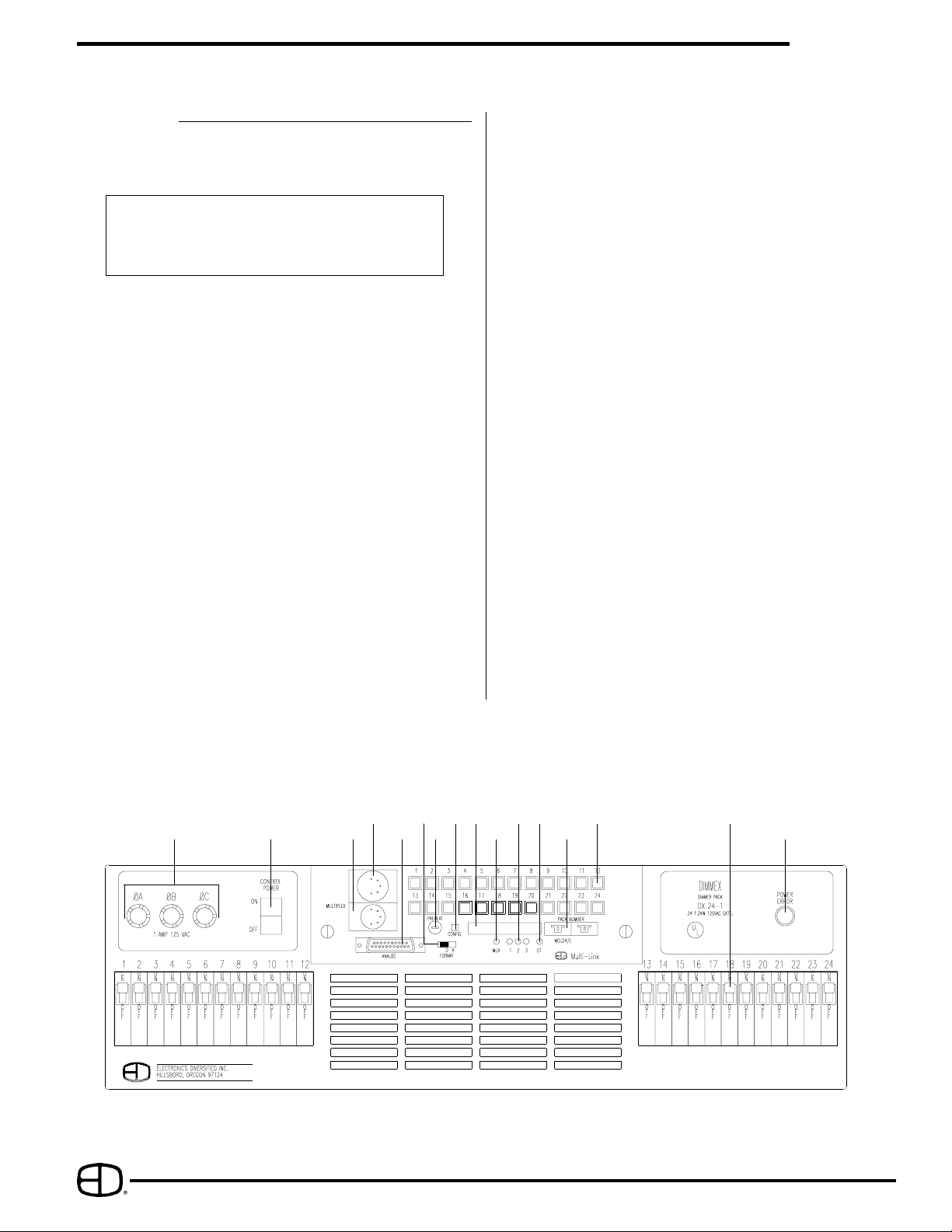
Front Panel
1. Input Power Error Indicator:
This indicator will light if there is voltage between the
neutral conductor and the dimmer chassis.
IMPORTANT!
If this indicator is on, disconnect power immediately
and check for improper input power wiring. Refer to
the INPUT POWER WIRING section.
2. Dimmer Circuit Breakers:
One fully magnetic circuit breaker is supplied for each
dimming circuit. Turn off the corresponding breaker when
re-lamping or connecting loads.
3. Control Power Switch:
Turn on this switch to power the control electronics. When
this switch is off, the dimmer will not respond to any external
control signals and the dimmer preheat is off.
4. Power Indicators:
These green indicators will light when power is applied to
the corresponding phases. All three indicators should light
on three-phase dimmers, and indicators 1 and 3 should light
on single-phase dimmers.
5. Control Power Fuses:
These three fuses protect the Multi-Link control module.
6. Dimmer Output Test Buttons & Status Indicators:
Each yellow indicator will light as bright as the output of
that individual dimmer. When the button is pressed in, the
corresponding dimmer will be forced to full output and the
yellow indicator will be at maximum brightness.
7. Analog Control Input:
Connect the analog cable from an analog 0- +10 Volt
controller here.
Dimmex
8. Multiplex Signal Format Switch:
Set this switch to "D" for USITT DMX-512 digital, or "A" for
AMX-192 control formats.
9. Dimmer Pack Number:
These two thumbwheel switches select the dimmer pack
address for multiplexed dimmer formats.
10. Configure Button:
This pushbutton is used to enter new multiplex data formats,
self-test patterns, or different dimmer pack addresses. Press
this pushbutton after any change is made in multiplex data
formats, self-test patterns, or dimmer pack addresses.
11. Multiplex control Input:
Connect the multiplex cable from the control console here.
12. Multiplex Control Output:
This connector is paralleled to the Multiplex Control Input
connector. Use this connector to add additional dimmers.
13. Multiplex Signal Presence Indicator:
The yellow indicator lights when a valid multiplex signal is
received.
14. Dimmer Overtemp Indicator:
This red indicator will light when the dimmer pack is shut
down due to an over-temperature condition. The dimmer
pack will re-energize when it has cooled down to an
acceptable temperature.
15. Preheat Level:
This control is used to set the preheat level of the lamps.
Turn it clockwise to increase the preheat level.
16. Calibration Access Plate:
Removal of this plate allows access to calibration
potentiometers and test points. Refer to Calibration section.
TM
M-L
5
1 AMP 125 VAC
3
1210
11715
168
H 1 2 3 H 1 2 3 GND
14
13
3
6 4
9
2
1
 Loading...