

DIMLUX MAXI CONTROLLER EVO 1.2 Installation And User Manual
EN
LET THERE BE LIGHT
DIMLUX
DIMLUX.NL
® DimLux is a registered trademark of
airSupplies
MAXI CONTROLLER EVO 1.2
Installation and User Guide
2 3
ENEN
INTRODUCTION INSTALLATION
The Dimlux maxi controller is a modular control system for operating and monitoring the Dimlux lighting, CO2 and
VPD. The EVO controller is available with and without USB log function. The controller also has a thermostat/hygrostat
function (AUX) and can also control a fan.
A maximum of 160 Dimlux light xtures or pre-selector devices can be controlled by means of two out-ports. The
controller switches the lighting on or off by means of a built-in timer. If a set temperature is exceeded, the lighting dims
automatically or – if necessary – switches off half or all light xtures off. A switchboard with timer/relay/reducers is
not necessary.
Besides lighting, the controller can also regulate the CO2 level in an air-conditioned room. A very accurate dual-beam
CO2 sensor can be used to control CO2 generators, cold CO2 installations and ventilation systems for air replacement.
On the AUX port of the EVO 1.2, an “auxbox” can be used to connect a humidier or a dehumidier, a heating system
and even a ventilator. Various parameters can be read and regulated in a VPD environment. The screen shows the
ambient temperature, relative humidity, plant temperature and VPD. The DATALOG function can be used to store all
values on a USB stick. The controller writes all measured values onto the stick every minute and these can be read off
later in graphic form on a PC.
The controller can also operate the lighting in two rooms in turns. This requires a second temperature sensor, which
can be connected to port RH/T2. The relative humidity sensor will no longer be required. The controller is modular: All
sensors can be purchased independently according to need.
Components
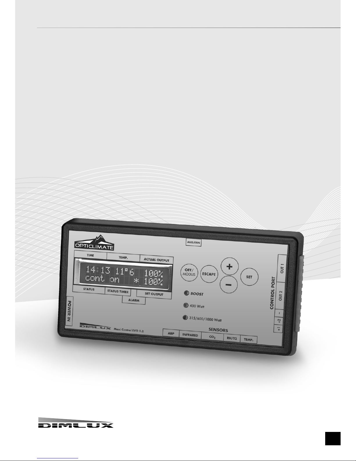
The controller
The controller regulates and operates the lighting, CO2, VPD status and any other
connected components (AUX).
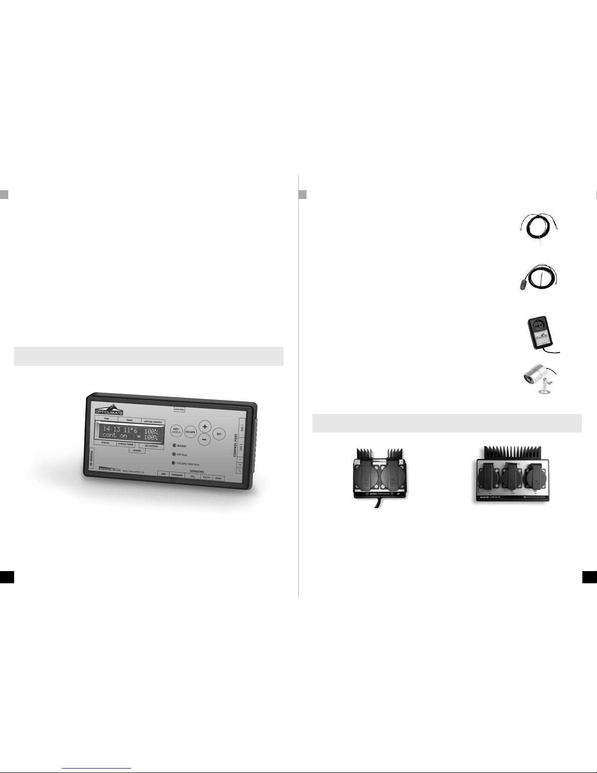
Temperature sensor
The temperature sensor measures the room temperature and should be protected
against light (shaded). A cardboard cover is sufcient.
RH% sensor
The RH% sensor measures the relative humidity in the room. This is necessary to
determine the VPD or to control a humidier or a dehumidier. The RH% sensor should
also hang in the shade.
CO2 sensor
You can read and control the current CO2 level in a room using a very accurate dual-
beam CO2 sensor. The sensor can control a CO2 generator or a cold CO2 installation.
PT camera
The temperature of a crop can be measured using the plant temperature camera.
This temperature provides an indication of the vaporization of the crop.
The camera is also needed to determine the VPD.
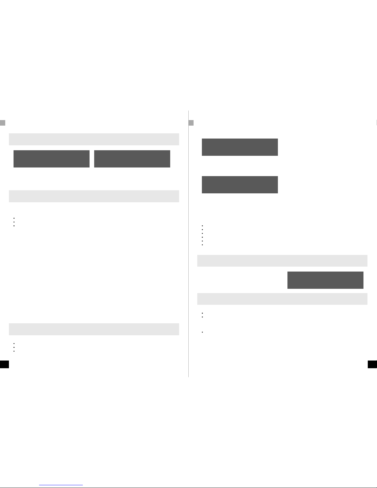
The Auxbox
Auxbox Auxbox fan
An auxbox can be connected to controller’s aux port. The auxbox converts the maxi controller into a fully automatic
air conditioning system. The auxbox is available in two designs. The auxbox has two connections, one for a heating
system/heater and two for a humidier or dehumidier. The other design can also control a fan as well as a heating
system and a humidier and a dehumidier. The fan control is electronic and has no annoying buzz.

4 5
ENEN
CONNECTIONS CONNECTIONS & MENU
Connecting the lighting ( Also see the other connectivity options on pages 19 & 20 )
The controller communicates with the Dimlux ballasts or the light xtures by means of a signal cable, which should be
connected between the controller and the various ballasts and light xtures. Interlink cables are supplied with both the
Maxi-controller and the ballasts/ light xtures. Separate Interlink cables can be ordered in different lengths. Ask your
dealer for more information.
Interlink cables
There are 2 ports for Interlink cables, namely OUT 1 and OUT 2, on the side of the controller. Up to 80 ballasts or light
xtures may be connected to each port, which means that in total, 160 ballasts or light xtures can be connected as
long as the original Dimlux Interlink cables are used.
Interlink cables (UTP)
There are two ports on the ballasts or light xtures, on which the Interlink cables are connected. The port on the Maxi
Controller (out 1 and/ or out 2) is connected to port A of the ballast or light xture. Port B is now connected to port A
of the ballast or light xture via an Interlink cable. The sequence is therefore controller-out> port A, then from B to A /
B to A / B to A etc. A is therefore the input signal and B is the output signal.
At high temperature safeguard, ballasts or light xtures will now switch off alternately. Thus, it is not (no longer) required
to connect the signal wire alternately. The electronics in the ballasts or light xtures regulate this independently.
There is a green plug with three terminals +1, +2 and - (minus), under the 2 OUT ports. This connection can be used to
control older types of ballasts or light xtures without Interlink.
The ABP jack enables the connection of a 2nd Maxi Controller. The two controllers then work together on 1 clock /
timer in the master / slave conguration. Master-slave copy or invert should be selected in the 2nd controller, using
the mode button. The 1st controller is set to the normal function (on / off / timer / countdown) using the mode button.
double-core cables
Older models ballasts or light xtures without Interlink connections can also be controlled with the EVO 1.2. The green
connector beneath the OUT ports can be used for this. Here, up to 40 ballasts or light xtures can be connected per
port. (80 in total)
double-core cable to following ballast >< to following ballast
The controller is connected to the ballasts or light xtures using a double-core cable. On the controller, you can choose
for port +1 and - (minus), for instance. This is then connected to + and - on the ballast or light xture. If there is more
than one ballast or light xture, the double-core cable can be looped in series from the rst ballast/light xture to the
next one. Always + to + and - to -.
When installing multiple ballasts / light xtures, this should always be distributed over port +1 and port +2. In case of
a high temperature safeguard, port +2 switches off.
Connecting the CO2
The dual-beam CO2 sensor can simply be plugged into a wall socket.
The long cable including the plug is inserted into the port with the CO2
indication.
Now you can connect the CO2 generator or pressure-reducing valve to
the CO2 sensor.
Connecting the auxbox
The fan/ auxbox is easily connected to an existing wall socket. The 5m
communication cable is connected to the aux port via the plug. Now the
apparatus for controlling the box must be inserted into the correct port.
Connecting the VPD
To be able to determine the VPD value, the temperature sensor,
RH% sensor and PT camera should be connected to the controller.
Both the temperature sensor and the RH% sensor should be covered
against the incidence of light. A cardboard cover is sufcient.
The PT camera should be mounted in such a way that it “illuminates” the crop
under an angle of approx. 45º without measuring walls, reectors or other
parts of the room as well. A circle with a diameter of 50 cm is measured if the
distance to the crop is 50 cm. The circle is 80 cm if the distance is 80 cm.
6 7
ENEN
MENU & KEYS MENU & KEYS
Basic Advanced Menu
Using
Advanced menu
Using
Basic menu
The controller has a basic and an advanced menu. This enables a very easy operation without the need to go through
the parameters that were set earlier. The basic menu only shows the most frequently used functions. All parameters can
be changed and set in the advanced menu. You can switch between the basic and the advanced menus by holding
down the SET key.
Basic keys
OFF/MODE
By pressing briey and repeatedly on the OFF/MODUS key, you can select:
Lights permanent off > Lights are permanently off.
Lights permanent on > Lights are always on.
Lights by timer on/off > Lights go ON/OFF using the timer.
There are also two short cut keys available:
When you press the MODEkey rst and then the MIN (–) key, the “Lights permanent off” starts to operate immediately.
If you press the PLUS (+) key after the MODE key, the “Lights permanent on” starts to operate immediately.
ESCAPE
By pressing briey and repeatedly on the ESCAPE key, you can select to show:
*LIGHT The current time, room temperature, light output and remaining time are displayed.
*CO2 The current and set CO2 value are displayed.
*AUX/FAN The current temperature and the set fan speed are displayed.
*VPD. The plant temperature, room temperature, relative humidity and the VPD are displayed.
Using the ESCAPE key will also enable you to leave the menu.
PLUS (+)
You can browse or increase the values by pressing this key briey and repeatedly.
MIN (-)
You can browse or decrease the values by pressing this key briey and repeatedly.
SET
Using this key, the menu is opened in order to change settings.
Basic light menu
The following parameters can be set in the basic light menu:
Current time
Timer ON/OFF
Type of ballast/light xture
Time
Time
05:51
Press the SET key briey: the current time will appear. By pressing the SET key again, the time can be set using the +
or – key. Pressing the ESCAPE key will return you to the Home screen.
Timer ON/OFF
Timer on/off
8:00 till 20:00
Press the SET key shortly and navigate through the menu using the + or – key, until ‘Timer ON/OFF’ appears on the
screen. Pressing the SET key again will allow you to set the ON and OFF times.
Type of ballast/light xture
Press the SET key briey and navigate through the menu using the + or – key, until “output-power” appears on the
screen. By pressing the SET key again, you can select by using the + or – key which light xture you wish to control:
315 Watt (CDM lamp)
400watt (hps of hpi)
600watt (hps/niet EL) ook wel 230volt lamp genoemd
600watt EL UHF (hps/EL UHF) ook wel 400volt lamp genoemd
630watt DUAL (2x315watt cdm)
1000watt EL UHF Ook wel 1000watt double ended genoemd
Basic CO2 menu
If you press the SET key in the CO2 screen, you can calibrate the
CO2 auto calibrate
# 0.0 °C
sensor automatically. By pressing the SET key again, you
can select Auto Calibrate Yes of No. If you want to calibrate
the sensor, it should be placed in outdoor air for ve minutes
and then press Auto Calibrate/Yes.
Basic Aux/ Fan menu
The following parameters can be set in the basic fan menu:
Fan mode
Temperature
Press SET to change these parameters. Fan mode can be used to choose between the following options:
Temperature > The fan works faster if a certain temperature is reached.
The temperature mode can be used to set the temperature at which the fan must work faster.
 Loading...