

Page 1

Page 2

Page 3

Export Sonic Immersion System
Table of Contents
OWNER’S MANUAL ......................................................................... 1
FEATURES OF THE SONIC IMMERSION .................................................1
USING THE CD PLAYER ...................................................................... 1
DEALER INSTALLATION .............................................................. 2
GETTING READY TO START ................................................................ 3
Overview of the Installation........................................................... 3
Required Tools............................................................................... 3
Parts List........................................................................................ 5
REMOVING PANELS ............................................................................ 8
Remove Equipment Compartment Panel ....................................... 8
Remove the Sub Woofer Compartment Panel.............................. 10
INSTALLING THE SUB WOOFER COMPARTMENT ...............................13
PRE WIRING FROM EQUIPMENT COMPARTMENT TO SUB WOOFER
COMPARTMENT ................................................................................ 19
INSTALLATION OF POWER SUPPLY ................................................... 25
Pre-Wire Power Supply ............................................................... 25
Installing Power Supply in Equipment Compartment.................. 28
Wiring the Power Supply .............................................................30
Determining Location of CD Weather Cover .............................. 32
Cutting Panel Hole for CD Player Door Assembly ..................... 33
Installation of CD Player Door and Bezel................................... 37
Installation of Panel and CD Player............................................38
INSTALLING THE SATELLITE SPEAKERS ............................................40
Installing the Satellite Speaker Wires.......................................... 42
SECURING THE AMPLIFIER................................................................ 47
COMPLETE THE INSTALLATION......................................................... 47
iii
Page 4

Export Sonic Immersion System
iv
Page 5

Export Sonic Immersion System Dealer Owners Manual
Owner’s Manual
Features of the Sonic Immersion
• Dealer installation allows you to add to any Sonic Immersion
System ready Dimension One Spa in stock
• Patented planar magnetic speaker technology (1/4” [6.35 mm]
thick) that generates unparalleled sound quality even in the
harshest environmental conditions
• Superior fidelity and low distortion
• Articulated speaker mount that allows multidirectional
capability and if the speakers are struck by an object,
speakers deflect without being damaged
• Remote operation
Using the CD Player
The manufacturer of the Sonic Immersion System CD Player has
supplied a User Guide for the CD player. Please refer to this guide for
instructions on how on use of the CD player.
1
Page 6
Export Sonic Immersion System Dealer Installation Guide
Dealer
Installation
This section intended for use by authorized dealer personnel only
2
Page 7

Export Sonic Immersion System Dealer Installation Guide
Getting Ready To Start
The Sonic Immersion System can only be installed on spas with the
following serial numbers.
Table 1 Sonic Immersion System Ready Spas
Model Serial Number
Aurora HP 91275 or higher
Aurora II 91210 and higher (Also 91184)
Aurora XLT 91295 and higher
Caliente HP 91301 and higher (Also 91290 and
91299)
Californian 91198 and higher
Chairman 91245 and higher
Chairman II 91234 and higher
Diplomat 91197 and higher
Nautilus 91458 and higher (Also 91455)
Triad 91372
Triad II 91625 an higher (Also 91567)
Overview of the Installation
The installation of the Sonic Immersion System is a simple process
that includes removing the spa skirt, drilling a few holes using the
templates provided to guide you, and then connecting one or more
power cables. This guide is provided to help complete this task in a
quick and efficient manner.
Required Tools
You will need the following tools to complete the installation:
3
Page 8
Export Sonic Immersion System Dealer Installation Guide
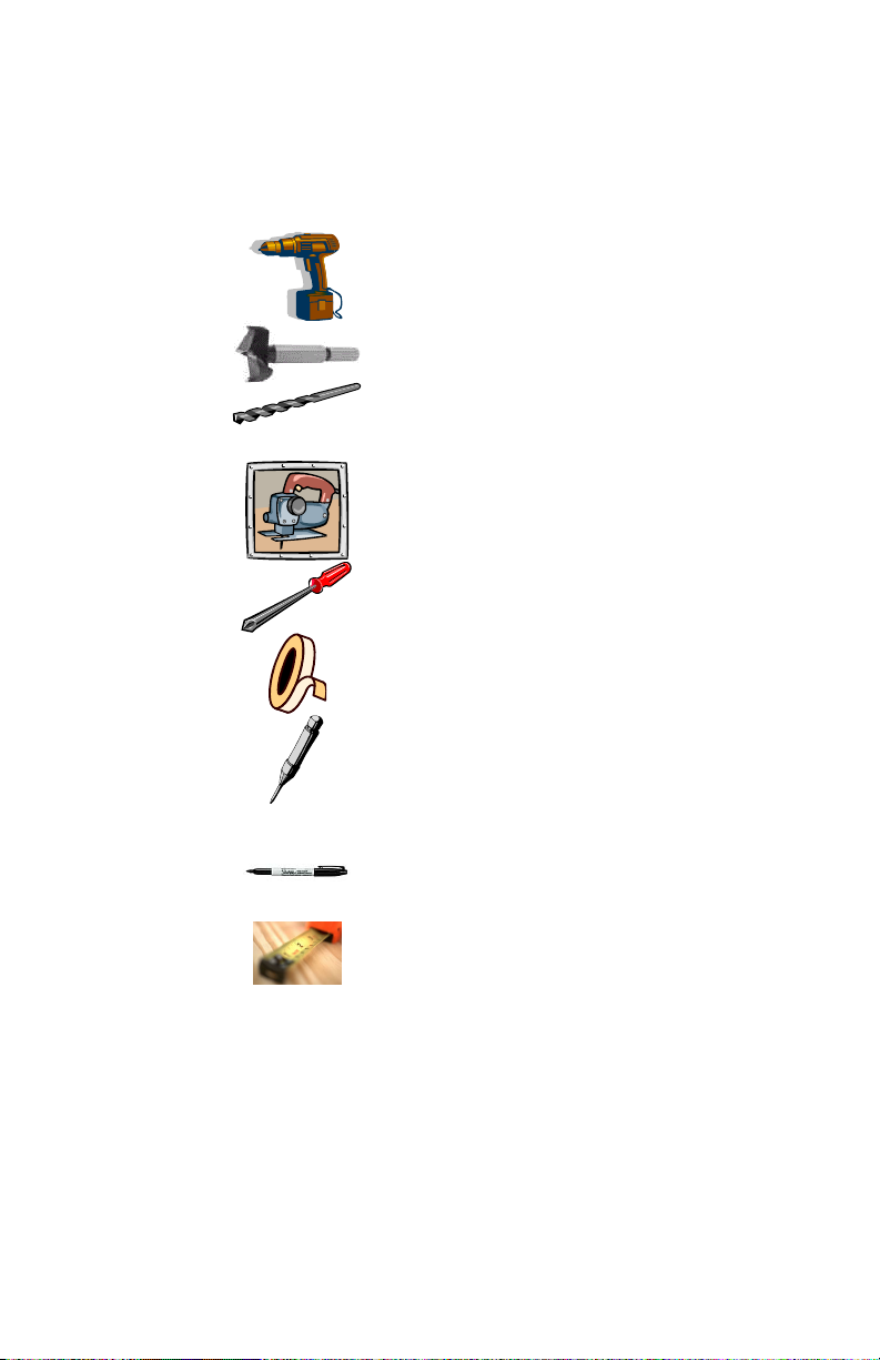
Table 2 Required Tools
Electric drill
1 ½ inch (3.8 mm) hole saw
¼ inch (6.35 mm) drill bit
3/8 inch (9.5 mm) drill bit
Saber Saw
Phillips screwdriver
Tape (masking, electrical, duct, or
packaging) ½ in (12.7 mm) width
Spring-loaded punch
(or other tool(s) that can be used to
mark drilling locations, such as a
hammer & nail)
Fine Point Marker
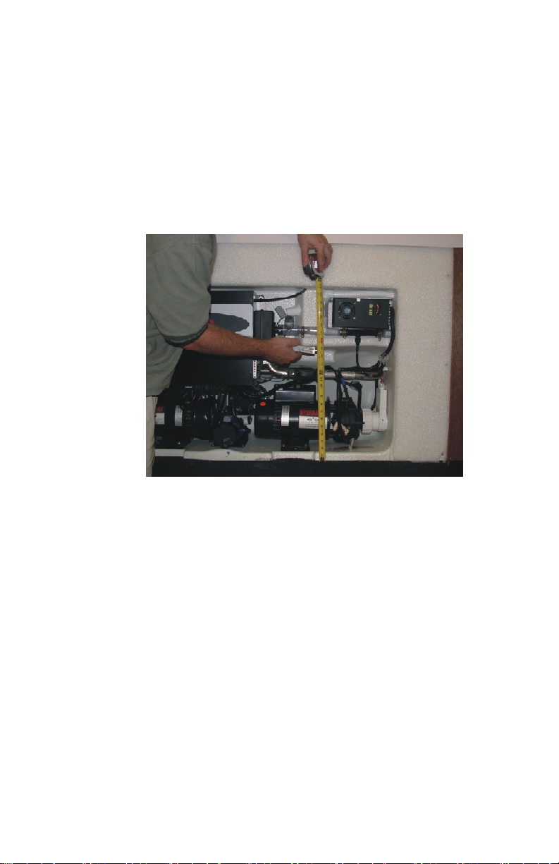
Measuring Tape
Fish Tape
Fish Tape Lubricant
Non Ratcheting PVC Pipe Cutter
4
Page 9

Export Sonic Immersion System Dealer Installation Guide
Medium Size Needle Nose Pliers
Wire Stripper
Utility Knife
5/16” (7.94 mm) Nut Driver or wrench
Six inch (15.24 cm) square
Stapler and Staples
Straight Edge
Safety Glasses
Silicone caulking (clear)
Small Saw
Parts List
You should have received the following parts in the Sonic
Immersion System installation kit:
5
Page 10
Export Sonic Immersion System Dealer Installation Guide
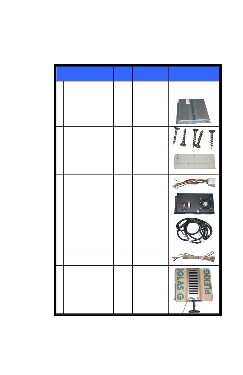
Table 3 Parts List
Description Qty Item
Number
This document 1 01510-
1030
Amplifier 1 01564-08
Coarse-
5 01051-06
Threaded
Drywall Screws
Template 1 Doc 74-
Rev A
Power Supply
1 01564-19
Harness
Power, supply,
1 01564-01
stereo
Main Harness 1 01564-20
Speaker, lead 2 01564-21
Speakers,
Satellite
2 01564-14
6
Page 11
Export Sonic Immersion System Dealer Installation Guide
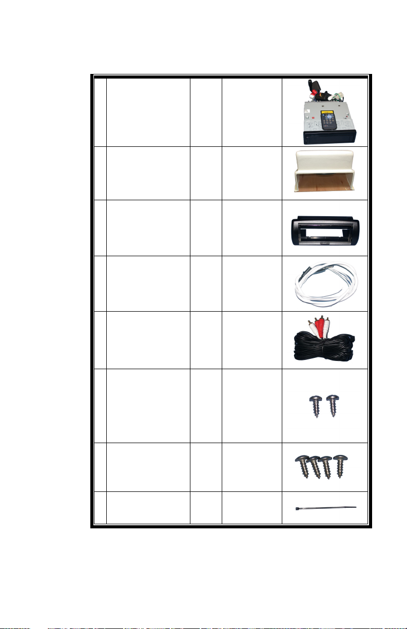
Stereo 1 01564-03
Sub-woofer sub
assembly
Stereo cover,
marine
Dual pole
antenna
Preamp stereo,
cable
Power supply
screw, sheet
metal, SS, PH
Marine cover
screws, #8 x ½”
(1.3 cm) SS
Truss Head
Cable Ty, 4”
(10.2 cm) black
1 01564-09
1 01564-04
1 01564-05
2 01570-24
2 01011-38
4 01011-40
10 01200-006
7
Page 12
Export Sonic Immersion System Dealer Installation Guide
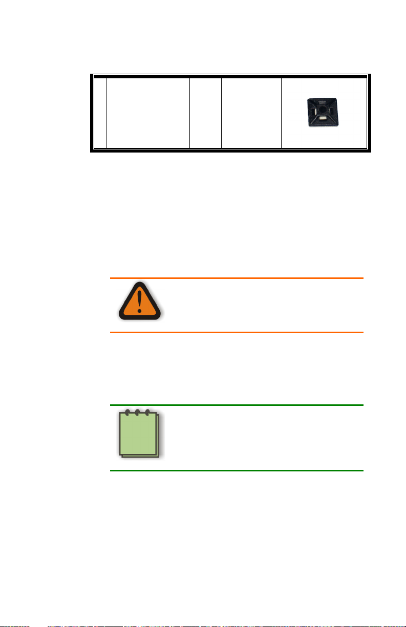
Cable Ty Mount 10 01200-005
Removing Panels
In order to install the system up to three panels must be removed
from the spa: the equipment compartment panel, the panel where the
sub woofer is installed, and the panel where the Satellite Speakers are
to be installed.
Remove Equipment Compartment Panel
Possible Electrical Shock Hazard
Warning
1. Turn off the main spa circuit breaker located in the
disconnect box or house panel.
2. Verify that all power has been turned off before continuing
installation.
Refer to the Spa Service Manual to
determine how to confirm that all
power to the spa has been turned off.
Note
3. Locate the spa’s Main Top Side Control, Figure 1.
8
Page 13

Export Sonic Immersion System Dealer Installation Guide
Figure 1. Top Side Control
4. The Lower Control is located in the equipment compartment
behind the spa panel below the Main Top Side Control.
5. Use the screwdriver to remove the equipment compartment
panel screws, Figure 2.
Figure 2. Equipment Compartment Panel Screws
9
Page 14

Export Sonic Immersion System Dealer Installation Guide
The number of screws to be removed will depend on
the model of spa.
Note
Remove the Sub Woofer Compartment Panel
The installation location of the sub woofer compartment will vary
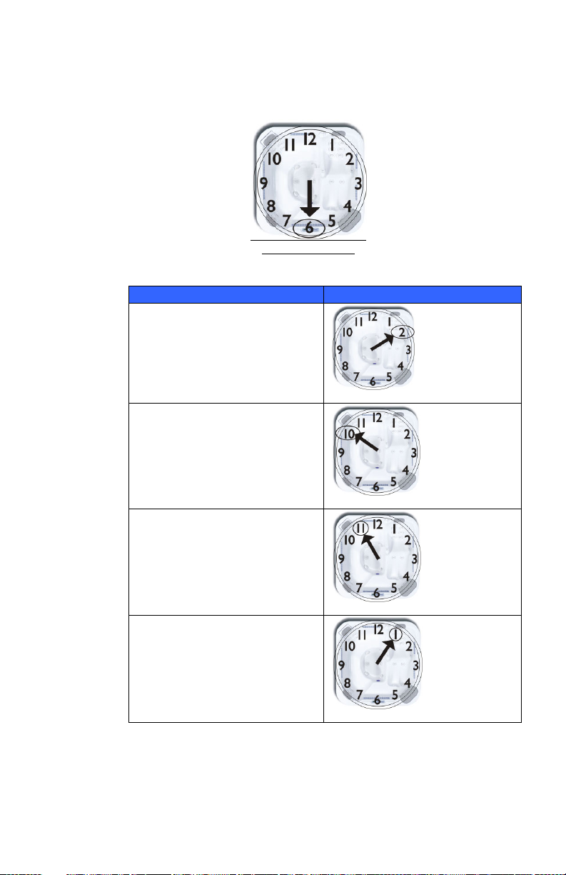
from one spa model to another. Use Table 4 to locate the
compartment on your spa. First, stand in front of the spa facing
the Top Side Control (at the 6 o’clock position, see below)
and then refer to Table 4 below.
10
Page 15
Export Sonic Immersion System Dealer Installation Guide
Sub-Woofer Installation Locator
Top Side Control
Table 4 Model List
Model and Number Location of Installation
Aurora II and Chairman
Top Side Control
Chairman II and Aurora XLT
Top Side Control
Diplomat, Californian
Top Side Control
Nautilus
Top Side Control
11
Page 16
Export Sonic Immersion System Dealer Installation Guide
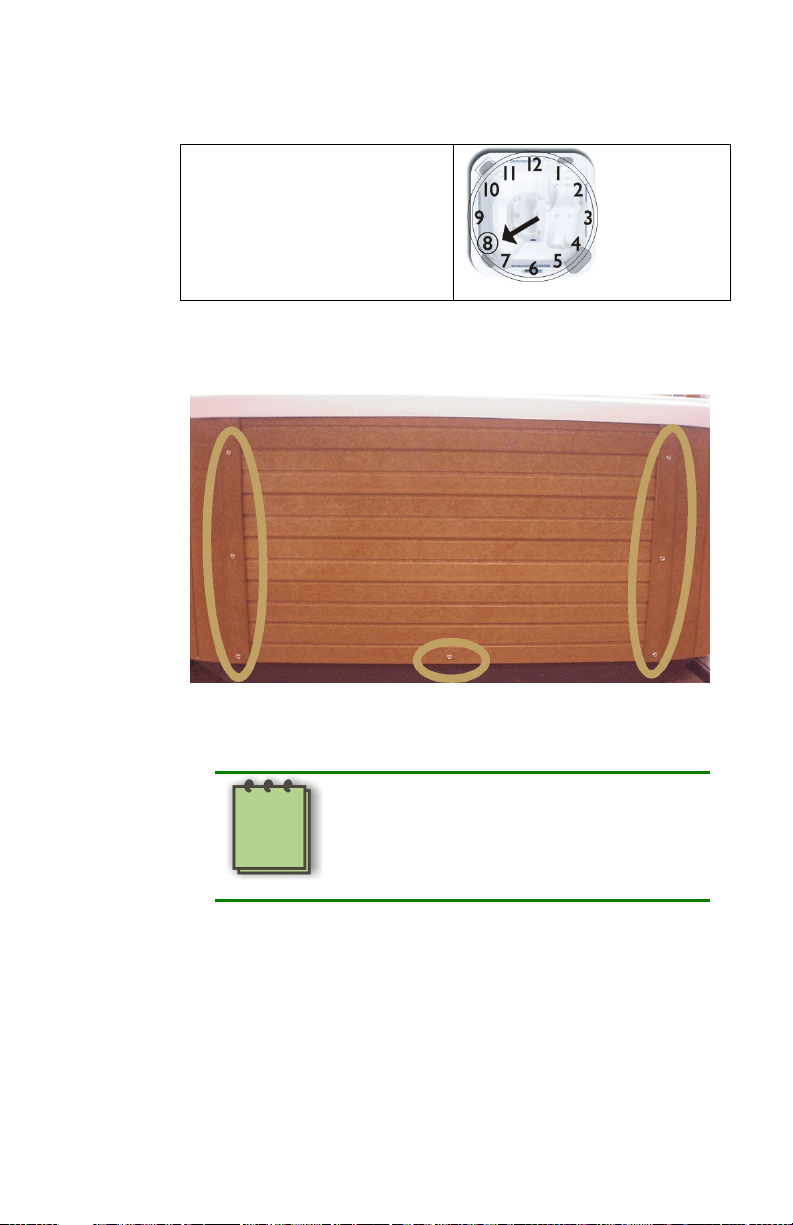
Caliente HP, Triad II, Aurora
HP, and Triad
Top Side Control
1. Use the screwdriver to remove the spa panel screws, Figure 3.
Figure 3. Equipment Compartment Panel Screws
The number of screws to be removed
will depend on the model of spa.
Note
12
Page 17
Export Sonic Immersion System Dealer Installation Guide
Installing the Sub Woofer Compartment
The installation of the sub woofer compartment consists of removing
the panel, removing the paper cover, exposing the plug, removing the
plug, and installing the sub woofer compartment.
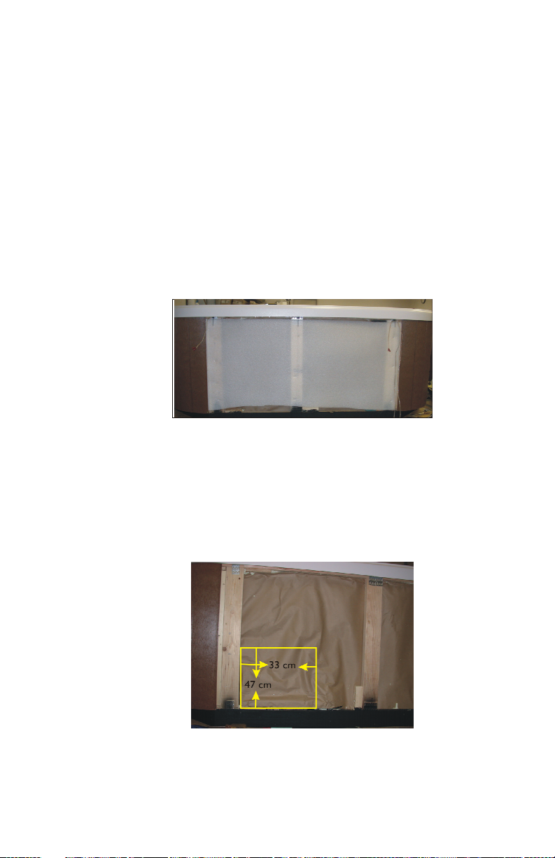
1. If you have a spa with wood siding you may skip to Step 2. If
your spa has EnviroTect siding you will need to remove the
white foam sheeting, Figure 4.
Figure 4. Removing EnviroTect Sheeting
2. Using a locking utility knife set for a depth of about ½ inch,
cut a 13” X 18.5” (33 cm X 47 cm) rectangle as shown in
Figure 5. Remove the paper and foam until you expose the
sub woofer plug. You may need to use a screwdriver or
other tool to remove the paper and foam.
Figure 5. Cutting Rectangle
13
Page 18

Export Sonic Immersion System Dealer Installation Guide
The photograph Figure 5 may not look
like your spa, refer to Table 4.
Note
1. Sub-Woofer Plug
Figure 6. Sub-Woofer Plug
3. Once the plug is exposed, Figure 6, use a screwdriver to
punch holes in the foam large enough to insert your hands
and pull the plug out of the spa, Figure 7.
The plug may not come out in one
piece.
Note
14
Page 19

Export Sonic Immersion System Dealer Installation Guide
Figure 7. Removing Plug
4. Use a medium size pair of needle nose pliers to remove the
large staples in the bottom rail where the plug was removed.
5. Remove all remnants of the plastic bag inside the
compartment where the plug was removed. This will expose
the electrical conduit, Figure 8.
The electrical conduit may not always
be in this location. It will vary from spa
to spa.
Note
15
Page 20

Export Sonic Immersion System Dealer Installation Guide
1. Electrical Conduit Before Trimming
Figure 8. Electrical Conduit
6. Using a non-ratcheting PVC pipe cutter, trim the electrical
conduit flush with the foam wall, Figure 9.
1. Electrical Conduit After Trimming
Figure 9. Conduit After Trimming
16
Page 21

Export Sonic Immersion System Dealer Installation Guide
7. Locate the sub woofer sub assembly (P/N 01564-09). Locate
the spot on the compartment that matches the location of
the conduit in the spa. Using a1½ inch (3.8 cm) hole saw, drill
a hole for the conduit, Figure 10.
Figure 10. Drilling Hole for Cables
8. Try to place the sub woofer compartment into the space
where the plug was removed. It must fit flush with the
bottom edge of the frame, Figure 11. In order to accomplish
this it may be necessary to remove additional foam.
17
Page 22

Export Sonic Immersion System Dealer Installation Guide
1. Bottom Edge of Frame
Figure 11. Edge of Frame
9. A properly positioned sub woofer compartment is shown in
Figure 12.
Figure 12. Properly Installed Sub-Woofer
18
Page 23

Export Sonic Immersion System Dealer Installation Guide
10. Once you are satisfied that the compartment fits properly,
secure the compartment to the frame, Figure 13, with 5 1“
(2.54 cm) coarse-threaded drywall screws (P/N 01051-06
provided in hardware package).
Figure 13. Attaching to Frame
Pre Wiring from Equipment Compartment to Sub Woofer Compartment
1. Feed the fish tape through the conduit from the sub-woofer
compartment to the equipment compartment, Figure 14.
19
Page 24

Export Sonic Immersion System Dealer Installation Guide
1. Fish Tape
Figure 14. Fish Tape in Equipment Compartment
2. Now locate the amplifier cables (two white and two red RCA
connectors on both ends, P/N 01570-24). Locate the threebranched harness assembly (P/N 01564-20). One branch will
be considerably longer than the other two.
3. Attach the preamp stereo cables (01570-24) and long branch
of main harness (01564-20) to fish tape using electrical tape,
Figure 15.
Figure 15. Attaching Cables and Harness to Fish Tape
20
Page 25

Export Sonic Immersion System Dealer Installation Guide
4. Apply a small amount of fish tape lubricant to a cloth and
then run the cables through the rag to give them a light
coating of lubricant, Figure 16.
Figure 16. Applying Lubricant to Cables
5. Now pull them through the conduit from the equipment
compartment to the sub-woofer compartment, Figure 17.
Figure 17. Cables in Sub-Woofer
6. Now that the harness and cables have been fished through
the conduit from the equipment compartment to the sub-
21
Page 26

Export Sonic Immersion System Dealer Installation Guide
woofer compartment, the wires and cables can be connected
to the amplifier in the sub-woofer compartment. You may
want to trim off some of the harness because it could be
longer than necessary. Make sure that when the wires are
connected to the amplifier that the amplifier can be moved
out to make adjustments. Using a wire stripper, strip
approximately ½ inch (1.27 cm) of insulator from the 3
conductor wires, Figure 18.
Figure 18. Stripping Wires
7. Connect the black wire to the terminal marked GND.
Connect the red wire to the terminal marked “+ BATT”, and
connect the blue wire to the terminal marked “REMOTE”,
Figure 19.
22
Page 27

Export Sonic Immersion System Dealer Installation Guide
1. Speaker Output Terminals. 2. Power Input Terminals 3. Red
Wire 4. Blue Wire 5. Black Wire
Figure 19. Connecting Wires for Power Input
8. Locate the wire coming from the sub-woofer. This wire is
covered with clear insulator. The wire has two conductors.
One is copper-colored and the other is silver. Strip
approximately ½ inch (1.27 cm) of insulator from each wire
and twist each to form a tight bundle. Connect the copper
colored wire to the terminal marked” CH2 (REAR) + LEFT”.
Connect the silver colored wire to the terminal marked”
CH2 (REAR) – RIGHT”, Figure 20.
1. Copper Wire 2. Silver Wire
Figure 20. Connecting Wires to Speaker Output
9. Connect red and white preamp input wires to the Line Level
Input terminals as follows: connect Channel 1 (flat speaker)
23
Page 28

Export Sonic Immersion System Dealer Installation Guide
to red and white terminals on left, connect Channel 2 (subwoofer speaker) to red and white terminals on right, Figures
21 and 22.
1. Line Level Input 2. Mode Control 3. Bass Boost Control 4.
HP/LP Crossover Control 5. Gain Controls 6. High Pass
Controls
Figure 21. Terminals and Controls
1. Channel 1 (used for Satellite Speakers) 2. Channel 2 (used for
Sub Woofer Speakers
Figure 22. Connecting Wires to Channel 1 and 2
10. Set GAIN CH 1 and CH 2 to 0.5V position, Figure 23.
11. Set MODE to the 3ch position.
24
Page 29

Export Sonic Immersion System Dealer Installation Guide
Figure 23. Setting Controls
12. Set BASS BOOST CH1 and CH 2 to the MIN position.
13. Set HIGH PASS CH 1 and CH 2 to the 200 HZ positions.
14. Set CH 1 to HP position and CH 2 to LP position.
Installation of Power Supply
Pre-Wire Power Supply
Locate the power supply kit that contains the power supply (P/N
01564-0) and a 12-pin connector (P/N 01564-19) containing wires in
the following configuration, see Figure 24.
25
Page 30

Export Sonic Immersion System Dealer Installation Guide
1. Green 2. Yellow 3. Red 4. Blue 5. Black 6. Row 3
Amplifier 7. Row 2 Stereo 8. Row 1 120 V Supply 9. Black
10. White
Figure 24. Connector Wire Configuration
1. Connect the wires from Row 1 (120 V Supply) to the power
supply as follows: black wire to the terminal marked ”AC-L”,
the white wire to terminal marked “AC-N”, and the green
wire to the terminal marked “FG”, Figure 25.
1. Black Wire 2. White Wire 3. Green Wire
Figure 25. Connecting Wires to 120 Volt Supply on
Power Supply
26
Page 31

Export Sonic Immersion System Dealer Installation Guide
2. Connect the wires coming from Row 2 (Stereo +12 V Supply)
as follows: (Figure 26) yellow and red wires to terminal
marked “DC+” and the black wire to terminal marked “DC“.
1. Black Wire 2. Red and Yellow Wires
Figure 26. Connecting Wires to Stereo and 12 V Supply
Terminals on Power Supply
3. Connect the wires coming from Row 3 (Amplifier) as follows
(see Figure 27): red wire to unused terminal marked “DC+”
and black wire to unused terminal marked “DC-“.
1. Black Wire 2. Red Wire
Figure 27. Connecting Wire to Amplifier Terminals on
Power Supply
27
Page 32

Export Sonic Immersion System Dealer Installation Guide
Installing Power Supply in Equipment Compartment
1. Turn the power supply so that you can see the Voltage
Selector Switch, see Figure 28, and place the switch in the
correct position (115V for UL and CSA spas or 240V for CE
spas) for your location.
1.Voltage Switch
Figure 28. Voltage Switch on Back of Power Supply
2. Locate two #8 x ½” (1.27 cm) Pan head screws (P/N 01011-
38) in the power supply kit. The power supply has two holes
for attaching it to the wall of the equipment compartment,
Figure 29. Locate the hole in the upper right corner of the
power supply. Use electric screwdriver to secure the power
supply. Now use the remaining screw to secure the left
bottom corner of the power supply.
28
Page 33

Export Sonic Immersion System Dealer Installation Guide
1. Location of Upper and Lower Screw Holes
Figure 29. Location of Attachment Holes on Power
Supply
3. Locate the connector on the harness assembly that matches
the one that you just installed on the power supply and
connect them together, Figure 30.
Figure 30. Connecting Harness to Power Supply
29
Page 34

Export Sonic Immersion System Dealer Installation Guide
Wiring the Power Supply
1. Locate the end of the harness that has a green, black, and
white wire (with connectors). Remove lower control box
cover. Insert these wires through the hole in the bottom of
the lower control box, Figure 31.
1. Wires Inserted through Hole in Bottom of Lower Control
Box
Figure 31. Inserting Wires in Lower Control Box
2. Using a 5/16” (7.9 mm) nut driver or wrench remove the
5/16” (7.9 mm) nut that secures the ground wires to the
bottom lower control box, see Figure 32.
30
Page 35

Export Sonic Immersion System Dealer Installation Guide
Figure 32. Removing Nut from Ground Terminal
3. Now place the green ground wire that you just inserted into
the lower control box over the screw, replace 5/16” (7.9
mm) nut, and secure with 5/16”(7.9 mm) nut driver or
wrench.
4. Connect the white and black wires to the pins as outlined in
Table 5.
Table 5 Pin Connectors
Board Description Pin Connections
MSPA-1-CE (240
V, 50Hz)
International
MSPA-MP-CE (240
V, 50 Hz)
International
Green – ground
White – P-98
Black – P-44
Green – ground
White – P-80
Black –P-39
31
Page 36

Export Sonic Immersion System Dealer Installation Guide
Determining Location of CD Weather Cover
The installation location of the CD Player Weather Cover (P/N
01564-04) depends on the model of the spa. The following steps will
guide you through the process of determining the installation location.
1. Refer to Figure 33. Measure distances A and B.
1. Detail of Stereo Recess Area 2. Corner Panel 3. Stereo
Recess 4. Distance B (Horizontal Position) 5. Distance A
(Vertical Position) 6. Top of Spa Base
Figure 33. Determining Location of CD Weather Cover
32
Page 37

Export Sonic Immersion System Dealer Installation Guide
It is important that the ruler or square
(see picture on previous page) be kept
level and at the top of the recess area
while making these measurements.
Note
2. Use the measurements determined in Step 1 and insert them
into the following formula:
Distance A = ______ Distance B = _______
A + 1” (2.54 cm) = Vertical Position (VP) _________
B + ¾” (1.91 cm) = Horizontal Position
(HP)________
3. Now proceed to Cutting Panel Hole for CD Player
Cutting Panel Hole for CD Player Door Assembly
1. Using number obtained for the Vertical Position (VP),
measure up from bottom of panel, see Figure 34, and mark
spot with a fine point marker.
33
Page 38

Export Sonic Immersion System Dealer Installation Guide
1. Bottom of Panel 2. Panel Lay Face Up 3. Top of Panel
Figure 34. Measuring Vertical Distance
2. Using measurement obtained for Horizontal Position (HP),
measure from side of panel, see Figure 35, and mark spot
with a fine point marker.
Figure 35. Measuring Horizontal Distance
34
Page 39

Export Sonic Immersion System Dealer Installation Guide
3. The point where these two lines intersect is the upper right
corner of the template (P/N Doc 74 Rev A).
4. Align the upper right corner of the template with the mark
on the panel. Use a center punch to mark the spot, Figure 36.
Figure 36. Aligning Template
5. Square up the template on the panel and use the center
punch to mark the other three corners.
6. Using a machinist’s square or straight edge, connect all four
marks, Figure 37.
Figure 37. Connecting Marks
35
Page 40

Export Sonic Immersion System Dealer Installation Guide
7. Using a 3/8” (9.5 mm) bit, drill holes in two corners of the
rectangle, Figure 38. Make certain that the holes are within
the lines. Using a center punch to mark the drilling centers
will prevent the drill bit from wandering.
1. Hole Locations
Figure 38. Hole Locations
8. Using a saber saw, cut out the rectangular piece from the
panel.
9. Depending on where the hole in the panel is located you may
need to use some Silicone caulking in the panel grooves to
prevent moisture from entering the CD player, see Figure 39.
1. Panel Cutout with Silicone Applied
Figure 39. Panel Cutout
36
Page 41

Export Sonic Immersion System Dealer Installation Guide
Installation of CD Player Door and Bezel
If the bezel is not removed from the door assembly (P/N 01564-04),
remove it by pulling from the bottom of the bezel and then proceed as
follows, see Figure 40:
1. Door Assembly 2. Bezel
Figure 40. Bezel and Door Assembly
2. Place the door assembly in the cutout. Make certain the door
will open and close freely. Door should open from bottom.
3. Locate 4 # 8 x 1” (2.54 cm) SS Truss Head screws (P/N
01011-40) provided with kit. Using an electric screwdriver
attach the door assembly to the panel, Figure 41.
To prevent wood panels from splitting,
driil pilot holes before installing the
door assembly.
Note
37
Page 42

Export Sonic Immersion System Dealer Installation Guide
Figure 41. Door Assembly Installed
4. Reattach the bezel.
5. Locate the mounting sleeve supplied with the CD player and
refer to the CD Player Owner’s manual for directions on
how to install this sleeve. Once the CD player mounting
sleeve is installed in the panel, proceed to the following
paragraph.
Installation of Panel and CD Player
1. Place the Dual Pole Antenna (P/N 01564-05) in the
equipment compartment.
2. Place the panel up against spa so that you can pull the main
harness, antenna, and amplifier cables through the door
assembly, Figure 42.
38
Page 43

Export Sonic Immersion System Dealer Installation Guide
Figure 42. Door Assembly Ready for CD Player
Connection
3. Reattach panel to spa.
4. Connect antenna, main harness and amplifier to CD player as
described in CD player owner’s manual. Connect power
supply cable (long branch of main harness) to power supply
connector on CD player. Connect Channel 1 preamp stereo
cables (RCA cable) to FRONT connectors on the CD player
and the Channel 2 cables to the REAR connectors on the CD
player.
Connecting the preamp cables (RCA
cables) in this manner will allow the
front and rear faders to increase or
decrease the sound level of the sub-
Note
woofer or satellite speakers.
5. Then slide CD player into sleeve and lock in position.
39
Page 44

Export Sonic Immersion System Dealer Installation Guide
Installing the Satellite Speakers
Locate the panel where you will install the speakers, Figure 43.
Figure 43. Typical Satellite Speaker Installation
1. Take the hinge mounting bracket connected to the speaker
(P/N 01564-14) and place it on the panel with the top
triangular portion of the hinge butting up against the lower
edge of the overhanging spa lip.
2. Remove the protective caps from the hinge screw holes and
using a center punch mark the locations for the screws.
3. Locate the four mounting screws that come with the hinges.
Using an electric screwdriver, attach the hinges to the spa
panel.
To prevent wood panels from splitting,
drill pilot holes before installing the
hinges.
Note
4. Replace the protective caps over the hinge screw, Figure 44.
40
Page 45

Export Sonic Immersion System Dealer Installation Guide
\
1. Caps in Place
Figure 44. Protective Caps in Place
41
Page 46

Export Sonic Immersion System Dealer Installation Guide
Installing the Satellite Speaker Wires
1. Remove the panel where you just finished installing the
speakers.
2. Locate two speaker wire sets (P/N 01564-21). The wires
have clear insulator with a silver and copper wire and female
connectors on one end.
3. Using a Cable Tyes and Cable Mounts (P/N 01200-006 and
01200-005), attach the wires to the frame in the approximate
location of the speakers directly below the edge of the spa,
see Figure 45, until you come to the corner panel.
1. Speaker Wires Attached with Cable Tyes and Mounts
Figure 45. Speaker Wires Attached
4. When you get to the corner panel use a thin, blunt object to
force the wires up under the overhanging lip of the spa and
the panel, Figure 46.
42
Page 47

Export Sonic Immersion System Dealer Installation Guide
1. When pushed all the way up under the lip, the wire or cable
will rest safely on the lip of the spa wall 2. Cable or Wire . 3.
Spa Shell’s Lip 4. Wooden Ruler or Paint Stir Stick 5. Install
Wire or Cable Under the Spa Shell’s Lip
Figure 46. Installing Speaker Wires
43
Page 48

Export Sonic Immersion System Dealer Installation Guide
5. Continue installing the wire until you reach the panel where
the sub-woofer compartment has been installed. Now use the
Cable Tyes and Cable Mounts to attach the wire to the wood
until you reach the sub woofer compartment, Figure 47.
1. Speaker Wires Coming from Satellite Speakers
Figure 47. Satellite Speaker Wires in Sub-Woofer
Compartment
6. Trim any excess wire leaving enough to connect the amplifier
and approximately 12 inches (30.5 cm) of slack. Then strip
approximately ½ “ (12.7 mm) of insulator from each wire.
7. Connect the wires to amplifier as shown in Figure 48.
44
Page 49

Export Sonic Immersion System Dealer Installation Guide
1. Copper Wire 2. Copper Wire 3. Silver Wire 4. Silver Wire
Figure 48. Connecting Satellite Speaker Wires to
Amplifier
8. Now connect the wires coming from the sub-woofer
compartment to the satellite speakers. The wires from the
speakers have male connectors and the wires coming from
the sub-woofer have female connectors, Figure 49.
Figure 49. Speaker Wires to Satellite Speakers
45
Page 50

Export Sonic Immersion System Dealer Installation Guide
9. Place the panel back on the spa and secure with screws. The
finished installation should appear as in the pictures shown in
Figure 50.
Figure 50. Completed Speaker Installation
46
Page 51

Export Sonic Immersion System Dealer Installation Guide
Securing the Amplifier
Now that the speakers have been installed and the amplifier has been
adjusted it can be secured to the frame, Figure 51, with dry wall
screws supplied in the kit (P/N 01051-06).
Figure 51. Securing Amplifier to the Frame
Complete the Installation
Replace the spa panels to complete the installation.
47
Page 52

Page 53

Page 54

Part No. 01510-1030E Rev A
2002 Dimension One Spas
 Loading...