


BST 768, SST 768, &
Dimension Elite
User Guide

2
Notice
The information in this document is subject to change without notice.
STRATASYS, INC. MAKES NO WARRANTY OF ANY KIND WITH REGARD TO THIS MATERIAL, INCLUDING, BUT NOT LIMITED TO, THE IMPLIED WARRANTIES OF MERCHANTABILITY AND FITNESS FOR A PARTICULAR PURPOSE. Stratasys, Inc. shall not be liable for errors contained herein or for incidental or consequential damages in connection with the furnishing, performance, or use of this material.
This equipment has been tested and found to comply with the limits for a Class A digital device, pursuant to part 15 of the FCC Rules. These limits are designed to provide reasonable protection against harmful interference when the equipment is operated in a commercial environment. This equipment generates, uses and can radiate radio frequency energy and, if not installed and used in accordance with the instruction manual, may cause harmful interference to radio communications. Operation of this equipment in a residential area is likely to cause harmful interference in which case the user will be required to correct the interference at his own expense.
Changes or modifications to the Dimension system not expressly approved by Stratasys, the party responsible for compliance, could void the user’s authority for use.
This document is protected by copyright. All rights reserved. Its use, disclosure, and possession are restricted by an agreement with Stratasys per software copyright. No part of this document may be photocopied, reproduced or translated into another language without the prior written consent of Stratasys, Inc. Printed in the USA.
Stratasys, Dimension, and Catalyst are registered trademarks of Stratasys, Inc. Krytox, Windows 2000, and Windows XP are registered trademarks of their respective companies.
© Copyright 2007 Stratasys, Incorporated.
March 2007
The Dimension system conforms with the following standards, in accordance with the EU Machinery, Low Voltage and Electromagnetic Compatibility Directives: EU 89/392/EEC, EU 98/37/EEC, EU 73/23/EEC amended by 93/68/EEC, EU 89/336/EEC
DimensionBST768,SST768,andEliteUserGuide

3
Introduction
Dimension is designed with ultimate simplicity in mind. The system enables you to build parts quickly, even if you have never used a 3D printer before. Its display panel prompts you to press a few keys to get you modeling quickly.
The system models with ABS plastic, so modeled parts are strong and durable. ABS also ensures that you will be able to drill, tap, sand, and paint your creations. With the speed and convenience of Breakaway Support Technology (BST 768) or Soluble Support Technology (SST 768 and Elite), completed parts are quickly available for review and test.
Dimension is an innovative combination of proprietary hardware, software, and material technology.
Congratulations…
you made a smart choice!
Dimension BST 768, SST 768, and Elite User Guide
4
How To Use This Manual
This User’s Guide is laid out in easy to follow sections which cover Set-up, Operation, Maintenance, and Troubleshooting of your Dimension printer. Be sure to read each section carefully so that you will get the best performance from your system.
Highlighted Information
The manual is written in a step-by-step format so as to guide you through a variety of operational tasks. Information of particular importance is presented in one of three formats
WARNING
A WARNING indicates a procedure that may cause Injury to an operator if the procedure is not followed. A WARNING will precede the paragraph of instruction to which it relates.
CAUTION
A CAUTION indicates a procedure that may cause Damage To Equipment if the procedure is not followed. A CAUTION will precede the paragraph of instruction to which it relates.
NOTE
A NOTE is used to highlight a specific point or to provide an operational tip. While useful, a NOTE does not indicate a procedure that can cause injury or damage if it is not followed. A NOTE will follow the paragraph of instruction to which it relates.
The Dimension printer guides you through operational tasks from a User Interface (UI) on the front panel of the printer. Throughout the User Guide, text representing messages that appear on the UI are presented in a specific format. Interface Messages appear as a bold, serif, fixed-pitch (mono-space) font.
DimensionBST768,SST768,andEliteUserGuide

5
Sections Of The Manual
Overview...
Provides a quick reference for the layout of the printer and its operating components. Overview also provides a quick reference for sources of additional information and printer supplies.
Setup...
Guides you through the initial printer installation and setup. Topics include unpacking, connecting power, installing software, and connecting to a computer network. Generally, topics in setup are only accomplished during installation or relocation of the printer.
Operation...
Further develops your understanding of the printer by presenting the User Interface, Loading and Unloading of Material, Building Parts, Removing Completed Parts, and Removing Support Material. The tasks presented are common procedures accomplished during the normal operation of the printer.
Maintenance...
Lists several tasks that you will need to perform to keep your printer performing at its best. Some tasks are ‘As Needed’ while others are determined by a set number of printer hours (CatalystEX includes an odometer of printer hours). ‘House Cleaning’, Axis Maintenance, Tip Cleaning Assembly Replacement, Chamber Lamp Replacement, and Tip Shroud Replacement are procedures that you can perform with the help of the User Guide.
Troubleshooting..
Allows you to perform some problem diagnosis and correction procedures in the event that your printer has a problem. A Troubleshooting Checklist, Fault Determination Codes, and a procedure to recover from a Loss of Extrusion are provided.
Dimension BST 768, SST 768, and Elite User Guide

6
DimensionBST768,SST768,andEliteUserGuide

|
Table of Contents 7 |
Table of Contents |
|
Introduction................................................................................ |
3 |
How To Use This Manual......................................................... |
4 |
Highlighted Information .................................................................. |
4 |
Sections Of The Manual................................................................. |
5 |
Overview................................................................................... |
11 |
Finding More Information ....................................................... |
14 |
Setting up Dimension ................................................................... |
14 |
Using Dimension .......................................................................... |
14 |
Supplies ................................................................................. |
15 |
Setup......................................................................................... |
17 |
Workspace ............................................................................. |
17 |
Unpacking .............................................................................. |
18 |
Installing Forklift Access Covers ............................................ |
20 |
Power Connections................................................................ |
20 |
Powering On Dimension ........................................................ |
22 |
Insert Modeling Base ............................................................. |
23 |
Installing Software.................................................................. |
24 |
Networking Your Printer......................................................... |
25 |
Connecting Directly To Your PC ............................................ |
28 |
Verifying Tip Depth................................................................. |
30 |
Operation.................................................................................. |
33 |
Display Panel and Keypad..................................................... |
33 |
Inserting a Modeling Base...................................................... |
34 |
Powering On Dimension ........................................................ |
34 |
Powering Off Dimension ........................................................ |
35 |
Cycling Power ........................................................................ |
35 |
Loading Material..................................................................... |
36 |
Dimension BST 768, SST 768, and Elite User Guide

8 Table of Contents |
|
Unloading Material ................................................................. |
39 |
Building a Test Part................................................................ |
41 |
Sending Your CAD File to the System ................................... |
41 |
Building a Part from Your File ...................................................... |
43 |
Chamber Lights...................................................................... |
43 |
Pausing Build ......................................................................... |
44 |
Resuming Build from Pause Mode......................................... |
44 |
Resuming Operations from Standby Mode ............................ |
44 |
Canceling a Job...................................................................... |
45 |
Removing a Completed Part .................................................. |
45 |
Removing Support Material.................................................... |
46 |
Breakaway Supports.................................................................... |
46 |
Soluble Supports.......................................................................... |
47 |
Maintenance ............................................................................. |
49 |
Startup Kit Tools..................................................................... |
49 |
After Each Build...................................................................... |
50 |
Empty Purge Container................................................................ |
50 |
500 Hour Maintenance........................................................... |
50 |
Clean Fan Filter............................................................................ |
50 |
Tip Cleaning Assembly (Brush/Flicker Assembly) ....................... |
51 |
2000 Hour Maintenance......................................................... |
52 |
Axis Maintenance......................................................................... |
52 |
As Needed Maintenance........................................................ |
53 |
Remove Debris Buildup ............................................................... |
53 |
Vacuum Build Chamber ............................................................... |
53 |
Clean Door Glass......................................................................... |
53 |
Chamber Lamp Replacement ...................................................... |
54 |
Tip Shroud Replacement - SST 768 and Elite Only..................... |
55 |
Dimension BST 768, SST 768, and Elite User Guide

|
Table of Contents 9 |
Troubleshooting ...................................................................... |
59 |
Troubleshooting Checklist...................................................... |
59 |
Fault Determination Codes .................................................... |
61 |
Loss of Extrusion.................................................................... |
61 |
Diagnosing Loss of Extrusion....................................................... |
61 |
Recovering From Loss of Extrusion ............................................. |
62 |
Dimension BST 768, SST 768, and Elite User Guide

10 Table of Contents
Dimension BST 768, SST 768, and Elite User Guide
Overview
Dimension builds models, including internal features, from CAD STL files. The system builds three-dimensional parts by extruding a bead of ABS plastic through a computer-controlled extrusion head, producing high quality parts that are ready to use immediately after completion. With two layer resolution settings, you can choose to build a part quickly for design verification, or you can choose a finer setting for higher quality surface detail.
The Dimension family consists of three 3D printers. Table 1 indicates the individual printer features.
Table 1: 3D Printer Features
Feature |
BST 768 |
SST 768 |
Elite |
|
|
|
|
|
|
|
|
|
|
|
.007 in. slice |
|
|
X |
|
(.178 mm) |
|
|
||
|
|
|
||
|
|
|
|
|
.010 in. slice |
X |
X |
X |
|
(.254 mm) |
||||
|
|
|
||
|
|
|
|
|
.013 in. slice |
X |
X |
|
|
(.330 mm) |
|
|||
|
|
|
||
|
|
|
|
|
P400 Model |
X |
X |
|
|
Material |
|
|||
|
|
|
||
|
|
|
|
|
P430 Model |
|
|
X |
|
Material |
|
|
||
|
|
|
||
|
|
|
|
|
BST |
|
|
|
|
(Breakaway |
X |
|
|
|
Support |
|
|
||
|
|
|
||
Material) |
|
|
|
|
|
|
|
|
|
SST |
|
|
|
|
(Soluble |
|
X |
X |
|
Support |
|
|||
|
|
|
||
Material) |
|
|
|
|
|
|
|
|
Dimension BST 768, SST 768, and Elite User Guide

12 Overview
|
|
7 |
1 |
|
8 |
|
||
|
|
|
2 |
|
9 |
|
|
10 |
3
4
 11
11
5
 12
12
6
|
Figure 1: Dimension Front View |
||
Item Nomenclature |
Item Nomenclature |
||
1 |
Extrusion Head |
7 |
Display Panel |
2 |
Extrusion Tips |
8 |
Tip Cleaning Assembly |
3 |
Guide Rods |
9 |
Purge Container |
4 |
Lead Screw |
10 |
Modeling Base |
5 |
Model Material Cartridge |
11 |
Z Platform |
6 |
Support Material Cartridge |
12 |
Platform Retainers (2) |
Dimension BST 768, SST 768, and Elite User Guide

Overview 13
|
|
3 |
|
|
2 |
|
|
|
1 |
|
4 |
|
|
|
5 |
|
|
|
6 |
|
Figure 2: Dimension Rear View |
||
Item Nomenclature |
Item Nomenclature |
||
1 |
Fan Cover |
4 |
UPS Connection |
2 |
Main Circuit Breaker |
5 |
Diagnostic Hookup |
3 |
Power Cord Adapter |
6 |
Network Cable |
|
|
|
Connection |
Dimension BST 768, SST 768, and Elite User Guide

14 Overview
The Dimension system consists of two primary components — the Dimension 3D printer and CatalystEX. CatalystEX is the preprocessing software that runs on a Windows 2000 or Windows XP Pro platform.
Dimension’s build envelope measures 203 x 203 x 305 mm (8 x 8 x 12 in). Each material cartridge contains 922 cc (56.3 cu. in.) of usable material — enough to build continuously for about four days without reloading.
Finding More Information
Several references are available for use with Dimension.
Setting up Dimension
Dimension User Guide
Step-by-step instructions for installing, setting up and operating the Dimension system.
Using Dimension
CatalystEX Online Help
Simple operating instructions for CatalystEX are available through the application. Help is displayed in the Dynamic Help window ...or... you can access them at from the Menu Bar - Help>Contents.
World Wide Web
Additional information is available at:
http://www.dimensionprinting.com
Dimension BST 768, SST 768, and Elite User Guide

Overview 15
Supplies
This section lists all replaceable supplies used by the Dimension modeling system. The parts mentioned in this list can be obtained by contacting the sales representative through whom you purchased your system.
Part Number |
|
Description |
|
|
|
Modeling Material - BST 768 and SST 768 Only |
||
|
|
|
340-20000 |
|
White ABS Filament Cartridge |
|
|
|
340-20200 |
|
Black ABS Filament Cartridge |
|
|
|
340-20300 |
|
Red ABS Filament Cartridge |
|
|
|
340-20400 |
|
Blue ABS Filament Cartridge |
|
|
|
340-20500 |
|
Green ABS Filament Cartridge |
|
|
|
340-20600 |
|
Yellow ABS Filament Cartridge |
|
|
|
340-20800 |
|
Steel Gray ABS Filament Cartridge |
|
|
|
Modeling Material - Elite Only |
|
|
|
|
|
340-21200 |
|
Natural P430 ABS Filament Cartridge |
|
|
|
Breakaway Support Material - BST 768 Only |
||
|
|
|
340-30000 |
|
Breakaway Support Cartridge |
|
|
|
Soluble Support Material/Concentrate - SST 768 and Elite Only |
||
|
|
|
340-30200 |
|
Soluble Support Cartridge |
|
|
|
300-00600 |
|
Soluble Soluble Concentrate (12 bottles) |
|
|
|
Modeling Base |
|
|
|
|
|
340-00200 |
|
Modeling Base (qty. 24) |
|
|
|
To order supplies for your Dimension system, contact your local Dimension reseller.
Dimension BST 768, SST 768, and Elite User Guide

16 Overview
Dimension BST 768, SST 768, and Elite User Guide

Setup
Workspace
Observe the following when placing Dimension in its operating location:
•Dimension has an approximate weight of 128 kg (282 lbs.) and requires a table capable of safely supporting 136 kg (300 lbs).
•System Dimensions:
914 x 686 x 1041 mm (36 x 27 x 41 in)
Four-inch minimum space behind unit for air circulation
•Dedicated outlet requirements (Nominal):
100-120 VAC, 60 Hz, 15 A min. (20 amp recommended) –or–
220-240 VAC, 50/60 Hz, 7 A min. (10 amp recommended)
•Temperature: 18–32 C (65-90 F)
•Relative Humidity: 30-80%, Non-condensing
•Ethernet 10/100 Base T network
•Network patch cable with RJ45 connectors
•Optional UPS for power interruptions (brown-out conditions):
Rated Power – 2200 VA Output Power – 1600 watts
Dimension BST 768, SST 768, and Elite User Guide

18 Setup
Unpacking
This section describes the recommended procedures for unpacking and preparing Dimension for its first use.
Unpack the printer:
WARNING
The Dimension printer weighs approximately 128 kg (282 lbs). Use proper moving and lifting techniques when positioning the unit. For your convenience, there are forklift pads built into the bottom of the unit. They are accessible from the side of the unit.
1.Before unpacking the printer, move it near to its operating location.
2.Remove the plastic banding from around the cardboard.
3.Remove the top cover. Set aside the fork access covers (2) and bag of screws (2).
4.Remove screws (4) that attach cardboard to pallet and remove the cardboard side panels.
5.Remove the top foam.
6.Remove outer plastic wrap - use care if using a knife so as to not scratch the printer.
7.Remove the foam door channels (2) and tape.
WARNING
The Lead Screw and Guide Rods are lubricated with a thin coat of Krytox grease. Krytox grease can cause skin irritation. Be careful not to get the grease on your hands or clothing.
Dimension BST 768, SST 768, and Elite User Guide
Setup 19
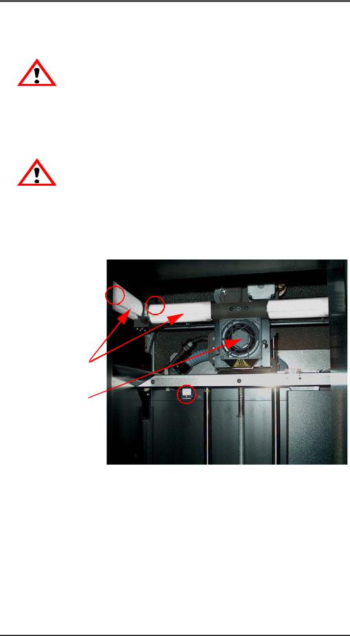
CAUTION
Remove the foam tubes that isolate the extrusion head from the frame (see Figure 3). The printer will be damaged if powered on with the foam tubes in place.
CAUTION
Be careful not to damage the rod sensors when removing the foam tubes (see
Figure 3).
8.Remove the foam tubes that isolate the extrusion head from the frame (see Figure 3).
Circles indicate Rod Sensor locations. There are also two sensors on the back side of the Extrusion Head.
Foam Tubes (4)
Extrusion Head
(SST 768 & Elite
Shown)
Figure 3: Foam tubes isolating the extrusion head from the Z-axis frame
9.After unpacking, inspect the printer and report any shipping damage to the carrier.
Dimension BST 768, SST 768, and Elite User Guide
20 Setup
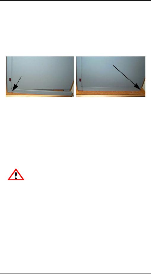
Installing Forklift Access Covers
The forklift access covers can be placed over the forklift channels after the printer is placed in its final location (see Figure 4). The covers are press-fit in the front and held in place with one screw in the rear.
Attachment Screw
on Back of Printer
Insert Tab in Slot
Push Cover Toward Front of Printer
Figure 4: Installing the forklift access covers
Power Connections
This section discusses the procedure for preparing all power connections for the printer.
CAUTION
Before connecting power to the printer, make sure that the Dimension circuit breaker is in the off (down) position. It is located in the rear of the printer next to the power cord attachment point.
Dimension is provided with two power cords: one for 110 V and one for 220 V.
Prepare all power connections:
1.Connect the male end of the supplied power cord directly into a grounded electrical outlet, as shown in Figure 5 on page 21. (If using a Uninterrupted Power Supply (UPS), connect the cord directly into the UPS).
Dimension BST 768, SST 768, and Elite User Guide
Setup 21
Figure 5: Connecting to a grounded electrical outlet
CAUTION
Do not use an extension cord or power strip with the Dimension system. Connect the cord directly into the receptacle or UPS.
2.Connect the female end of the power cord directly into the rear of the cabinet.
3.Switch the Dimension circuit breaker to the on (up) position. Power is now supplied to the Dimension system. The system is ready to be ‘Powered ON’.
Dimension BST 768, SST 768, and Elite User Guide
 Loading...