

Dimatix
Materials
Printer
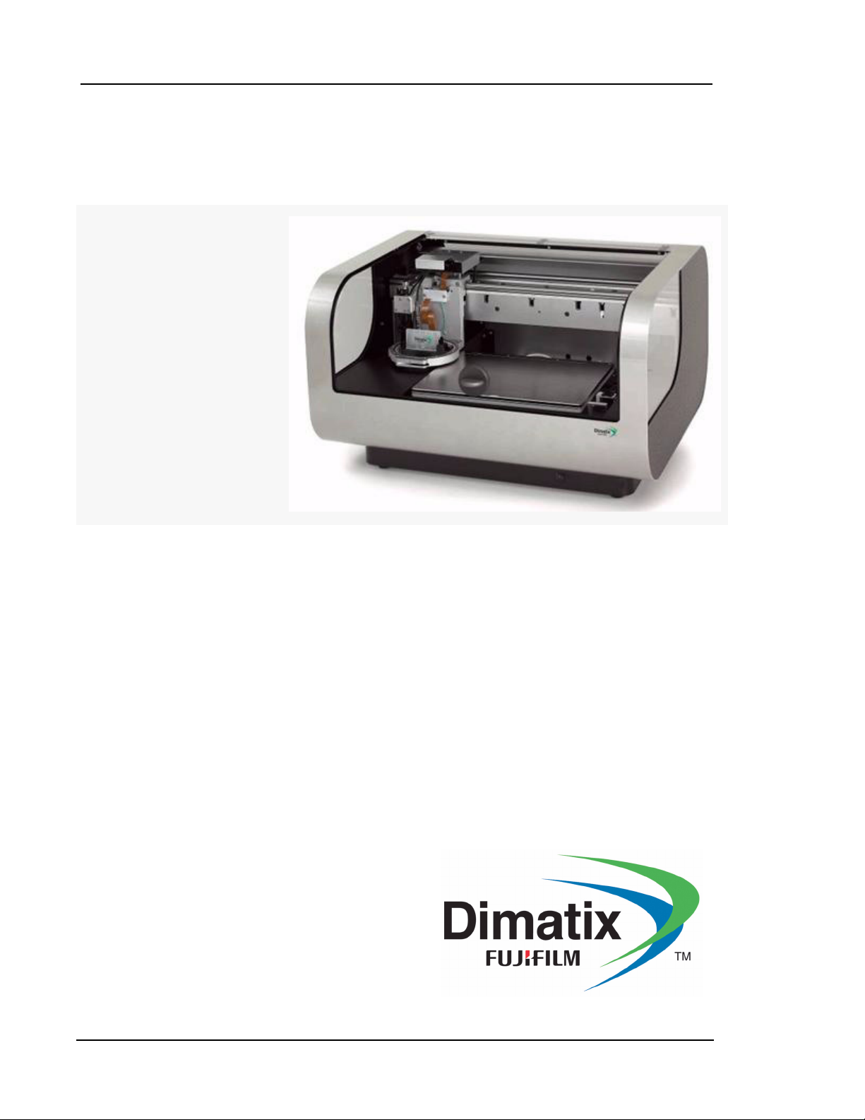
Dimatix Materials Printer
DMP-2800 Series
User Manual
ii Dimatix Materials Printer
!
WARNING
CAUTION
!
1.0 About this Manual
Throughout this manual a variety of conventions are used to highlight essential
information that is important for the overall safety and understanding of issues in using
this product. These include:
1.1 Warnings
This symbol identifies information about
procedures, practices or conditions that can result
in damage to the product, economic loss, personal
injury, or death.
(Dieses Symbol kennzeichnet Hinweise zu
Handlungsweisen, Methoden oder Zuständen die
zu Schäden am Produkt, wirtschftlichem Verlußt,
Personenschäden oder zum Tode führen können.)
1.2 Cautions
This symbol identifies information about practices
or circumstances that may lead to damage to the
product or other economic loss.
(Dieses Symbol kennzeichnet Hinweise zu
Handlungsweisen oder Umstände die zu Schäden
am Produkt oder anderen wirtschaftlichen Schäden
führen können.)
1.3 ESD Advisory ESD = Electrostatic Sensitive Device (
gefährdetes Bauteil)
This symbol identifies where there may be risk of
damage to the product due to Electrostatic
Discharge.
(Dieses Symbol kennzeichnet Punkte an denen das
Produkt durch elektrostatische Entladung
beschädigt werden könnte.)
EGB = elektrostatisch
Doc. # PM000040 Rev. 01 FUJIFILM Dimatix, Inc. Confidential Information
March 26, 2008

Dimatix Materials Printer iii
IMPORTANT
IMPORTANT
1.4 Wheelie Bin Symbol
This symbol identifies parts that should be
reclaimed as part of the Waste Electrical and
Electronic Equipment (WEEE) Directive.
1.5 Important
This symbol identifies information that is essential
to the understanding and correct use of this product.
(Dieses Symbol kennzeichnet, für das Verständnis
und den richtigen Umgang mit dem Gerät,
wesentliche Hinweise.)
1.6 Notes
Note: Used for emphasizing additional information that aids in the understanding
and use of the product.
2.0 Important Safety Information (Wichtige Sicherheitshinweise)
2.1 Safety
(Sicherheit)
FUJIFILM Dimatix, Inc. Confidential Information Doc. # PM000040 Rev. 01
March 26, 2008
iv Dimatix Materials Printer
!
WARNING
!
WARNING
!
WARNING
Only qualified, service-trained personnel who are aware
of the hazards involved should perform calibration,
maintenance, or repair of the product. Only these
qualified personnel should remove the covers from the
product.
(Kalibrierungen, Wartungen oder Reparaturen am
Produkt sollten nur von qualifiziertem Servicepersonal,
das sich den bestehenden Gefahren bewusst ist,
vorgenommen werden. Nur qualifiziertes Servicepersonal
sollte die Abdeckungen am Produkt entfernen.)
For continued protection against fire, replace the line
fuses only with fuses of the specified type and rating.
(Ersetzen Sie die Eingangssicherung nur mit Sicherungen
des spezifizierten Typs und der spezifizierten Leistung,
um einen sicheren Betrieb zu gewährleisten und Bränden
vorzubeugen.)
Modification or misuse of the product or components can
cause harm to the user and will void any warranty.
(Veränderungen oder Missbrauch des Produkts, oder
Veränderungen oder Missbrauch von Komponenten
können den Benutzer oder Dritte schädigen und führen
zum Garantieverlußt.)
Doc. # PM000040 Rev. 01 FUJIFILM Dimatix, Inc. Confidential Information
March 26, 2008
Dimatix Materials Printer v
!
WARNING
!
WARNING
!
WARNING
The product must be connected to a protective earth
conductor via the three-wire power cable. The power plug
shall be inserted only into a grounded outlet. Do not
defeat the protective action by using an extension cord
without a grounded conductor.
(Das Produkt muß durch den Betrieb mit einem
dreiadrigen Stromkabel geerdet werden. Der Stecker darf
nur in eine geerdete Steckdose gesteckt werden.
Benutzten sie nur dreiadrige Verlängerungskabel mit
Erdung.)
For Dimatix Materials Printer (DMP-2800) serial
numbers less than 2831-0646-XXXX-XXXXXXXXX:
Fluid used in this product must have a fire point greater
than 125 °C.
(Beachten sie bei Dimatix Material Druckern (DMP-
2800) mit einer Seriennummer kleiner als 2831-0646XXXX-XXXXXXXXX: Fluide die in diesem Produkt
benutzt werden müssen einen Flammpunkt grösser als
125 °C aufweisen.)
Do not overfill the ink cartridge. Its maximum capacity is
1.5 milliliters.
(Überfüllen sie die Druckerpatrone nicht. Das maximale
Fassungsvermögen der Druckerpatrone beträgt 1,5
Milliliter.)
FUJIFILM Dimatix, Inc. Confidential Information Doc. # PM000040 Rev. 01
March 26, 2008

vi Dimatix Materials Printer
!
WARNING
!
WARNING
!
WARNING
Do not operate the product in an explosive atmosphere.
Do not operate the product in the presence of
inflammable gases or fumes. Operation of any electrical
instrument in such an environment clearly constitutes a
safety hazard.
(Benutzten sie das Gerät nicht in explosiver Atmosphäre.
Benutzen sie das Gerät nicht in der Nähe von
entflammbaren Gasen oder Dämpfen. Der Einsatz
jeglicher elektronischer Geräte in einer solchen
Umgebung stellt eine eindeutige Sicherheitsgefährdung
dar.)
Care must be used when jetting multiple fluids. It may be
possible for reactions to occur in the absorbent pads
where multiple and or incompatible fluids may come in
contact with each other.
(Vorsicht ist beim Umgang und Druck mehrerer
verschiedener Flüssigkeiten geboten. Es ist möglich, dass
Reaktionen in den Absorberkissen stattfinden, wenn
inkompatible Flüssigkeiten miteinander in Kontakt
geraten können.)
The platen can reach temperatures of 60 °C which is hot
to the touch. It can melt some materials if placed on it
while hot, and it can cause volatile materials to evaporate
faster if placed on the platen when hot.
(Die Substratplatte kann Temperaturen von bis zu 60 °C
erreichen. Dies ist zu heiss, um sie gefahrlos zu berühren.
Diese Temperatur kann Materialien zum schmelzen
bringen, wenn diese auf die Platte gestellt werden.
Ausserdem verdampfen flüchtige Materialien schneller
wenn sie auf die heisse Platte gestellt werden.)
Doc. # PM000040 Rev. 01 FUJIFILM Dimatix, Inc. Confidential Information
March 26, 2008

Dimatix Materials Printer vii
!
WARNING
IMPORTANT
IMPORTANT
IMPORTANT
IMPORTANT
The cartridge can reach temperatures of 70 °C which is
hot to the touch, and it can cause volatile materials to boil
off faster. Care must be taken that the cartridge settings
are appropriate when installing a cartridge with volatile
fluids.
(Das Cartridge kann Temperaturen von bis zu 70 °C
erreichen. Dies ist zu heiss, um es zu berühren.
Ausserdem verdampfen flüchtige Materialien schneller
wenn sie das heisse Cartridge berühren. Die Cartridge
Einstellungen müssen sehr sorgfältig gewählt werden,
wenn mit leicht flüchtigen Materialien im Cartridge
gearbeitet wird.)
2.2 Important (Wichtig)
All moving parts are interlocked to the printer lid. The
machine will stop if the lid is lifted during operation.
(Alle beweglichen Teile sind mit der Drucker-Klappe
gekoppelt. Die Maschine bleibt stehen wenn die Klappe
im Betrieb geöffnet wird.)
Replaceable pads capture and hold virtually all ink jetted
into them. In many cases this may then be considered
“solid waste” rather than “liquid waste.” Please dispose of
properly.
(Die austauschbaren Absorberkissen können fast alle
Tinten aufnehmen. In vielen Fällen gilt dies ehr als
„Fester Abfall“ und nicht als „Flüssiger Abfall“, bitte
entsorgen sie diesen fachgerecht.)
FUJIFILM Dimatix, Inc. Confidential Information Doc. # PM000040 Rev. 01
March 26, 2008

viii Dimatix Materials Printer
IMPORTANT
IMPORTANT
IMPORTANT
IMPORTANT
This product complies with INSTALLATION
CATEGORY II and POLLUTION DEGREE 2 in
IEC61010-1. This product is an INDOOR USE product.
(Dieses Produkt erfüllt die Forderungen der „Installation
Category II“ und „Pollution Degree 2“ nach IEC61010-1.
Dieses Produkt ist ein Produkt für den Gebrauch in
trockenen Räumen.)
The LEDs within this product are Class 1 in accordance
with IEC60825-1, CLASS 1 LED PRODUCT.
(Die LEDs in diesem Produkt entsprechen Class 1 nach
IEC60825-1, Class 1 LED Product.)
Do not dispose this product as unsorted municipal
waste. Collection of such waste separately for
special treatment is necessary.
(Entsorgen sie dieses Produkt nicht als
unsortierten Hausmüll. Eine fachgerechte
Entsorgung ist nötig.)
Note: This equipment has been tested and complies with the limits for a Class
A digital device, pursuant to part 15 of the FCC Rules. These limits are
designed to provide reasonable protection against harmful interference
when the equipment is operated in a commercial environment. This
equipment generates, uses, and can radiate radio frequency energy and,
if not installed and used in accordance with the instruction manual, may
cause harmful interference to radio communications. Operation of this
equipment in a residential area is likely to cause harmful interference in
which case the user will be required to correct the interference at one’s
own expense.
Note: This product complies with the radio interference requirements of the
European Union.
Doc. # PM000040 Rev. 01 FUJIFILM Dimatix, Inc. Confidential Information
March 26, 2008

Table of Contents
Dimatix Materials Printer
About this Manual . . . . . . . . . . . . . . . . . . . . . . . . . . . . . . . . . . . . . . . . . . . . . . . . . . . . . . . . . . ii
Warnings . . . . . . . . . . . . . . . . . . . . . . . . . . . . . . . . . . . . . . . . . . . . . . . . . . . . . . . . . . . . . . ii
Cautions . . . . . . . . . . . . . . . . . . . . . . . . . . . . . . . . . . . . . . . . . . . . . . . . . . . . . . . . . . . . . . . ii
ESD Advisory ESD = Electrostatic Sensitive Device (EGB = elektrostatisch gefährdetes
Bauteil). . . . . . . . . . . . . . . . . . . . . . . . . . . . . . . . . . . . . . . . . . . . . . . . . . . . . . . . . . . . . . . . ii
Wheelie Bin Symbol . . . . . . . . . . . . . . . . . . . . . . . . . . . . . . . . . . . . . . . . . . . . . . . . . . . . iii
Important . . . . . . . . . . . . . . . . . . . . . . . . . . . . . . . . . . . . . . . . . . . . . . . . . . . . . . . . . . . . . iii
Notes . . . . . . . . . . . . . . . . . . . . . . . . . . . . . . . . . . . . . . . . . . . . . . . . . . . . . . . . . . . . . . . . iii
Important Safety Information (Wichtige Sicherheitshinweise) . . . . . . . . . . . . . . . . . . . . . . . iii
Safety (Sicherheit) . . . . . . . . . . . . . . . . . . . . . . . . . . . . . . . . . . . . . . . . . . . . . . . . . . . . . . iii
Important (Wichtig) . . . . . . . . . . . . . . . . . . . . . . . . . . . . . . . . . . . . . . . . . . . . . . . . . . . . . vii
Chapter 1 Introduction
System Accessories . . . . . . . . . . . . . . . . . . . . . . . . . . . . . . . . . . . . . . . . . . . . . . . . . . . . . . . . . 2
System Requirements. . . . . . . . . . . . . . . . . . . . . . . . . . . . . . . . . . . . . . . . . . . . . . . . . . . . . . . . 2
System Identification . . . . . . . . . . . . . . . . . . . . . . . . . . . . . . . . . . . . . . . . . . . . . . . . . . . . . . . . 2
Chapter 2 Set-Up and Installation
Unpacking . . . . . . . . . . . . . . . . . . . . . . . . . . . . . . . . . . . . . . . . . . . . . . . . . . . . . . . . . . . . . . . . 5
DMP . . . . . . . . . . . . . . . . . . . . . . . . . . . . . . . . . . . . . . . . . . . . . . . . . . . . . . . . . . . . . . . . . . 5
PC. . . . . . . . . . . . . . . . . . . . . . . . . . . . . . . . . . . . . . . . . . . . . . . . . . . . . . . . . . . . . . . . . . . . 7
PC Start up . . . . . . . . . . . . . . . . . . . . . . . . . . . . . . . . . . . . . . . . . . . . . . . . . . . . . . . . . . . . . . . . 8
Starting Your DMP . . . . . . . . . . . . . . . . . . . . . . . . . . . . . . . . . . . . . . . . . . . . . . . . . . . . . . . . . 9
Dimatix Drop Manager . . . . . . . . . . . . . . . . . . . . . . . . . . . . . . . . . . . . . . . . . . . . . . . . . . . . . 10
Chapter 3 Initial Start-Up Operation
Install Cartridge . . . . . . . . . . . . . . . . . . . . . . . . . . . . . . . . . . . . . . . . . . . . . . . . . . . . . . . . . . . 11
Select Pattern . . . . . . . . . . . . . . . . . . . . . . . . . . . . . . . . . . . . . . . . . . . . . . . . . . . . . . . . . . . . . 14
Load/Unload Substrate . . . . . . . . . . . . . . . . . . . . . . . . . . . . . . . . . . . . . . . . . . . . . . . . . . . . . 15
Print Set-Up . . . . . . . . . . . . . . . . . . . . . . . . . . . . . . . . . . . . . . . . . . . . . . . . . . . . . . . . . . . . . . 16
Nozzle Test Pattern . . . . . . . . . . . . . . . . . . . . . . . . . . . . . . . . . . . . . . . . . . . . . . . . . . . . . 17
Advanced Uses. . . . . . . . . . . . . . . . . . . . . . . . . . . . . . . . . . . . . . . . . . . . . . . . . . . . . . . . . . . . 18
FUJIFILM Dimatix, Inc. Confidential Information Doc. # PM000040 Rev. 01
March 26, 2008

x Table of Contents
Chapter 4 Screen Descriptions
Main Screen. . . . . . . . . . . . . . . . . . . . . . . . . . . . . . . . . . . . . . . . . . . . . . . . . . . . . . . . . . . . . . 19
File Menu . . . . . . . . . . . . . . . . . . . . . . . . . . . . . . . . . . . . . . . . . . . . . . . . . . . . . . . . . . . . 20
Tools Menu . . . . . . . . . . . . . . . . . . . . . . . . . . . . . . . . . . . . . . . . . . . . . . . . . . . . . . . . . . . 20
Help menu . . . . . . . . . . . . . . . . . . . . . . . . . . . . . . . . . . . . . . . . . . . . . . . . . . . . . . . . . . . 20
Cartridge Settings . . . . . . . . . . . . . . . . . . . . . . . . . . . . . . . . . . . . . . . . . . . . . . . . . . . . . . . . . 22
Waveform Tab. . . . . . . . . . . . . . . . . . . . . . . . . . . . . . . . . . . . . . . . . . . . . . . . . . . . . . . . . 22
Cartridge Tab. . . . . . . . . . . . . . . . . . . . . . . . . . . . . . . . . . . . . . . . . . . . . . . . . . . . . . . . . . 24
Cleaning Cycles Tab . . . . . . . . . . . . . . . . . . . . . . . . . . . . . . . . . . . . . . . . . . . . . . . . . . . . 25
Cleaning Cycle Editor . . . . . . . . . . . . . . . . . . . . . . . . . . . . . . . . . . . . . . . . . . . . . . . . . . . . . . 26
Waveform Editor. . . . . . . . . . . . . . . . . . . . . . . . . . . . . . . . . . . . . . . . . . . . . . . . . . . . . . . . . . 29
Individual Segment Controls. . . . . . . . . . . . . . . . . . . . . . . . . . . . . . . . . . . . . . . . . . . . . . 30
Overall Waveform Controls . . . . . . . . . . . . . . . . . . . . . . . . . . . . . . . . . . . . . . . . . . . . . . 30
Non-Jetting Waveform . . . . . . . . . . . . . . . . . . . . . . . . . . . . . . . . . . . . . . . . . . . . . . . . . . 31
Jetting Waveform vs. Non-Jetting Waveform. . . . . . . . . . . . . . . . . . . . . . . . . . . . . . . . . 31
Replacing Cleaning Pad . . . . . . . . . . . . . . . . . . . . . . . . . . . . . . . . . . . . . . . . . . . . . . . . . . . . 31
Chapter 5 Pattern Printing
Select Pattern. . . . . . . . . . . . . . . . . . . . . . . . . . . . . . . . . . . . . . . . . . . . . . . . . . . . . . . . . . . . . 35
Pre-Defined Standard Patterns . . . . . . . . . . . . . . . . . . . . . . . . . . . . . . . . . . . . . . . . . . . . 36
Create Your Own Pattern . . . . . . . . . . . . . . . . . . . . . . . . . . . . . . . . . . . . . . . . . . . . . . . . . . . 36
Substrate . . . . . . . . . . . . . . . . . . . . . . . . . . . . . . . . . . . . . . . . . . . . . . . . . . . . . . . . . . . . . 37
Pattern Block Array. . . . . . . . . . . . . . . . . . . . . . . . . . . . . . . . . . . . . . . . . . . . . . . . . . . . . 39
Pattern Block Drop Position . . . . . . . . . . . . . . . . . . . . . . . . . . . . . . . . . . . . . . . . . . . . . . 40
Draw feature . . . . . . . . . . . . . . . . . . . . . . . . . . . . . . . . . . . . . . . . . . . . . . . . . . . . . . . . 40
Drop Spacing. . . . . . . . . . . . . . . . . . . . . . . . . . . . . . . . . . . . . . . . . . . . . . . . . . . . . . . . . . 43
Bitmap and Gerber File Printing . . . . . . . . . . . . . . . . . . . . . . . . . . . . . . . . . . . . . . . . . . . . . . 44
Gerber Files. . . . . . . . . . . . . . . . . . . . . . . . . . . . . . . . . . . . . . . . . . . . . . . . . . . . . . . . . . . 44
Substrate Tab . . . . . . . . . . . . . . . . . . . . . . . . . . . . . . . . . . . . . . . . . . . . . . . . . . . . . . . 45
Placement . . . . . . . . . . . . . . . . . . . . . . . . . . . . . . . . . . . . . . . . . . . . . . . . . . . . . . . . . . 46
Tiling . . . . . . . . . . . . . . . . . . . . . . . . . . . . . . . . . . . . . . . . . . . . . . . . . . . . . . . . . . . . . 47
Reference Point . . . . . . . . . . . . . . . . . . . . . . . . . . . . . . . . . . . . . . . . . . . . . . . . . . . . . 47
Print Preview. . . . . . . . . . . . . . . . . . . . . . . . . . . . . . . . . . . . . . . . . . . . . . . . . . . . . . . . . . . . . 49
Cartridge Mounting Angle . . . . . . . . . . . . . . . . . . . . . . . . . . . . . . . . . . . . . . . . . . . . . . . . . . 53
Chapter 6 Drop Watcher
Drop Watcher . . . . . . . . . . . . . . . . . . . . . . . . . . . . . . . . . . . . . . . . . . . . . . . . . . . . . . . . . . . . 57
Drop Watcher Pad . . . . . . . . . . . . . . . . . . . . . . . . . . . . . . . . . . . . . . . . . . . . . . . . . . . . . . 58
Tools Tab. . . . . . . . . . . . . . . . . . . . . . . . . . . . . . . . . . . . . . . . . . . . . . . . . . . . . . . . . . . . . 62
Fiducial Camera . . . . . . . . . . . . . . . . . . . . . . . . . . . . . . . . . . . . . . . . . . . . . . . . . . . . . . . . . . 68
Doc. # PM000040 Rev. 01 FUJIFILM Dimatix, Inc. Confidential Information
March 26, 2008

Table of Contents xi
Features. . . . . . . . . . . . . . . . . . . . . . . . . . . . . . . . . . . . . . . . . . . . . . . . . . . . . . . . . . . . . . . 70
Alignment Procedures. . . . . . . . . . . . . . . . . . . . . . . . . . . . . . . . . . . . . . . . . . . . . . . . . . . . . . . 72
Tools Menu in the Fiducial Camera Window . . . . . . . . . . . . . . . . . . . . . . . . . . . . . . . . . 72
Options menu in the Fiducial Camera Window. . . . . . . . . . . . . . . . . . . . . . . . . . . . . . 87
Chapter 7 Fluid Requirements
Dimatix Model Fluid MFL-002 . . . . . . . . . . . . . . . . . . . . . . . . . . . . . . . . . . . . . . . . . . . . . . . 89
Drop Formation. . . . . . . . . . . . . . . . . . . . . . . . . . . . . . . . . . . . . . . . . . . . . . . . . . . . . . . . . . . . 90
Performance . . . . . . . . . . . . . . . . . . . . . . . . . . . . . . . . . . . . . . . . . . . . . . . . . . . . . . . . . . . . . . 91
Drop Velocity vs. Frequency . . . . . . . . . . . . . . . . . . . . . . . . . . . . . . . . . . . . . . . . . . . . . . 92
Drop Velocity vs. Voltage with different Viscosities. . . . . . . . . . . . . . . . . . . . . . . . . . . . 92
Voltage vs. Drop Mass . . . . . . . . . . . . . . . . . . . . . . . . . . . . . . . . . . . . . . . . . . . . . . . . . . . 93
Chapter 8 Waveform Basics
Waveform editor window explanation . . . . . . . . . . . . . . . . . . . . . . . . . . . . . . . . . . . . . . . . . . 96
Chapter 9 Cartridge
Fluid Module Filling. . . . . . . . . . . . . . . . . . . . . . . . . . . . . . . . . . . . . . . . . . . . . . . . . . . . . . . 102
Fill Syringe . . . . . . . . . . . . . . . . . . . . . . . . . . . . . . . . . . . . . . . . . . . . . . . . . . . . . . . . . . 102
Assembly . . . . . . . . . . . . . . . . . . . . . . . . . . . . . . . . . . . . . . . . . . . . . . . . . . . . . . . . . . . . . . . 104
Attach Fluid Module to Jetting Module . . . . . . . . . . . . . . . . . . . . . . . . . . . . . . . . . . . . . 104
Cartridge Maintenance . . . . . . . . . . . . . . . . . . . . . . . . . . . . . . . . . . . . . . . . . . . . . . . . . . . . . 105
Cleaning Function Definitions . . . . . . . . . . . . . . . . . . . . . . . . . . . . . . . . . . . . . . . . . . . . 106
Failure Modes, Prevention and Recovery. . . . . . . . . . . . . . . . . . . . . . . . . . . . . . . . . . . . . . . 107
Chapter 10 Print Quality Troubleshooting
Misdirected Nozzles . . . . . . . . . . . . . . . . . . . . . . . . . . . . . . . . . . . . . . . . . . . . . . . . . . . . . . . 109
Corrective actions: . . . . . . . . . . . . . . . . . . . . . . . . . . . . . . . . . . . . . . . . . . . . . . . . . . . . . 111
Non-Jetting Nozzles . . . . . . . . . . . . . . . . . . . . . . . . . . . . . . . . . . . . . . . . . . . . . . . . . . . . . . . 111
Corrective actions: . . . . . . . . . . . . . . . . . . . . . . . . . . . . . . . . . . . . . . . . . . . . . . . . . . . . . 112
Non-Matched Velocities . . . . . . . . . . . . . . . . . . . . . . . . . . . . . . . . . . . . . . . . . . . . . . . . . . . . 113
Corrective action: . . . . . . . . . . . . . . . . . . . . . . . . . . . . . . . . . . . . . . . . . . . . . . . . . . . . . . 114
Cartridge Alignment & Drop Offset. . . . . . . . . . . . . . . . . . . . . . . . . . . . . . . . . . . . . . . . . . . 114
Corrective action: . . . . . . . . . . . . . . . . . . . . . . . . . . . . . . . . . . . . . . . . . . . . . . . . . . . . . . 116
Things to remember . . . . . . . . . . . . . . . . . . . . . . . . . . . . . . . . . . . . . . . . . . . . . . . . . . . . . . . 116
System Faults . . . . . . . . . . . . . . . . . . . . . . . . . . . . . . . . . . . . . . . . . . . . . . . . . . . . . . . . . . . . 117
FUJIFILM Dimatix, Inc. Confidential Information Doc. # PM000040 Rev. 01
March 26, 2008

xii Table of Contents
Faults . . . . . . . . . . . . . . . . . . . . . . . . . . . . . . . . . . . . . . . . . . . . . . . . . . . . . . . . . . . . . . . 117
System Diagnostics . . . . . . . . . . . . . . . . . . . . . . . . . . . . . . . . . . . . . . . . . . . . . . . . . . . . . . . 119
Preventative Maintenance . . . . . . . . . . . . . . . . . . . . . . . . . . . . . . . . . . . . . . . . . . . . . . . . . . 121
Carriage . . . . . . . . . . . . . . . . . . . . . . . . . . . . . . . . . . . . . . . . . . . . . . . . . . . . . . . . . . . . . 121
Reference Information. . . . . . . . . . . . . . . . . . . . . . . . . . . . . . . . . . . . . . . . . . . . . . . . . . . . . 122
Appendix A Specifications
System Description . . . . . . . . . . . . . . . . . . . . . . . . . . . . . . . . . . . . . . . . . . . . . . . . . . . . . . . 123
Mechanical System . . . . . . . . . . . . . . . . . . . . . . . . . . . . . . . . . . . . . . . . . . . . . . . . . . . . 123
Cartridge . . . . . . . . . . . . . . . . . . . . . . . . . . . . . . . . . . . . . . . . . . . . . . . . . . . . . . . . . . . . . . . 124
Control PC and Application Software. . . . . . . . . . . . . . . . . . . . . . . . . . . . . . . . . . . . . . . . . 124
Replaceable Items . . . . . . . . . . . . . . . . . . . . . . . . . . . . . . . . . . . . . . . . . . . . . . . . . . . . . . . . 124
Options . . . . . . . . . . . . . . . . . . . . . . . . . . . . . . . . . . . . . . . . . . . . . . . . . . . . . . . . . . . . . . . . 124
Index. . . . . . . . . . . . . . . . . . . . . . . . . . . . . . . . . . . . . . . . . . . . . . . . . . . . . . . . . . . . . 125
Doc. # PM000040 Rev. 01 FUJIFILM Dimatix, Inc. Confidential Information
March 26, 2008

Introduction
The Dimatix Materials Printer (DMP) is a laboratory and limited production tool that
enables researchers, scientists, and engineers to evaluate the use of ink jetting technology
for new manufacturing and analytical processes. It is designed to be convenient and easy
to use to carry out “proof of concept” and development work using ink jet technology. It
does have extensive capabilities to allow increased experimental sophistication to
optimize process parameters for the user’s applications as the user gains familiarity with
the system.
• Sheet substrate scanning “ink jet” deposition system with drop observation, spot
location, and variable printing resolution
• User-fillable piezo-based jetting cartridges:
• Fluid module with syringe filling system
• 16 nozzles at 254 µm spacing
Chapter
1
• PC-controlled operation, including visual monitoring of ink jetting and printed
pattern inspection
FUJIFILM Dimatix, Inc. Confidential Information Doc. # PM000040 Rev. 01
March 26, 2008

2 Chapter 1 - Introduction
1.0 System Accessories
• Personal Computer (supplied)
• 2.4 GHz CPU minimum
• One USB 2.0 ports on computer (shows up as "Standard Enhanced PCI to USB
Host Controller" in device manager).
• 1280 x 1024 screen resolution
• 512 MB dram minimum
• At least 200 MB free disk space
• Windows XP operating system with Service Pack 2 installed
• Starter Kit – consists of (1) DMC-11610 cartridge, (1) 30 ml bottle of model
fluid, (1) fill tip, (1) cleaning pad, (1) drop watcher pad, (1) filter and (1)
syringe
• Syringes
• Filters
• Fill tips
• Drop watcher pads
• Cleaning pads
• Substrate location and positioning system (fiducial camera system) – Optional
2.0 System Requirements
• Power: 100-120 / 200-240 VAC 50/60Hz 375W maximum
• Environment: It is recommended that the DMP be used in a reasonably
controlled temperature and humidity environment to aid in uniform test results.
Atmospheric conditions can affect the materials used in jetting trials.
• Operating:
– Temperature range 15 to 40°C
– Humidity range 5-95% RH, non-condensing
3.0 System Identification
The following diagram shows the major components of the Dimatix Materials Printer.
Doc. # PM000040 Rev. 01 FUJIFILM Dimatix, Inc. Confidential Information
March 26, 2008
Chapter 1 - Introduction 3
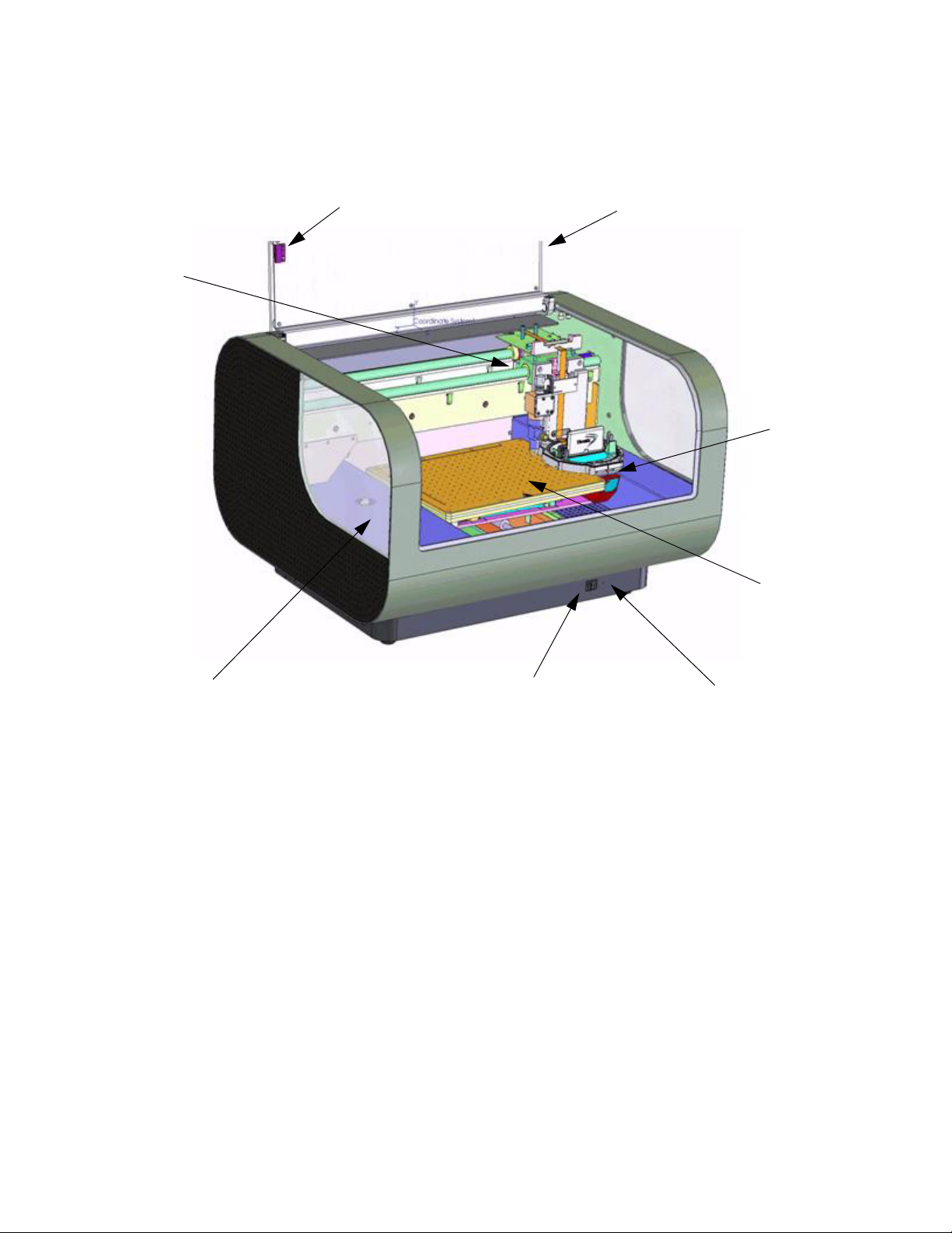
LidLid Closed Sensor
Print
Carriage
Maintenance Station Blotting Pad
Power Switch
Indicator Light
Platen
Drop
Watcher
Figure 1 - 1 DMP 2800
FUJIFILM Dimatix, Inc. Confidential Information Doc. # PM000040 Rev. 01
March 26, 2008
4 Chapter 1 - Introduction
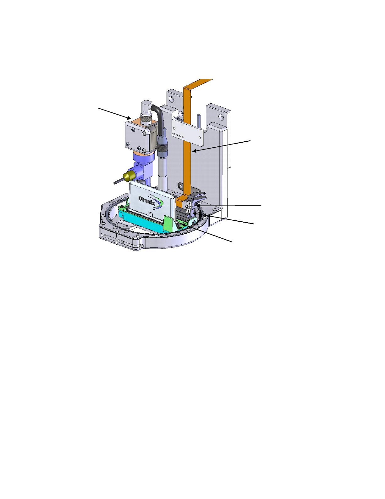
Fiducial Camera
Cartridge Cable
Skew Plate
Holder Latch
Cartridge Holder
Print Carriage
Fiducial Camera
Cartridge Cable
Skew Plate
Holder Latch
Cartridge Holder
Fiducial Camera
Cartridge Cable
Skew Plate
Holder Latch
Cartridge Holder
Print Carriage
The following diagram shows the major components of the DMP Printer Carriage.
Figure 1 - 2 Print Carriage
Doc. # PM000040 Rev. 01 FUJIFILM Dimatix, Inc. Confidential Information
March 26, 2008
Set-Up and Installation
1.0 Unpacking
1.1 DMP
The DMP is shipped in a wooden crate and weighs approximately 45 kg (100 lbs). At a
minimum two people are required to lift it out of the crate and place it onto a surface
sturdy enough to support it without excessive vibrations or oscillations. Be careful not to
put fingers into fan covers on the DMP bottom when lifting.
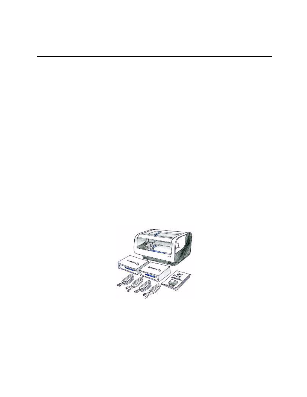
1. Remove the following items from the box:
Chapter
2
•Starter Kit
• Cartridges
• User Manual
•Cables
Figure 2 - 1 DMP items in box
2. Verify contents with checklist
3. Place DMP on an appropriate surface.
FUJIFILM Dimatix, Inc. Confidential Information Doc. # PM000040 Rev. 01
March 26, 2008
6 Chapter 2 - Set-up and Installation
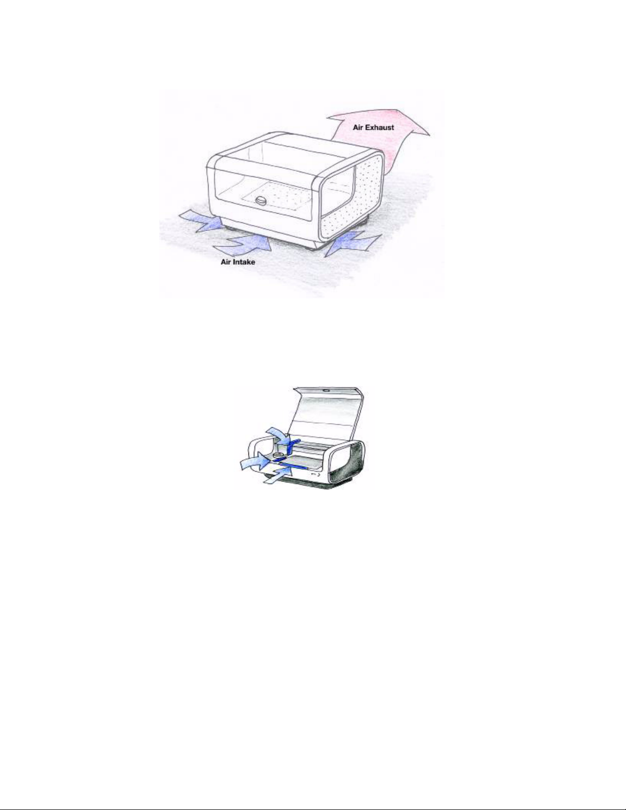
Note: Consider the air flow pattern for proper ventilation.
Figure 2 - 2 DMP air flow
1.2 PC
The PC system is shipped in its original boxes.
4. Remove shrink wrap from DMP
5. Free items that have been secured for shipping
Figure 2 - 3 DMP Packing material locations
a. Remove packing material from under carriage assembly
b. Remove packing material from front and side of platen
Doc. # PM000040 Rev. 01 FUJIFILM Dimatix, Inc. Confidential Information
March 26, 2008
Chapter 2 - Set-up and Installation 7
!
CAUTION
!
CAUTION
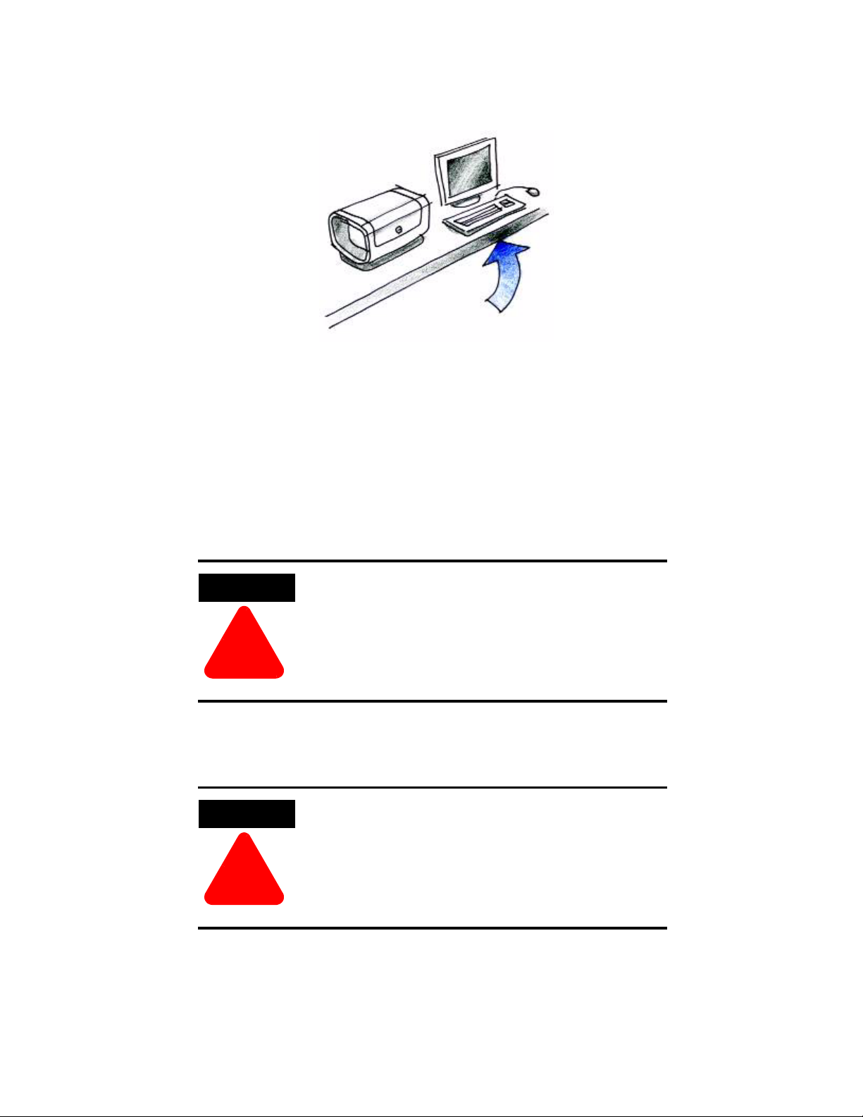
1. Remove them from their boxes and set them next to the DMP
Figure 2 - 4 PC placed next to DMP
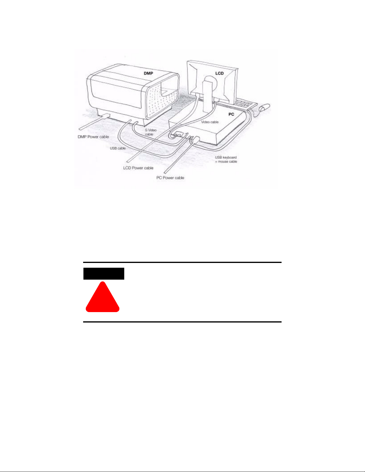
2. Check back of the DMP for USB, S-video, and power connections. Identify
appropriate cables.
3. Connect all cables
a. Power cables to DMP, PC and monitor.
b. USB cable from PC to DMP.
Do not connect DMP to PC through a USB hub.
Do not use USB cables longer than 2 meters.
c. S-video cable from DMP to PC.
d. Monitor video cable to PC.
Do not use video cables longer than 2 meters.
e. Keyboard and mouse cables.
FUJIFILM Dimatix, Inc. Confidential Information Doc. # PM000040 Rev. 01
March 26, 2008
8 Chapter 2 - Set-up and Installation
!
CAUTION
Figure 2 - 5 DMP and PC cabling
2.0 PC Start up
1. Turn on power to PC
2. Allow PC to go through complete start up
Do not change the Regional Settings in the Windows
XP Operating System. The software will not operate
properly.
3.0 Starting Your DMP
1. Make sure DMP lid is closed and all shipping foam is removed
Doc. # PM000040 Rev. 01 FUJIFILM Dimatix, Inc. Confidential Information
March 26, 2008

Chapter 2 - Set-up and Installation 9
Dimatix Drop Manager
2. Turn on power to DMP
a. The light next to the power switch should go on.
Figure 2 - 6 DMP Indicator light
b. Wait at least 5 seconds
4.0 Dimatix Drop Manager
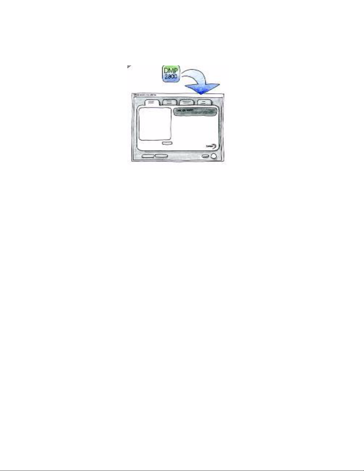
1. The DMP 2800 icon is on the PC desktop.
2. Select the DMP 2800 icon on the screen.
Figure 2 - 7 DMP icon
3. Double click to initiate the Dimatix Drop Manager application.
FUJIFILM Dimatix, Inc. Confidential Information Doc. # PM000040 Rev. 01
March 26, 2008
10 Chapter 2 - Set-up and Installation
4. After initiating the program, click OK to allow the DMP to run through its
initialization sequence.
Figure 2 - 8 Drop Watcher icon on PC screen
Doc. # PM000040 Rev. 01 FUJIFILM Dimatix, Inc. Confidential Information
March 26, 2008
Initial Start-Up Operation
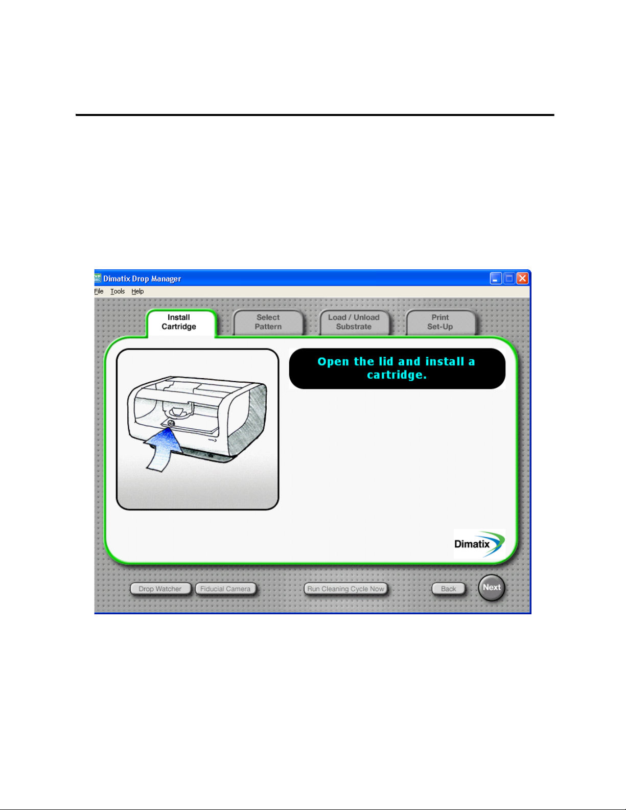
1.0 Install Cartridge
The following steps tell you how to install the Dimatix Model Fluid Cartridge.
Chapter
3
Figure 3 - 1 Install cartridge - Open Lid
1. Prepare the Dimatix Model Fluid Cartridge from the Starter Kit. See Cartridge
Filling instructions in Chapter 9.
2. Lift the DMP lid until it is fully open.
FUJIFILM Dimatix, Inc. Confidential Information Doc. # PM000040 Rev. 01
March 17, 2008
12 Chapter 3 - Start-up
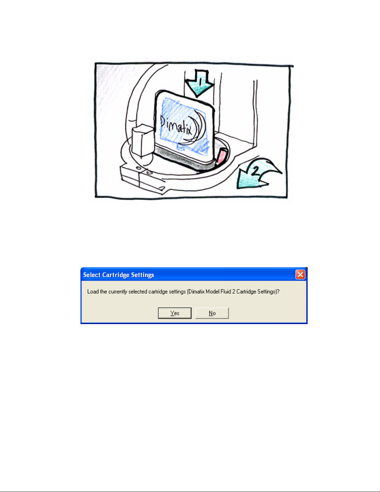
Figure 3 - 2 Install Cartridge
3. Insert the cartridge into the cartridge holder on the carriage with the electrical
connection pads towards the back of the machine matching the connector of the
holder. There is only one way for it to fit. Push it down firmly so that it “clicks”
into place.
4. Pull the cartridge holder latch forward and down until you hear it click and
locks into place. Check to see that the cartridge is sitting flat in the holder.
Doc. # PM000040 Rev. 01 FUJIFILM Dimatix, Inc. Confidential Information
March 17, 2008
Chapter 3 - Start-up 13
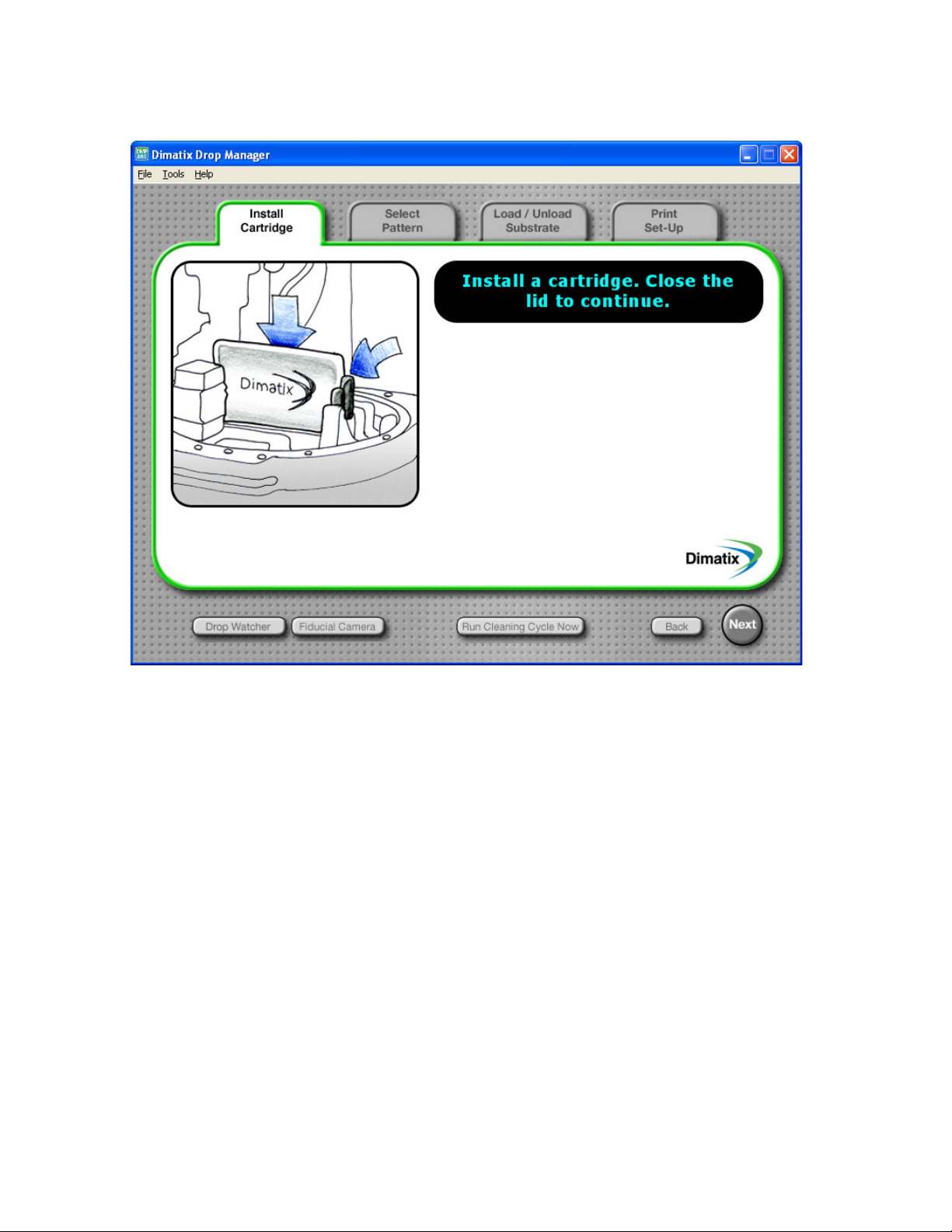
Figure 3 - 3 Installing the cartridge
5. After the cartridge is installed, close the lid. You should hear a pump turn on to
control the meniscus pressure.
6. The following window displays.
Figure 3 - 4 Confirm load cartridge settings window
7. Click Ye s to load the settings for Dimatix Model Fluid 2.
8. After clicking Ye s, the screen advances to the Select Pattern Screen.
FUJIFILM Dimatix, Inc. Confidential Information Doc. # PM000040 Rev. 01
March 17, 2008
14 Chapter 3 - Start-up
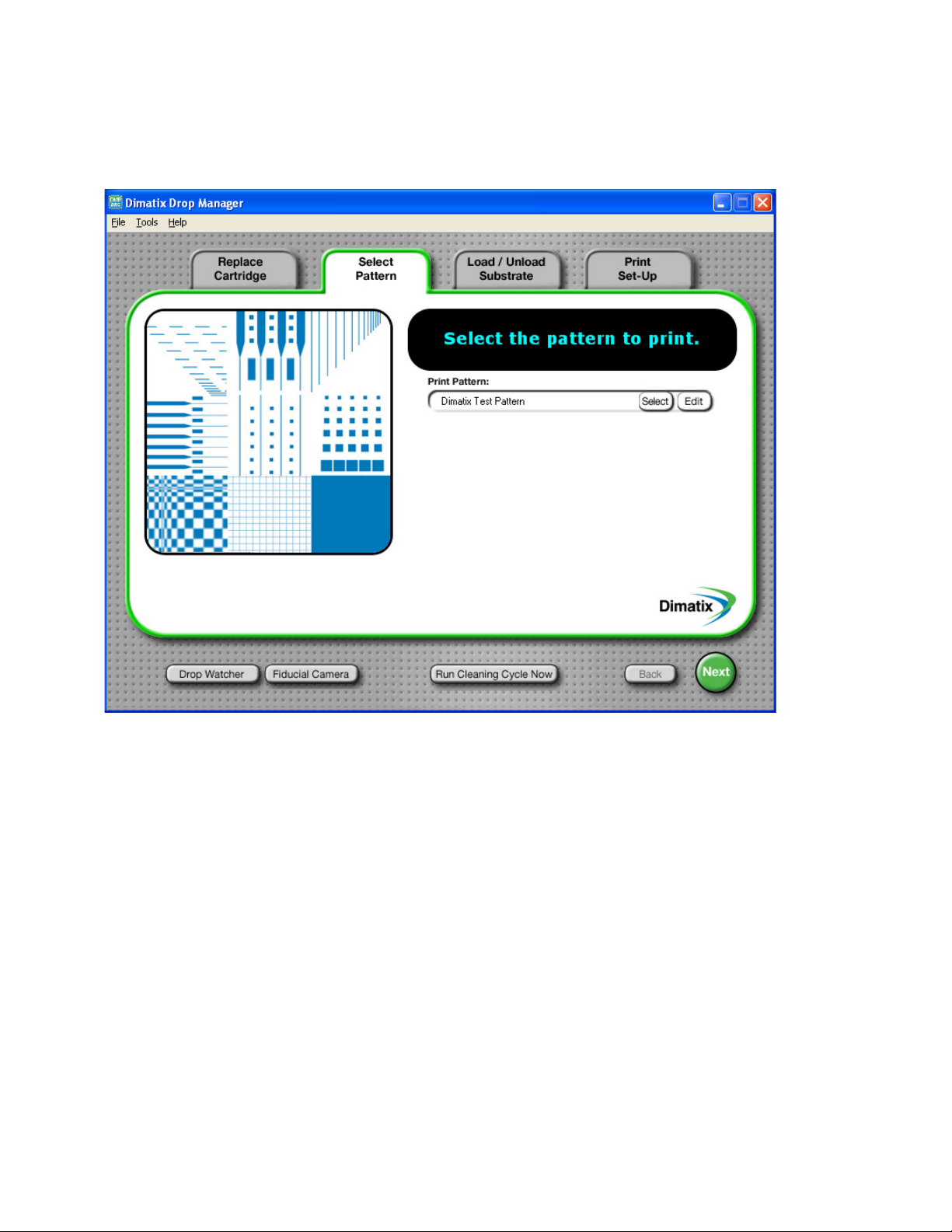
2.0 Select Pattern
The Select Pattern window lets you select a pattern for printing.
Figure 3 - 5 Select Pattern screen
1. The Dimatix test pattern is auto-selected. This is a general use pattern which
lets you see that the system is operating correctly.
2. Click on the Next button to proceed.
3. This takes you to the Load/Unload Substrate screen.
Doc. # PM000040 Rev. 01 FUJIFILM Dimatix, Inc. Confidential Information
March 17, 2008
Chapter 3 - Start-up 15
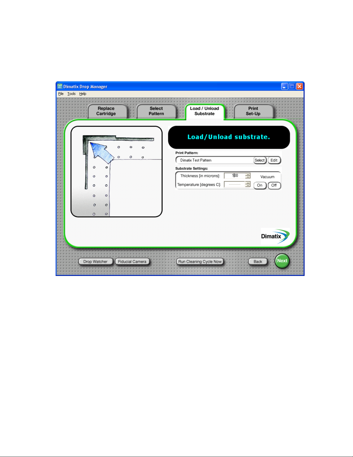
3.0 Load/Unload Substrate
The Load/Unload Substrate tab is where you set the platen temperature and vacuum. It is
also where you must enter the thickness for the intended substrate.
Figure 3 - 6 Load/Unload Substrate screen
FUJIFILM Dimatix, Inc. Confidential Information Doc. # PM000040 Rev. 01
March 17, 2008

16 Chapter 3 - Start-up
!
WARNING
1. To start, use the enclosed piece of glossy ink jet paper to run the test pattern.
This paper is about 250 micrometers thick. Enter 250 (µm) in the box either by
using the up or down arrows on the box or placing the cursor in the box and
typing in the number. The system automatically adjusts the height of the
cartridge to about 1.0 mm above the substrate.
Make sure that you always enter the correct
thickness. Entering a number that is smaller than
the actual thickness can make the carriage crash
into or drag across the substrate causing damage to
the substrate and/or the machine.
2. Open the lid and place the substrate on the platen. Register it to the marks in the
back left corner of the platen which is a general substrate registration position.
This is important to note since it is the approximate location from which the
patterns to be jetted are referenced initially.
3. After placing the substrate on the platen, turn on the platen vacuum by selecting
the Vacuum On button. If your substrate is not very flat, stiff, or smaller than
the platen you may need to cover some of the open vacuum holes with mylar,
adhesive tape, or other material to direct more vacuum to your substrate.
4. If you want to heat the platen, you can enter the temperature in the box by
typing or using the arrows. The system does not print until the platen reaches
the desired temperature. This may take up to 20 minutes for a setting of 60°C.
To run the platen at ambient temperature, click on the down arrow on the box
until you get to a line in the box which represents a setting of “notemperature.”
5. Click on the Next button to go to the Print Set-Up tab.
Doc. # PM000040 Rev. 01 FUJIFILM Dimatix, Inc. Confidential Information
March 17, 2008

Chapter 3 - Start-up 17
4.0 Print Set-Up
The Print Set-Up screen summarizes the previously made selections. This screen displays
the Print Pattern, the Substrate Settings, and the Cartridge Settings.
Figure 3 - 7 Print Set-Up screen
Now you are finally ready to start jetting. The pattern has been selected, the Substrate
Settings have been entered, and the Cartridge Settings have been entered.
FUJIFILM Dimatix, Inc. Confidential Information Doc. # PM000040 Rev. 01
March 17, 2008
18 Chapter 3 - Start-up
1. Click on the Print button and the Print Preview window opens. This window
shows where the print origin is on the platen, where the image to be printed is
and the number of nozzles used to print.
Figure 3 - 8 Print Preview screen
2. Click on the Print button to print the pattern. Your DMP jets the test pattern.
4.1 Nozzle Test Pattern
The 16 line test pattern can be run to see the performance of watch nozzle individually.
This is done from the Print Set-Up screen.
1. Set the Cartridge to 90 degrees.
2. Hold down the Ctrl key on the keyboard while clicking on the Print button at
the bottom right of the screen.
You have successfully completed a print sequence.
Doc. # PM000040 Rev. 01 FUJIFILM Dimatix, Inc. Confidential Information
March 17, 2008

Screen Descriptions
1.0 Main Screen
The Main Menu screen has three pull-down menus: File, Tools, and Help.
Chapter
4
Figure 4 - 1 Main screen
FUJIFILM Dimatix, Inc. Confidential Information Doc. # PM000040 Rev. 01
March 26, 2008

20 Chapter 4 - Screen Description
1.1 File Menu
There are two options from the File menu.
• Printer preview enabled – this item allows you to turn the Print Preview
screen on or off prior to starting a print job.
• Print Info. Logging enabled – this switch enables the printer to write
information about print jobs and the print parameters to a log file in the Print
Logs folder. This folder is found in the directory:
C:\Program Files\Dimatix\\Drop Manager
if you did not change the path during software setup.
1.2 Tools Menu
The following options are available from the Tools drop down menu:
• Cleaning Cycle Editor – for creating a sequence of operations to save as a
cleaning cycle file.
• Pattern Editor – lets you create or modify a drop pattern for printing.
• Pattern Editor (Bitmap images) – lets you import .bmp files or gerber files
into the DMP software.
• Waveform Editor – lets you control shape of the pulse to the nozzle.
• Replace Cleaning Pad – initiates the process for the periodic change of the
cleaning pad.
These options are also available from the Tools menus of other screens. For further
explanations of these options see the appropriate sections of this manual. Consult the
Table of Contents or the Index for the appropriate sections.
1.3 Help menu
• Printer Information – The following screen, Printer Configuration
Information, is accessed from the Help tab on the Dimatix Drop Manager
(DDM) window. It provides information regarding the FPGA and Firmware
version on the DMP, its serial number, as well as actual cartridge and platen
temperature and nozzle meniscus pressure. This information is helpful for
verifying those parameters during operation of the DMP.
Note: The information in the following image is for example purposes only
and may not match the information for your DMP.
Doc. # PM000040 Rev. 01 FUJIFILM Dimatix, Inc. Confidential Information
March 26, 2008

Chapter 4 - Screen Description 21
Figure 4 - 2 Printer Configuration screen
• About – The following screen provides information about the DDM software
version. To exit press the OK button in the lower left.
Figure 4 - 3 DMP About screen
• System Diagnostics – This item opens a window that helps you trouble shoot
different errors that might occur during operation of the printer, as described in the
System Diagnostic section later in this manual.
FUJIFILM Dimatix, Inc. Confidential Information Doc. # PM000040 Rev. 01
March 26, 2008

22 Chapter 4 - Screen Description
An additional program feature is a link to the FUJIFILM Dimatix Web site. If your PC
is connected to the internet, click on the Dimatix logo on the bottom right of the various
DDM screens to automatically connect to the Web site.
2.0 Cartridge Settings
In the start up procedure we showed you how to select a file with a preset cartridge
setting that had been predetermined for the test fluid by FUJIFILM Dimatix. Now we
will get into the details of the settings and the editor screens.
You can enable Advanced Cartridge Settings using the Tools menu Enable
Advanced Features. Additional parameters are added to the cartridge settings.
By clicking on the Edit button on the Cartridge Settings box, the following screen
displays.
Figure 4 - 4 Cartridge Settings screen
On the above window you can load a previously created cartridge setting file from the
File menu. Here you can also save cartridge setting files.
Doc. # PM000040 Rev. 01 FUJIFILM Dimatix, Inc. Confidential Information
March 26, 2008

Chapter 4 - Screen Description 23
2.1 Waveform Tab
From the Waveform tab the voltage of each nozzle can be individually adjusted by typing
a number in the individual nozzle box or by clicking on the up or down arrow in the nozzle
box. You may want to do this to adjust drop velocities of individual nozzles, since velocity
is a function of voltage. You can also change all of them simultaneously with the Adjust
All arrows. (See Wavefrom Editor for effects of voltage on jetting). The Increment
number is the amount the voltage will change with one click on the up or down arrow
buttons. The Waveform tab displays the active waveform. You can load previously saved
waveforms using the Select button or you can edit the active waveform using the Edit
button.
Note: Once you have established the settings for a particular fluid, you may have
to adjust the voltages for a new cartridge to match the drop velocity of a
previous cartridge. See Drop Watcher for instructions on setting drop
velocity.
Note: Tickle Control can only be accessed by opening the cartridge settings of the
Print Set-Up screen in the DDM main window. Opening the cartridge
setting via the Drop Watcher does not allow you to change tickle control
as it is displayed in gray.
The Tickle Control enables and controls the low amplitude pulse that is given to the
nozzle periodically simply to move the meniscus slightly but not eject a drop. For certain
jetting materials this prevents the nozzle from “skinning over” due to fluid evaporation.
The “tickle” function is completely adjustable and, is very important for some fluids and
not required for others. Test this function with your fluid before setting it as a default.
The low amplitude pulse that tickle control sends to the nozzle can be modified in the
Waveform Editor window as the non-jetting waveform. The frequency set in tickle
control is always active when the printer is not printing. This includes the times during
which the carriage is above the maintenance pad, on its way to the selected print area, or
on its way back from one print pass to start the next pass. However, during printing, the
tickle frequency is the same as the jetting frequency set with the waveform editor. So
during one print job, the printer repeatedly switches between the two pulses.
FUJIFILM Dimatix, Inc. Confidential Information Doc. # PM000040 Rev. 01
March 26, 2008

24 Chapter 4 - Screen Description
2.2 Cartridge Tab
If you click on the Cartridge tab in the Cartridge Settings window, the following
screen displays.
Figure 4 - 5 Cartridge Settings – Cartridge Tab
This screen lets you set the Cartridge Temperature. This is usually used when the
fluid is too viscous to jet and you need to lower the viscosity by raising the temperature
to get the desired jetting performance.
Also on this window is the setting for Meniscus Vacuum. Ink jetting devices operate
under negative pressure to keep the meniscus at the edge of the nozzle. You may need
to adjust this depending on the viscosity and surface tension of your fluid. Four inches
of water is a typical value. Having the correct meniscus vacuum level usually affects
the high frequency performance of the fluid you are jetting.
The Jets to Use function allows you to select the range of nozzles you wish to use to jet
your pattern, if you want to use fewer than all sixteen. The software automatically
compensates for the number of nozzles used but the nozzles selected can only be one
series of adjacent nozzles.
Doc. # PM000040 Rev. 01 FUJIFILM Dimatix, Inc. Confidential Information
March 26, 2008

Chapter 4 - Screen Description 25
The Cartridge Print Height sets the distance of the printhead above the substrate. It can
be adjusted from .250 mm to 1.50 mm. Take care to set the Substrate Thickness and
Cartridge Print Height accurately to avoid hitting the substrate during printer operation.
2.3 Cleaning Cycles Tab
The Cleaning Cycles tab lets you control how the print cartridge is cleaned before,
during, and after printing. Some fluids do not need periodic maintenance, while others
need a high amount of maintenance to keep nozzles clear and functioning properly.
Figure 4 - 6 Cartridge Settings – Cleaning Cycles tab
FUJIFILM Dimatix, Inc. Confidential Information Doc. # PM000040 Rev. 01
March 26, 2008

26 Chapter 4 - Screen Description
• Select button – lets you select an existing cycle in the cleaning cycle folder.
• Edit button – lets you edit that cycle with the editor window.
• Start of Printing – refers to the cleaning you want to do at the beginning of the
print. Select a cycle you wish to run to enter one in that box or you can edit an
existing file with the Edit button.
• During Printing – refers to the cleaning cycle you want to run while printing
your pattern. This can be set to run every so many number of Bands (one cycle
of the carriage across the platen and back is a band) or every so many Seconds
of printing time. Select a cycle you wish to run by clicking on Select and
choose one from the folder or you can edit an existing one with the Edit button.
Whichever is more frequent between Run every x Bands OR Seconds
(depending on printing speed) is the cycle that is used During Printing.
• End of Printing – refers to the cleaning you would like to do at the end of your
printing. Select a cycle you wish to run to enter one in that box or you can edit
with the Edit button.
• While Idle – refers to any cleaning you would like to do while the system is not
printing but is on and you have a cartridge installed. Select a cycle you wish to
run to enter one in that box or you can edit with the Edit button.
• None – can be entered into any box that would have a file name to indicate not
to do any cleaning during that time.
• 0 – can be entered where numbers are required to indicate not to run that cycle.
3.0 Cleaning Cycle Editor
The Cleaning Cycle Editor is run by clicking the Edit button next to any of the
cleaning cycles or by selecting Cleaning Cycle Editor from the Tools menu in the
Cartridge Settings window or the DDM Main screen. The Cleaning Cycle Editor can
also be accessed from the Cleaning group in the Drop Watcher window. From this
editor you can create sequences of operations that can be saved as a cleaning cycle file.
Doc. # PM000040 Rev. 01 FUJIFILM Dimatix, Inc. Confidential Information
March 26, 2008

Chapter 4 - Screen Description 27
Refer to the Cartridge Maintenance section in the back of the manual for more details.
The default cleaning cycle, Spit Purge Spit, is shown below.
Figure 4 - 7 Cleaning Cycle Editor screen
• Spit – refers to jetting the nozzles for the designated time at the given frequency.
• Purge – refers to pushing fluid out through the jetting device with pressure
(system is preset to 5psi). This process is usually used to get air out of the jetting
device.
• Blot – refers to the cartridge simply coming down and making contact with the
cleaning pad for the designated time. As the nozzle plate is recessed into the
cartridge it does not touch the cleaning pad. The cleaning pad gets close enough to
absorb fluid residue on the nozzle plate.
Note: It is important to make sure that the cleaning pad is not saturated or
clogged to ensure good removal of the fluid from the nozzles after purging
or spitting.
• Delay time – is the time after the cleaning before going to the next step in the
cycle.
A cleaning cycle can be very simple, such as a “2 second blot” or they can consist of
several combinations of actions (spitting, purging, and blotting) with varying times.
FUJIFILM Dimatix, Inc. Confidential Information Doc. # PM000040 Rev. 01
March 26, 2008

28 Chapter 4 - Screen Description
Here is how to create a cleaning cycle:
1. Click on the Spit, Purge, or Blot.
2. Then enter a number or use the arrows for the Time, Frequency or Post Delay
that you want.
3. Click the Add button to enter it into the table and incorporate it into the cycle.
4. If you want another action to occur next, simply repeat the process.
5. If you want to delete a step, highlight it in the table by clicking on it, then click
the Delete button.
6. When you have built your cleaning cycle, Save it with a name that describes
what it does using the Save As from the File menu.
If desired you can run the cleaning cycle you just created by clicking on the Run Now
button in the DDM main window.
Doc. # PM000040 Rev. 01 FUJIFILM Dimatix, Inc. Confidential Information
March 26, 2008

Chapter 4 - Screen Description 29
4.0 Waveform Editor
The waveform editor is where you make changes to the waveform by adding or deleting
segments, make changes to the segments, or rescale a waveform.
Figure 4 - 8 Waveform Editor screen
This is the control screen for the electrical signal that triggers the drop ejection. The signal
consists of multiple segments (four in the above example). To adjust a segment, simply
point your with your mouse and click on it. The selected segment changes from blue to
red.
The Waveform Basics chapter, later in this manual, describes how changing the waveform
affects drop ejection. There is an application note available through
E-Commerce on the FUJIFILM Dimatix home page that elaborates on this topic.
FUJIFILM Dimatix, Inc. Confidential Information Doc. # PM000040 Rev. 01
March 26, 2008

30 Chapter 4 - Screen Description
4.1 Individual Segment Controls
In this group you have several parameters at your control. If you want to modify a
segment, click on that segment in the graph with the mouse to highlight it. Now modify
the parameters for it by typing in a number, using the up/down arrows or slider bar.
Level – This is the percent of the amplitude relative to the value specified in
the Cartridge Settings Waveform screen.
Slew Rate – This is the slope of the line in the waveform during voltage
ramps.
Duration – This is the length (in time) of the segment.
You can add waveform segments to optimize drop ejection. Click on the segment that
you want to place a new segment in front of and click the Add button. You can now
modify that segment as you would the others. You can delete a segment simply by
clicking on it and selecting the Delete button.
Note: The duration and the level of a segment can also be modified by holding
down the mouse button and moving the mouse. Hold down the left
mouse button and move the mouse up or down to modify the level of a
segment. Hold down the right mouse button and move the mouse left or
right to adjust the duration of a segment. These instructions are in the
box to the right of the graph.
4.2 Overall Waveform Controls
Duration Scaler – This feature allows the user to easily scale the entire
waveform pulse width at once. This is useful when you are using fluids with
different densities. Fluids with higher densities generally need longer
pulses. Enter a number in the box then click the Rescale Waveform button.
The entire waveform’s width changes by multiplying its current width by
the Rescale number. For example, if you enter 1.1 in the Duration Scalar
box, it adjusts each waveform segment’s length proportionally to multiply
the waveform’s overall width by 1.1, which is a 10% increase.
Width – This box displays the overall pulse time width for the entire
waveform.
Maximum Jetting Frequency – The maximum jetting frequency is
established by the user during initial fluid characterization using the drop
watcher system. During initial characterization the maximum frequency of
80 kHz should be entered into the waveform file being loaded. This value
dictates the scale for the Jetting Frequency Maximum in the Drop
Watcher window. After the user has established the maximum sustainable
jetting frequency in the drop watcher it is essential to ensure the maximum
Doc. # PM000040 Rev. 01 FUJIFILM Dimatix, Inc. Confidential Information
March 26, 2008

Chapter 4 - Screen Description 31
!
CAUTION
jetting frequency setting in the waveform file does not exceed the frequency
used to optimize jetting in the drop watcher.
If you fail to limit this frequency setting to the
maximum frequency used during drop watcher
evaluation you can create a situation where the
system uses one frequency for drop watching and
another for printing. This invalidates the correlations
between visual observations in the drop watcher and
actual printing performance!
4.3 Non-Jetting Waveform
The Non-Jetting Waveform can be modified just like the jetting waveform. The
instructions are in the box to the right of the graph.
4.4 Jetting Waveform vs. Non-Jetting Waveform
When the printhead travels over the print area, the software automatically tells it which
nozzles to jet and which are idle. The idle nozzles get the amplitude signal displayed in the
Non-Jetting Waveform chart. The jetting nozzles get addressed with the Jetting
Waveform.
The Non-Jetting Waveform is also the pulse signal that the Tickle Control sends to the
printhead during non-printing times. Such as when the carriage is above the maintenance
pad, or when it is moving to the defined print area or moving between two print passes.
Raising the amplitude of the non-jetting waveform above the default zero condition can
help some fluids to start-up more reliably.
5.0 Replacing Cleaning Pad
Located in the Tools pull down menu on the DDM main screen is a feature called Replace
Cleaning Pad. You will want to replace the cleaning pad with a new one when it gets
filled with fluid or clogged by fluid residue and does not effectively blot the nozzle surface
of the cartridge, or you are changing cartridge fluids and don’t want cross contamination
from contacting the previous material on the cleaning pad.
FUJIFILM Dimatix, Inc. Confidential Information Doc. # PM000040 Rev. 01
March 26, 2008

32 Chapter 4 - Screen Description
IMPORTANT
IMPORTANT
To replace the cleaning pad select Replace Cleaning Pad from the Tools menu. The
cartridge moves to allow access to the pad.
Figure 4 - 9 DDM – Moving the Cartridge screen
DO NOT open the printer lid until told to do so.
Opening the lid while the printer is in motion
necessitates a re-initialization of the printer.
Doc. # PM000040 Rev. 01 FUJIFILM Dimatix, Inc. Confidential Information
March 26, 2008

Chapter 4 - Screen Description 33
Figure 4 - 10 DDM – Open the lid screen
Open the lid and replace the pad.
Figure 4 - 11 DDM – replace cleaning pad screen
FUJIFILM Dimatix, Inc. Confidential Information Doc. # PM000040 Rev. 01
March 26, 2008

34 Chapter 4 - Screen Description
IMPORTANT
IMPORTANT
Replace the pad by:
1. Taking the top clear cap of a new Cleaning Pad assembly and push it down on
the old pad until you hear a click and then simply pull it out.
2. Insert the new pad and holder by pushing the pad and holder down into the spot
where the old one was until you hear a click.
Figure 4 - 12 Cleaning Pad replacement
Be careful not to remove the cleaning pad by itself.
This can damage the springs holding the receptacle
which will then not position it correctly. Do not
touch the top of the new maintenance pad with your
fingers.
When the lid is closed the carriage moves back to the cleaning station.
Doc. # PM000040 Rev. 01 FUJIFILM Dimatix, Inc. Confidential Information
March 26, 2008

Pattern Printing
If you are printing a pattern on a substrate that you will either remove or reposition, or you
want to change cartridges in between printing two layers, be sure to set the print origin
before printing the first pattern. This is done using the Fiducial Camera. If you change
cartridges, you also have to perform a drop offset adjustment.
1.0 Select Pattern
The following screen allows you to pick a print pattern file that has already been created,
or to create a new one.
Chapter
5
Figure 5 - 1 Select Pattern screen
FUJIFILM Dimatix, Inc. Confidential Information Doc. #PM000040 Rev. 01
March 26, 2008

36 Chapter 5 -Pattern Printing
Microscope
Slide 25K Array
Line Array
1 mm Hatch 1 cm Solid
Dimatix Test
Pattern
From the Select button in the Print Pattern box you saw earlier that there are several
predefined standard pattern files.
1.1 Predefined Standard Patterns
Figure 5 - 2 Predefined test patterns
2.0 Create Your Own Pattern
The Pattern Editor lets you create or modify patterns of drops for printing, and easily
repeat them over the entire substrate if needed. The basic pattern, at the lowest level,
(Pattern Block Array) is a collection of rectangles that are called pattern Block Drop
Positions. Each of these rectangles may be small enough to represent a single drop, or
thin enough to represent a line of drops, or large enough to represent a fully filled-in
rectangular area.
In all cases, X increases to the right, and Y increases toward the front of the printer. All
dimension parameters are in millimeters except for the Drop Spacing, which is in
micrometers. All dimensions entered into the pattern generator are rounded onto the
Drop Spacing.
Doc. #PM000040 Rev. 01 FUJIFILM Dimatix, Inc. Confidential Information
March 26, 2008

Chapter 5 -Pattern Printing 37
By selecting the Edit button on the Select Pattern screen the following screen appears:
Figure 5 - 3 Pattern Editor screen
2.1 Substrate
The Dimensions is the total area to print. Generally most people jet on only a single
substrate. But you could place several smaller substrates on the platen and jet on all of
them at once. Verify that the total area is not larger than your substrate.
The Leader Bar is a vertical bar that can be jetted to the left of your pattern by checking
the Enable box. This is a commonly used procedure in ink jet printing to pre-jet nozzles to
FUJIFILM Dimatix, Inc. Confidential Information Doc. #PM000040 Rev. 01
March 26, 2008

38 Chapter 5 -Pattern Printing
keep them active and their drop velocity uniform to improve pattern quality. The
Width of it and the Gap of the leader bar can be entered in the boxes.
Note: Your pattern is automatically shifted to the right when you create a
leader bar by the amount of gap and width. It is not automatically
returned to its original position if you later decide to disable the leader
bar.
The Drop Spacing is the center to center distance from one drop to the next in X and Y
position to create the pattern. Although this value can be adjusted in 1 μm increments it
is always rounded to the next 5 μm increment as soon as you start printing this pattern
file. The X spacing is controlled by the x axis encoder, while the y axis is controlled by
the cartridge angle.
Note: For the first print outs of Dimatix Model Fluid 2 on ink jet paper a drop
spacing of about 20 μm usually gives good printing results.
The Layers box feature allows you to reprint the same pattern over itself automatically.
The Count number is the number of times you want to print the pattern and the
Interlayer Delay is the delay time between each layer, additional to the amount of time
spent doing any before print or after print maintenance on the cartridge.
If you click on the Preview Drops button, a window pops up showing the area you
have designated. The total area of the window represents the platen. If the substrate
area you entered is smaller than the platen it shows as a beige shape inside the white
area.
Doc. #PM000040 Rev. 01 FUJIFILM Dimatix, Inc. Confidential Information
March 26, 2008

Chapter 5 -Pattern Printing 39
Your Pattern Block Array area is delineated within the substrate area outlined.
Figure 5 - 4 Pattern Block Array
2.2 Pattern Block Array
In the Pattern Block Array box enter the point on your substrate where you want the
pattern to start printing in X and Y, referencing from the print origin. Then enter the X
width and Y height of the block you want to make. The X and Y sizes entered should be
at least large enough to enclose the collection of rectangles defined in the Pattern Block
Drop Positions (see below).
Note: The default print origin is approximately -1 mm, 7 mm (x,y) from the 0,0
corner scribed in the back left of the platen. See the Fiducial Camera
section of this manual for more information.
To print a repetitive array of the pattern block in your print area, enter the X and Y Pitch
dimensions. The Pitch is the distance from the start of one pattern to the next. Enter the
number of patterns (X count) to print in the horizontal direction, and the number of
patterns (Y count) to print in the vertical direction.
FUJIFILM Dimatix, Inc. Confidential Information Doc. #PM000040 Rev. 01
March 26, 2008

40 Chapter 5 -Pattern Printing
2.3 Pattern Block Drop Position
The pattern generator works with one or more user-entered rectangles of X width and Y
height. There are two ways of creating a feature in a Pattern Block Array. You can
enter values manually in a table or you can use the mouse to create features.
To manually create features enter the dimensions in the Pattern Block Drop Position
group as follows and click the Add button. It is placed in the table on the bottom of the
window.
• Enter the position (X and Y) where you want to place the first drop in your
Pattern in the Pattern Block field.
• Then enter the length and height of the feature you want to create. For lines,
enter the width height of the line that you want. For example, for a horizontal
line you would enter how long you want it to be in the x direction (X, width),
maybe 10 mm, and for 200 μm tall you would enter 200 micrometers for the Y
Height. For the same vertical line, it would be 200 μm X width, and 10mm Y
height. To define a feature that is a single row of dots or a single dot, use a
dimension or dimensions smaller than the value defined under Drop Spacing.
• The Increment Value is the value at which you want the dimensions to change
with each click of the arrow buttons. For example an increment value of 1.000
changes the dimension 1 mm for every click of the arrow. The increment value
gives you a convenient way to generate a set of related rectangles.
2.3.1 Draw feature
You can also very easily create a feature in the pattern block by placing the cursor on
the Preview Drops window, place the cursor in a Block, hold the Shift key down and
point, left click, and drag to create a rectangle. A line containing the values of your
newly created feature are automatically added to the table in the Pattern Block Drop
Position box. This is a fast way to roughly create your pattern, later on you can edit it
out by changing the values manually in the Pattern Block Drop Position table.
Note: Only those rectangles that are added to the table on the bottom of the
pattern editor window get saved once you are done creating your
pattern.
If you click on the Preview Drops button, a window pops up which shows you the
pattern. When you click on a line of data in the table specifying a feature, that feature
shows up in red on the Preview Drops screen. You can zoom in on the feature by
clicking on the + Magnifying Glass button to where you can see the individual spots.
When you zoom in it is best to have Show All Patterns deselected to reduce data
crunching. You can continue zooming in until you see the grid background. Then when
you hold the Ctrl button on the keyboard and point and drag the right mouse button on
your feature of interest you can zoom in and it stays centered on the screen. You can
Doc. #PM000040 Rev. 01 FUJIFILM Dimatix, Inc. Confidential Information
March 26, 2008

Chapter 5 -Pattern Printing 41
also draw new features into the pattern by holding down the Shift button and dragging a
rectangle with the mouse.
Figure 5 - 5 Preview Drops screen
FUJIFILM Dimatix, Inc. Confidential Information Doc. #PM000040 Rev. 01
March 26, 2008

42 Chapter 5 -Pattern Printing
Figure 5 - 6 Zoomed In area
You can see grey lines on the screen which represent the pattern created in the pattern
generator. The dots are actually where the drops are placed as the dimensions are
rounded to fit on the grid you have defined in the Drop Spacing.
If you highlight a line in the table and click the Add button you duplicate that feature. It
is jetted right on top of itself unless you change the X and Y Start values, which you
can do by highlighting that data line in the pattern generator table and then changing
the numbers in the appropriate boxes.
The Preview Spot Size box lets you enter the diameter of the spot that a single drop
makes on your substrate. This is helpful to visualize how much separation or overlap of
drops you have in the pattern features depending on their size and the drop spacing
used. When reviewing the pattern to see how the features match the grid or how
adjoining features line up set the Preview Spot Size to 10 μm.
The Enable Spot Size feature allows you to zoom in on the image and view the
individual spots of your pattern. Putting a check in the box by clicking on it enables it.
Click on it to disable it to view all of the patterns.
The Show All Patterns feature enables you to see all the patterns on the substrate when
checked.
The 1x button displays the pattern on the screen very close to its actual size.
Doc. #PM000040 Rev. 01 FUJIFILM Dimatix, Inc. Confidential Information
March 26, 2008

Chapter 5 -Pattern Printing 43
The figure below illustrates how the pattern editor works. The print origin shifts if a leader
bar gets used. If no leader bar is used the print origin is at the very top left of the pattern.
The figure also shows that the leader gets only printed in those passes of the print head
where the image has content. The leader bar might therefore have gaps in y direction.
Figure 5 - 7 Pattern Editor at work
2.4 Drop Spacing
The drop spacing is the center to center distance in X and Y of the drops that the DMP
deposits to create the pattern. Drop spacing is adjustable between 5 and 254 μm in one
micron increments. It toggles with the arrows on the box in five μm increments. For
example, with a 50 μm drop spacing, the pattern generator places drops 50 μm apart in X
and 50 μm apart in Y to fill in your pattern. So, for a 100 μm wide, 10 mm tall vertical
line, the system places 3 drops in the X direction (one for the first edge, another at 50 μm,
and another at 100 μm for the next edge) by 2,001 drops tall. The drop spacing therefore
determines your resolution or density in the X direction and determines the angle at which
the cartridge must be set to get the same resolution or density in the Y direction. The drop
spacing parameter is most useful for altering the fill density (amount of jetted ink per area)
of lines and rectangles, or it may be used to create rows of individual drops which are
spaced closer together than 254 μm.
FUJIFILM Dimatix, Inc. Confidential Information Doc. #PM000040 Rev. 01
March 26, 2008

44 Chapter 5 -Pattern Printing
IMPORTANT
IMPORTANT
3.0 Bitmap and Gerber File Printing
To import .BMP files or Gerber files into the DMP Software, select Tools on the DDM
main window. Then select Pattern Editor (Bitmap images). This opens the Image to
Pattern Converter window. Then under File, select Open BMP or Open Gerber to
open your file. The Gerber Tools option must be loaded in the system for Gerber File
conversion.
3.1 Gerber Files
To open a Gerber file, set the Drop Spacing you want to use to print the image and
then select Open Gerber from the File menu. Then select the Gerber file you want.
The Gerber file is processed into a pattern file at the selected drop spacing resolution.
All of the controls operate as if it was a .BMP file with the exception of drop spacing
and X width, Y height. Since a Gerber file is resolution independent, changing the drop
spacing does not change the dimensions of the output.
If you change the drop spacing you must then save
the file for it to be processed at the new drop
spacing.
Doc. #PM000040 Rev. 01 FUJIFILM Dimatix, Inc. Confidential Information
March 26, 2008

Chapter 5 -Pattern Printing 45
Figure 5 - 8 File Conversion screen
3.1.1 Substrate Tab
The Substrate Tab has the following features:
• Substrate Dimensions – this is the calculated minimum size of a substrate that is
needed to print the pattern
• Leader Bar – this is the same feature as for pattern files. It is a vertical bar that
you may add to your pattern to enhance print quality.
• Drop Spacing – this is the same as for pattern files, it is the spacing of the drops
(center to center) in x and y that are jetted to create the pattern.
• Layers – this is the same as for pattern files and allows re-printing the same
pattern over itself several times (Count) with or without a delay (Interlayer
Delay) between.
FUJIFILM Dimatix, Inc. Confidential Information Doc. #PM000040 Rev. 01
March 26, 2008

46 Chapter 5 -Pattern Printing
The Full, Fit, Zoom, and Pan enable movement and zooming of the image. When an
image is first loaded it zooms to Fit. This shows the full extents of the bitmap. Clicking
the Full button zooms in on the image to the point where each pixel in the .BMP file is
displayed as a pixel on the screen. The form may be resized to provide a larger preview.
If the Zoom button is selected, then clicking and dragging the left mouse button over
the image creates a zoom window. When the mouse is released the image zooms to the
selected area. If Pan is selected, clicking the left button and dragging in the image
moves the viewable image in the window. These controls can be used to view the high
resolution data and aid in selecting the reference point.
The Tiled Preview button allows viewing of all the patterns to be printed.
Figure 5 - 9 Placement/Tiling Tab
3.1.2 Placement
X Start, Y Start is the position relative to the print origin that the pattern starts.
X Width, and Y Height is the calculated size of the pattern.
Doc. #PM000040 Rev. 01 FUJIFILM Dimatix, Inc. Confidential Information
March 26, 2008

Chapter 5 -Pattern Printing 47
3.1.3 Tiling
This is used to make multiple print copies of the same pattern. The Pitch is the distance
from the beginning of one pattern to the next as set in X Pitch and Y Pitch. The number of
patterns is set by the Count.
Figure 5 - 10 Reference Point Tab
3.1.4 Reference Point
The X Ref, Y Ref, Locate Ref Point, and Set Ref Point provide an additional way to
position the image by aligning a point in the image to a specific point on the substrate (a
FUJIFILM Dimatix, Inc. Confidential Information Doc. #PM000040 Rev. 01
March 26, 2008

48 Chapter 5 -Pattern Printing
point is selected in the image and a corresponding point is selected in the Fiducial
Camera window).
• To print using a Reference Point in your image, check the box Use Reference
Point.
• To set a reference point, first locate the part of the image you wish to align to by
either using Zoom or Pan. Click Set Ref Point. Then place the cursor on the
point in the image and click on it with the left mouse button. Or, if you know
the dimensions for the Reference Point you can type them in directly into the X
Ref, Y Ref boxes then click Locate Ref Point. This takes you to that specific
point in the image. The cross hair cursor that displays the reference point shows
where the pattern is printed. You can make fine adjustments by clicking the
arrow up/down buttons next to the X Ref and Y Ref boxes. You must save the
file once you select the point for the DMP to utilize it.
• To complete the Reference Point usage, go to the Fiducial Camera window
(see Fiducial Camera section). Click on the Fiducial Camera button on the
main DDM window to open the fiducial camera.
• In the Tools menu of the Fiducial Camera window click on the Set Reference
Point button.
• Find the point on your substrate where you want to place your selected image
Reference Point by moving the camera to the desired position. Place and click
the cursor on your point.
• Click the Use Reference Point box on the Fiducial camera window.
• Do not close the Fiducial Camera window before you print. It must stay open.
Click the Print button on the main DDM window Print Set-Up tab.
The X Width and Y Height values are filled in when a file is loaded. The size is based
on the image size and the drop spacing. Bitmap files must be printed at the drop
spacing (resolution or dpi) they were created for, or the image size changes
accordingly. To convert from drop spacing to resolution:
Drop Spacing [dpi] = 25400 / Resolution [μm]
A status bar at the bottom shows the current zoom factor, the location of the upper left
of the preview, and the image size. The current cursor position is also displayed.
Doc. #PM000040 Rev. 01 FUJIFILM Dimatix, Inc. Confidential Information
March 26, 2008

Chapter 5 -Pattern Printing 49
Figure 5 - 11 Reference point settings
When all of the parameters are correct you must save the file as a pattern file (it has a .ptf
extension). The pattern file is what can be selected from the main form or the fiducial form
to print.
4.0 Print Preview
The print preview can be disabled or enabled in the DDM main window File menu. If it is
on, it shows a preview before the printing starts. The title bar of the dialog tells if the
reference or printing origin is being used. The print origin (or reference point) is marked
with a cross hair. The leader bar is shown if it is enabled.
The preview is sizable so it can be made full screen for more detail. Remember, the platen
area is not the substrate. The user has to make sure the substrate is placed correctly on the
FUJIFILM Dimatix, Inc. Confidential Information Doc. #PM000040 Rev. 01
March 26, 2008

50 Chapter 5 -Pattern Printing
platen and that it fits the image they are going to print. The preview is meant to make
sure that the origin and tiling are set correctly.
The following are some sample screen shots using the reference point and leader bar on
a tiled pattern. The reference image used in this example is the lower right one of the
array and there is a leader bar:
Figure 5 - 12 Print Preview – Reference point
Doc. #PM000040 Rev. 01 FUJIFILM Dimatix, Inc. Confidential Information
March 26, 2008

Chapter 5 -Pattern Printing 51
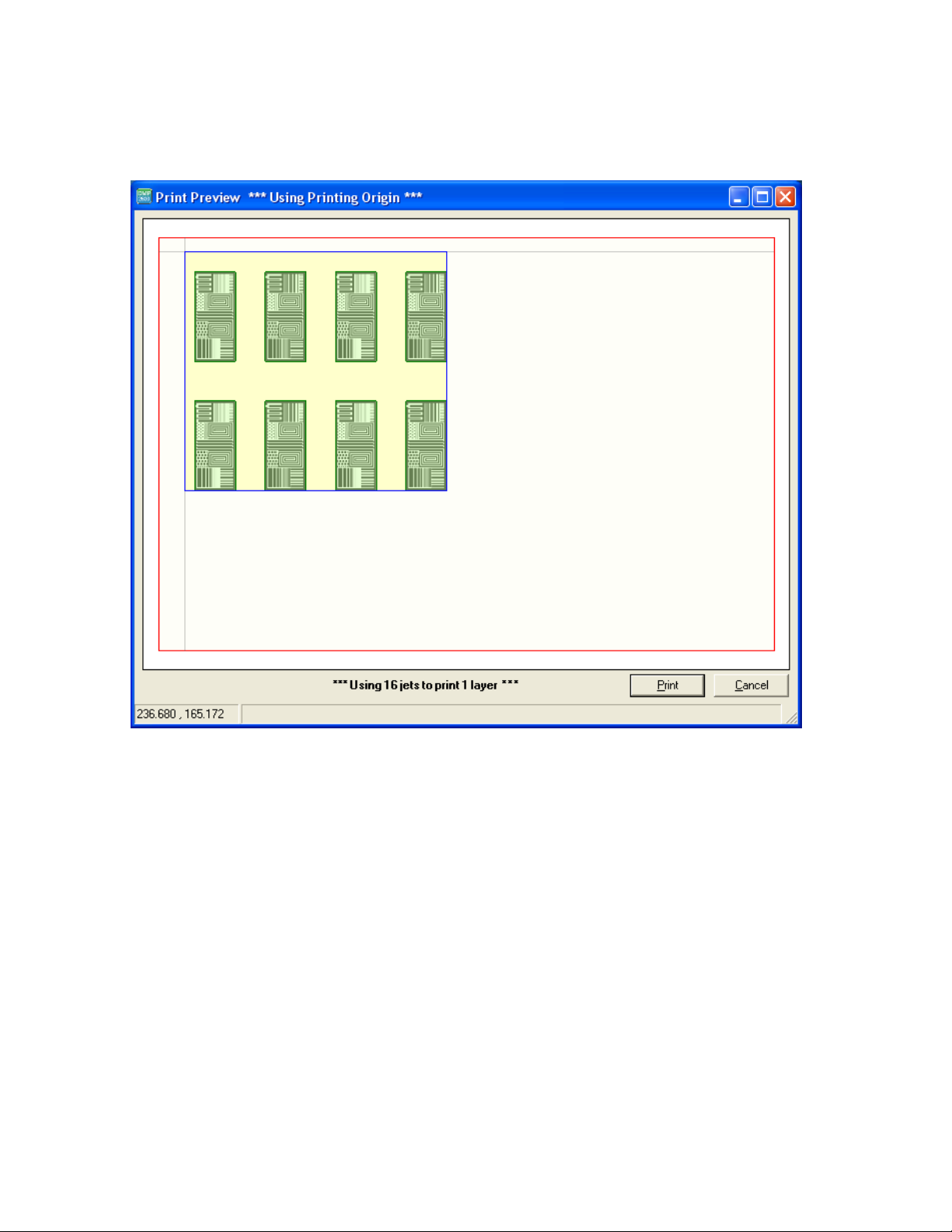
This example shows a tiled array, using a print origin, without a leader bar.
Figure 5 - 13 Print Preview – Print Origin without leader bar
FUJIFILM Dimatix, Inc. Confidential Information Doc. #PM000040 Rev. 01
March 26, 2008

52 Chapter 5 -Pattern Printing
A tiled image with a bad reference point.
Figure 5 - 14 Using a bad reference point
The error message you get if you try to print from an origin that takes the image off the
printable platen area.
Figure 5 - 15 Image area message
5.0 Cartridge Mounting Angle
Before you jet your pattern, the system calculates the angle to set the cartridge
determined by the drop spacing specified in the pattern. This angle adjustment is what
lets you modify the drop spacing in the Y axis.
Doc. #PM000040 Rev. 01 FUJIFILM Dimatix, Inc. Confidential Information
March 26, 2008

Chapter 5 -Pattern Printing 53
Latch
Inner Notch
The following is a top view of the carriage. There are two sets of scales. The outer scale is
the cartridge angle scale, and the inner scale is the vernier scale to adjust the head angle to
0.1 degree increments. Release the latch by pulling it forward freeing the carriage plate to
rotate.
Figure 5 - 16 Carriage latch
The following is a close-up of the cartridge angle alignment scale set to 0 degrees. The
outer main scale is in one degree increments. There is a notch on the 0 point of the inner
vernier scale is lined up with the 0 on the outer cartridge angle scale.
Figure 5 - 17 Cartridge Alignment scale
FUJIFILM Dimatix, Inc. Confidential Information Doc. #PM000040 Rev. 01
March 26, 2008

54 Chapter 5 -Pattern Printing
First – Align inner
notch with the 11°
mark on outer ring.
Third – Align the fourth mark on the inner ring
with the closest graduation mark on the outer
ring. In this case, the 15° mark. The head angle
now equals 11.4°.
Second – Count up four marks from the notch on the inner ring.
The following picture shows how to set the cartridge angle to 11.4 degrees. The 0 notch
on the inner vernier scale is a little past the 11 degree mark. The next inner mark on the
vernier that is lined up with a mark on the outer ring is line 4. This gives 11.4 degrees.
Figure 5 - 18 Setting the cartridge angle to 11.4°
Doc. #PM000040 Rev. 01 FUJIFILM Dimatix, Inc. Confidential Information
March 26, 2008

Chapter 5 -Pattern Printing 55
The following table shows the relationship of saber angle, resolution, and drop spacing for
the resolutions that the printer is capable of printing.
Resolution Sabre angle Drop spacing Resolution Sabre angle Drop spacing
[dpi] [°] [μm] [dpi] [°] [μm]
5080.00 1.1 5 188.15 32.1 135
2540.00 2.3 10 181.43 33.4 140
1693.33 3.4 15 175.17 34.8 145
1270.00 4.5 20 169.33 36.2 150
1016.00 5.6 25 163.87 37.6 155
846.67 6.8 30 158.75 39.0 160
725.71 7.9 35 153.94 40.5 165
635.00 9.1 40 149.41 42.0 170
564.44 10.2 45 145.14 43.5 175
508.00 11.4 50 141.11 45.1 180
461.82 12.5 55 137.30 46.7 185
423.33 13.7 60 133.68 48.4 190
390.77 14.8 65 130.26 50.1 195
362.86 16.0 70 127.00 51.9 200
338.67 17.2 75 123.90 53.8 205
317.50 18.4 80 120.95 55.8 210
298.82 19.6 85 118.14 57.8 215
282.22 20.8 90 115.45 60.0 220
267.37 22.0 95 112.89 62.4 225
254.00 23.2 100 110.43 64.9 230
241.90 24.4 105 108.09 67.7 235
230.91 25.7 110 105.83 70.9 240
220.87 26.9 115 103.67 74.7 245
211.67 28.2 120 101.60 79.8 250
203.20 29.5 125 100.00 90 254
195.38 30.8 130
Note: You may want to copy the above table and place it next to the DMP for
future reference.
FUJIFILM Dimatix, Inc. Confidential Information Doc. #PM000040 Rev. 01
March 26, 2008

56 Chapter 5 -Pattern Printing
Doc. #PM000040 Rev. 01 FUJIFILM Dimatix, Inc. Confidential Information
March 26, 2008

Drop Watcher
1.0 Drop Watcher
In the bottom left of the main DDM window is the Drop Watcher button. Clicking on it
moves the carriage to the right side of the platen, positioning the nozzles over the drop
watcher camera system. This system allows direct viewing of the jetting nozzles, the
faceplate surrounding the nozzles, and the actual jetting of the fluid. The Cartridge
Settings window also comes up at this time to allow you to modify the waveform and
view the changes in jetting characteristics.
Note: Tickle control is not active (displayed in gray) when you open the
Cartridge Settings window via the drop watcher. In order to be able to
change tickle control, open the cartridge settings window directly by
clicking the edit button in the print setup tab in the DMP main program.
Chapter
6
Once the carriage and cartridge are in position, click on the Viewing Nozzle box – number
8 should be in the box. When you click on it, the system brings nozzle number 8 of the
cartridge into the center of the screen. You can then increment up or down to different
nozzles and the system moves that nozzle into center position in the screen. There is also a
row of the nozzle numbers across the screen in which you can turn any of them on or off.
By clicking the box associated with each nozzle it ejects drops out of that nozzle or turns it
off. By right clicking a box, the nozzle moves to center position. The nozzle in center
position always has a green shade. To minimize spraying off of the absorbent Drop Watch
Pad, the user interface limits selecting jetting nozzles to the four surrounding the Viewing
Nozzle.
If you want to do a maintenance cycle to improve jetting, you can do that by clicking on
the Run Now button on the Cleaning box in the upper left corner of the window.
FUJIFILM Dimatix, Inc. Confidential Information Doc. # PM000040 Rev. 01
March 26, 2008

58 Chapter 6 - Drop Watcher
Figure 6 - 1 Drop Watcher screen
There are two arrow buttons near the bottom left of the screen, which allow you to
focus the drop watcher camera on the nozzles and drops by clicking repeatedly until the
image is in focus. Holding down these buttons results in the camera moving with
increased increments.
1.1 Drop Watcher Pad
The drop watcher pad is located in the center of the drop watcher mechanism and acts
as the receptacle for fluid during jetting. It needs to be changed periodically as it
absorbs fluid. Typically this occurs when you see stray drops being deposited on the
nozzle surface during drop watching or fluid is covering the side of the pad holder. To
replace the pad simply pull out the holder and insert a new one.
Doc. # PM000040 Rev. 01 FUJIFILM Dimatix, Inc. Confidential Information
March 26, 2008

Chapter 6 - Drop Watcher 59
The drop watcher system provides you with two different viewing modes, selected under
Viewing and Capture Control.
• If you click on Movie Mode box, it lets you watch a stroboscopic movie of drops
in flight as they are ejected from the nozzle. This is real time continuous jetting of
the nozzles. Checking this box also changes the buttons Image Title and Capture
Image to Movie Title or Capture Movie.
• If Movie Mode is not checked, then the drops appear to be frozen in flight. This
mode can be used for closer inspection and measurement. By adjusting the strobe
delay you freeze the drop at different positions after it leaves the nozzle. Notice
that this is still real time continuous jetting.
• You can click on the various nozzles to see how they perform.
• In the To ols menu are different versions of the video window’s leader bar or scale
available.
• The Image/Movie Title button allows you to put a title at the bottom of the screen
in the image after Dimatix DMP2800 – Your Title Here. The nozzle number that
you are viewing, the jetting voltage, the cartridge temperature, the waveform file
name, and the date and time are automatically stored on the image.
• Under Tools, the Display Image Information allows you to turn on or off the
image information.
• The Capture Image/Movie button allows you to store a still image or video of the
jetting with all the conditions and information on it.
• When in Movie Mode the Configure Capture Quality button allows you to
adjust the quality (and subsequently the file size) of the image by clicking on the
Settings tab in the window that pops up. The dialog displayed depends on the type
of video interface installed in your system. A system with a Pinnacle Dazzle
FUJIFILM Dimatix, Inc. Confidential Information Doc. # PM000040 Rev. 01
March 26, 2008

60 Chapter 6 - Drop Watcher
adapter (which is an external video device) displays the following.
Figure 6 - 2 Properties – About screen
The actual quality settings are found on the Settings tab. A way to get to high quality
videos is to use the highest quality setting in the DMP software and then later use a
Video editing tool like the standard Windows Movie Maker to compress the video.
This way more advanced compression methods result in higher quality videos. This
initially creates huge .avi files.
Figure 6 - 3 Properties – Settings screen
Doc. # PM000040 Rev. 01 FUJIFILM Dimatix, Inc. Confidential Information
March 26, 2008

Chapter 6 - Drop Watcher 61
If a PCI video capture card is installed internal to the PC, the following screen appears.
Figure 6 - 4 PCI Video Capture screen
• The Drop Viewing Speed slider changes the sweep rate of the delay of the strobe
while in Movie Mode. This has the effect of making the appearance of drop
formation go faster or slower.
• The Drop Refresh Rate slider adjusts the time at which the sweep delay starts
over thereby adjusting how long you see a drop in flight.
• The Firing Control box allows you to adjust the Firing Frequency while you are
jetting. You can then observe the effects by clicking and dragging the bar with your
mouse. The minimum frequency is 1 kHz.
• The Strobe Delay lets you set the time after the drop ejects at which the strobe
LED flashes to capture the drop image. This can be adjusted with the slide bar. It
has the visual effect of freezing the drop in flight. Clicking on the Delay 100 µs
button automatically sets the delay to 100 µs after drop ejection. When the nozzles
are set on the 0 μm line on the screen with the Graticule on you can read drop
velocity easily off the screen. For example, with a 100 µsec strobe delay you are
seeing the drop after it has traveled for 100 µsec. If the drop is at the 500 µm line
then the drop velocity of these drops is 5 meters per second. This feature comes in
handy when switching cartridges as you want to match drop velocities by adjusting
voltage to the nozzles to get consistent results. A good velocity to set is between 7
– 9 m/sec.
FUJIFILM Dimatix, Inc. Confidential Information Doc. # PM000040 Rev. 01
March 26, 2008

62 Chapter 6 - Drop Watcher
1.2 Tools Tab
The Tools menu for the Drop Watcher window lets you select different features.
• Graticule – This places a scale on the screen for velocity and drop formation
measurements. The choices are: None, Left, or Full. Activate the one you want
to use.
• Calibrate Nozzle View – This feature automatically controls the stage motion
to keep the nozzles in line when drop watching regardless of the cartridge
angle. To perform this operation follow the following procedure:
1. Start by clicking on Calibrate Nozzle View.
2. The screen image should be close to nozzle 1. Find nozzle 1 (the right most
orifice), put mouse pointer on the nozzle and click-drag it to the cross-hair
on the screen. Use the focus buttons as necessary to refine the nozzle’s
focus.
3. Click the Next button and drag the image to the right until nozzle 16 (the
leftmost nozzle) is under the cross hair. Use the focus buttons again as
necessary to refine the nozzle’s focus.
4. Click Next again and you are done calibrating the nozzle view. Now, when
you select any nozzle from one to sixteen, the selected nozzle should be
close to the 0 line opening, and in focus.
For the stage to move the selected nozzle into position you must index through the
nozzles using the Viewing Nozzle box. When you open the drop watcher it tries to
center nozzle #8 in the middle of the screen and put nozzle 8 in the Viewing Nozzle
box. By clicking the cursor in the box it turns the nozzle on and moves it up to the 0
line.
Note: The above instructions appear on the lower left of the Drop Watcher
window once Calibrate Nozzle View has be selected.
• View Cartridge settings – this allows you to open the cartridge settings form if
they were closed.
• Drop Volume Measurement - this is a procedure that lets you measure drop
volume by using an average drop weight technique.
Doc. # PM000040 Rev. 01 FUJIFILM Dimatix, Inc. Confidential Information
March 26, 2008

Chapter 6 - Drop Watcher 63
The following screen shots show the procedure as it appears on the system when you are
running it. Once you click Drop Volume Measurement the following dialogue box opens
up.
Figure 6 - 5 Drop Volume Measurement
The following dialogue box explains to wait until the carriage moves into position and
stops.
Note: Remember is that the DMP lid has a safety interlock attached to it. Opening
the lid during any system motion causes the system to reinitialize the
motors. For this procedure it is important that you open the lid only if the
dialogue tells you to.
Figure 6 - 6 Drop Volume Measurement screen
FUJIFILM Dimatix, Inc. Confidential Information Doc. # PM000040 Rev. 01
March 26, 2008

64 Chapter 6 - Drop Watcher
When the carriage moves over into position it is about 25mm above the platen surface.
Figure 6 - 7 Drop Measurement screen
To continue you need a container that you have weighed and that fits under the
carriage. It is best to use one that is shallow so the carriage can be lowered close to the
container (this prevents the loss of drops due to air motion or other influences around
the print head).
Figure 6 - 8 Drop Volume Measurement Screen
Doc. # PM000040 Rev. 01 FUJIFILM Dimatix, Inc. Confidential Information
March 26, 2008

Chapter 6 - Drop Watcher 65
Adjust the carriage as close as you can to the bottom of the container. This yields more
accurate results.
Figure 6 - 9 Drop Volume Measurement screen – Z Height Adjust
You want to weigh as many drops as practical to get the most accurate weight. The
number of nozzles you have selected to jet in the drop watcher before opening this menu
shows up on the form. The frequency you set in the Drop Watcher is the jetting frequency
for this procedure. The following dialogue box shows that 7 nozzles are selected. The
default time period is calculated based on the frequency and number of jets to get close to
1 million drops for then the conversion to the expected drop weight in nanograms gets
very easy. Adjust the time to change the number of drops jetted.
Figure 6 - 10 Drop Volume Measurement screen – Jetting Time
FUJIFILM Dimatix, Inc. Confidential Information Doc. # PM000040 Rev. 01
March 26, 2008

66 Chapter 6 - Drop Watcher
Figure 6 - 11 Drop Volume Measurement screen – Jetting to pan
Figure 6 - 12 Drop Volume Measurement – Wait
Doc. # PM000040 Rev. 01 FUJIFILM Dimatix, Inc. Confidential Information
March 26, 2008

Chapter 6 - Drop Watcher 67
Once it finishes jetting you are ready to calculate the drop mass after weighing the pan.
Figure 6 - 13 Drop Volume Measurement – Finish
FUJIFILM Dimatix, Inc. Confidential Information Doc. # PM000040 Rev. 01
March 26, 2008

68 Chapter 6 - Drop Watcher
2.0 Fiducial Camera
On the main Dimatix DDM window go into the Tools menu and select Fiducial
Functions or click on the Fiducial Camera button.
Figure 6 - 14 Fiducial Camera screen
The above image is a sample screen shot of the main Fiducial Camera window. The
fiducial camera is used when you want to deposit a pattern on a pre-patterned substrate,
or if you are jetting a layer with a different cartridge material or to inspect the printed
features.
The information written above the image is about the Camera Field of View. This has
a width of 1.62 mm and a height of 1.22 mm with a resolution of 2.54 μm per pixel.
Doc. # PM000040 Rev. 01 FUJIFILM Dimatix, Inc. Confidential Information
March 26, 2008

Chapter 6 - Drop Watcher 69
The Fiducial Camera operates in a Dark Field or a Bright Field mode. Therefore there
are two different light sources the operator can select. The following picture illustrates the
hardware switch positions on the camera for the different illumination modes.
Figure 6 - 15 Camera switch for different illumination modes
• Position 1: Bright Field mode
• Position 2: both light sources are switched on
• Position 3: Dark Field mode
The Dark Field mode (switch position 3) allows viewing clear fluids on highly reflective
surfaces. It requires very low light intensity only. Move the Light Intensity slider almost
all the way to the left. In this mode the light source illuminates the sample in a way that
the objective only collects scattered light from the substrate. This results in dark
backgrounds with bright objects on top of them. The Bright Field mode (switch position
1) works after the same principle as a regular microscope. The light shines on the object
FUJIFILM Dimatix, Inc. Confidential Information Doc. # PM000040 Rev. 01
March 26, 2008

70 Chapter 6 - Drop Watcher
and gets directly reflected back into the objective. It requires a high light intensity, so
the Light Intensity slider has to be moved all the way to the right.
Note: The gain pot located on the top of the camera can be adjusted to one
extreme or the other to improve the range of the Light Intensity slider
for either bright or dark field mode.
2.1 Features
• Light Intensity – This slider allows you to adjust the light intensity of the
camera to optimize the contrast of the image.
• X-Track Speed – With this slider button you can adjust the movement speed of
the stage in the x axis when aligning and making measurements. This
adjustment is done by placing the mouse curser on the slide and dragging it to
the desired speed.
• Y-Track Speed – With this slider button you can adjust the movement speed of
the stage in the y-axis when aligning and making measurements. This
adjustment is done by placing the mouse curser on the slide and dragging it to
the desired speed.
• Focus – These two arrows allow you to focus the camera up or down. The
number in the bottom of the Focus box is the height in mm from the last set
focus origin that the camera is currently focused to. This feature allows you to
make Z height measurements if you want to. The focused Z height is about
32 mm above the substrate. When using the fiducial camera you can only print
on a maximum substrate thickness of a 25 mm.
• Y-, Y+, X-, X+ – These buttons allow you to move the carriage to any position
simply by clicking on the button corresponding to the direction you want to go.
• Center X- Position, Center Y-Position – This is the position in mm of the
center of the crosshair displayed on the screen relative to the last set Print
Origin.
• Move Controls
• Platen – The Beige Area is the area where the camera can view a feature. The
green area is where you can set a Print Origin point. The Red Cross-Hair in the
platen box window displays the position of the current print origin. The Red Box
in this window shows where you are currently viewing on the platen. The Grey
Box indicates the position of the coordinates that are in the X-Position and YPosition boxes. If there is a Green Box that shows you the position of the image
Reference Point you have selected.
• X-Position, Y-Position – These boxes have two ways to operate. You can either
enter a number into the boxes and then click the Move button and the camera
moves to that position, or place the curser in the green area of the Platen box and
click on a location and then click the Move button and the camera moves to that
point and its coordinates are displayed in the boxes.
Doc. # PM000040 Rev. 01 FUJIFILM Dimatix, Inc. Confidential Information
March 26, 2008

Chapter 6 - Drop Watcher 71
• Home – Clicking on this button moves the camera back to the Print Origin.
• Cursor X-Position, Cursor Y- Position – This box tells you the position of the
cursor relative to the print origin in either the displayed image or in the Platen box.
• Image Reference Point – The position of the Reference Point you have selected
relative to the selected Print Origin. This is the physical point on the substrate that
you want to align a .BMP or Gerber file to for printing.
Note: A reference point can only be used for imported .BMP and Gerber images;
not for Dimatix Patterns generated with the Pattern Generator. See .BMP
printing for more information.
• Use Reference Point – By checking this box the DMP positions the pattern’s
reference point to the Image Reference Point. It does this only with the Fiducial
Camera window open. If you do not use the reference point the image is printed
from the print origin.
• Viewing and Capture Control – This box allows you to configure the video
device and capture the displayed image similar to the drop watcher image capture
feature.
• Configure – The configuration should be as shown in the window below. The Dazzle
device should be selected if your system was delivered with one, or the Hauppauge
Card should be selected if your system was delivered with an internal video card
Figure 6 - 16 Device Setting screen
FUJIFILM Dimatix, Inc. Confidential Information Doc. # PM000040 Rev. 01
March 26, 2008

72 Chapter 6 - Drop Watcher
• Image Title – Click on this to open the box as seen below to type in a name for
your image.
Figure 6 - 17 Set Video Title screen
• Capture Image – Click on this to save the image in a file of your designation.
• Data Point History – This box allows you to select any points in your pattern
and save them in a file for future reference or for analysis in an Excel
spreadsheet. Simply place the cursor on the point you wish to capture and click
on it. The X and Y position go into the table. If you click on the line of data in
the table you can then enter a description of that point if you desire. By clicking
on the Show Data Points or Show Description boxes you can turn those on or
off.
3.0 Alignment Procedures
When you first click on Fiducial Functions from the Tools menu on the DDM window
the camera moves to the last print origin. The Center X-Position and Center Y-
Position boxes show you where the crosshair is relative to the origin. If it is slightly off
you can click on Home, and it moves closer to the origin point.
3.1 Tools Menu in the Fiducial Camera Window
• Set Print Origin – This feature is to set the origin of your pattern.
• When you click on the Set Print Origin the following window pops up.
Doc. # PM000040 Rev. 01 FUJIFILM Dimatix, Inc. Confidential Information
March 26, 2008

Chapter 6 - Drop Watcher 73
Figure 6 - 18 Set Printing Origin screen
With the fiducial camera open, move the camera to the point you want to be the origin.
Place the cursor on the image and click on the point you want for the origin. That becomes
the origin from which other measurements are made and from which the pattern you
choose to print originates. When you click on your point, the crosshairs and camera center
on that point. You cannot set an origin on the lines scribed in the platen.
Note: The location which allows you the largest printing area is about 7 mm
down from the X line and about 4 mm to the left of the Y line.
Trying to set the print origin exactly to the inscribed 0,0 corner leads to an error message.
• Set Focus Origin – Use the arrow buttons to focus up or down and then click on
this feature in the Tools menu.
• Set Reference Point – This is used to set the physical reference point for an Image
Reference Point you may have selected. The image is aligned so that its reference
point is printed at this location on your substrate.
• When you click on the Set Reference Point the following window pops up.
Figure 6 - 19 Set Reference Point screen
FUJIFILM Dimatix, Inc. Confidential Information Doc. # PM000040 Rev. 01
March 26, 2008

74 Chapter 6 - Drop Watcher
• Similar to setting a Printing Origin, move to the position on the substrate you wish
to use, then place the cursor on that point on the view image and right click. The
up/down arrow buttons on the reference point’s X-Position and Y-Position boxes
can be used to adjust the point.
• Yo u must check the Use Reference Point box on the Fiducial Camera window,
and you must leave the camera window open to print the image using the reference
point. (Refer to BMP and Gerber File Printing for more info).
• Set Drop Offset – This feature is used to calibrate the position of a new or
different cartridge to the previous printed pattern.
Note: This procedure is very important and always has to be done when a
cartridge has been changed or the saber angle was adjusted and you
want to print exactly to a defined spot on your substrate.
• In an area outside your printing area of concern, a pattern is jetted where you can
locate one single drop. The pattern is printed with the nozzles you have selected,
the cartridge settings you are using, and the resolution of your last used print
pattern. It consists of a 10 mm line in X direction with a single dot 1 mm to the
right of it.
When you click on Set Drop Offset in the Tools menu the following window pops up.
To start you must have the cartridge set to the angle required by your pattern. At the
first screen click Next.
Figure 6 - 20 Set Drop Offset screen
Doc. # PM000040 Rev. 01 FUJIFILM Dimatix, Inc. Confidential Information
March 26, 2008

Chapter 6 - Drop Watcher 75
Move to position where you can print the test pattern and place the cursor on the screen
and click in the fiducial camera screen to select the print location.
Figure 6 - 21 Set Drop Offset – location
Figure 6 - 22 Set Drop Offset – Please Wait
After the test pattern has been printed locate first the line then the single spot and click on
its center.
Note: The fiducial camera usually comes to a point somewhere below the line so
you only have to move in negative y direction to find the line.
FUJIFILM Dimatix, Inc. Confidential Information Doc. # PM000040 Rev. 01
March 26, 2008

76 Chapter 6 - Drop Watcher
Figure 6 - 23 Set Drop Offset – Click on drop
It should look similar to the following image.
Figure 6 - 24 Fiducial Camera screen
Doc. # PM000040 Rev. 01 FUJIFILM Dimatix, Inc. Confidential Information
March 26, 2008

Chapter 6 - Drop Watcher 77
This routine is now completed. Click the Finish button.
Figure 6 - 25 Set Drop Offset – Finish screen
If the drop offset is determined to be outside the normal range, it needs to be repeated after
verifying that the first nozzle selected in the cartridge settings is jetting properly and that
the cartridge is positioned well in the holder.
Figure 6 - 26 Drop Offset – Outside of Allowable range
This has now adjusted any positional offset from the newly installed cartridge to fiducial
camera which you set the origins and reference points with.
• Set Drop Offset (Manual) – This is used to calibrate a new or different cartridge
by creating your own pattern. This may be useful when jetting clear or difficult to
see fluids.
• In an area outside your printing area of concern, jet a pattern where you can locate one
drop. This can be a single drop pattern (which may be difficult to find or see) or
maybe a square of 5 drops (X and Y) or a + pattern that you can find with the camera.
FUJIFILM Dimatix, Inc. Confidential Information Doc. # PM000040 Rev. 01
March 26, 2008

78 Chapter 6 - Drop Watcher
• When you click on Set Drop Offset in the Tools menu the following window pops
up.
Figure 6 - 27 Set Fiducial Offset
• Enter the position of the dot you specified as the upper left dot in your pattern file.
• Click on the Set Drop Offset button and the following window pops up.
Figure 6 - 28 FIducial Video Display – select position
• Click OK.
• Then place the cursor on the center of the drop in the pattern that you just jetted
and click.
• This has now adjusted any positional offset from the cartridge to what the pattern
file specifies.
• Calibrate Theta – This feature allows you to compensate for an angular offset
that you might have on the substrate or pattern that you have placed on the
platen.
To calibrate:
• Click on the feature in the Tools menu and the following window pops up.
Figure 6 - 29 Theta Calibration – Reference Start Point
Doc. # PM000040 Rev. 01 FUJIFILM Dimatix, Inc. Confidential Information
March 26, 2008

Chapter 6 - Drop Watcher 79
• Click on the first point you want to use on the fiducial camera image. The following
screen then pops up:
Figure 6 - 30 Theta Calibration – Find Endpoint
• Move to the next spot you want to use for Theta calibration by using the X+, X-, Y+,
or Y- buttons on the Fiducial Camera window. If you are using a point far from your
current position you may also jump there by pointing to it in the green area of the
Platen in the Move Controls box on the Fiducial Camera window and clicking the
Move button. You may also enter the coordinates in the Move Controls box and click
move.
• After clicking on the second point the following window pops up. Click OK.
Figure 6 - 31 Theta Calibration – Set points
FUJIFILM Dimatix, Inc. Confidential Information Doc. # PM000040 Rev. 01
March 26, 2008

80 Chapter 6 - Drop Watcher
• Calibrate Thermal Scaling – This feature allows you to compensate for a
substrate that has changed dimensions during a thermal process after printing,
and you want to print on it again, or that changes dimensions significantly if
heated while on the platen.
Figure 6 - 32 Calibrate Thermal Scaling
• Start by entering the distance between your two fiducial marks on the substrate that
you are going to use for the calibration.
• Locate your first fiducial mark with the fiducial camera.
• Click on the Start X Measurement (or Y if you have only Y direction marks).
Doc. # PM000040 Rev. 01 FUJIFILM Dimatix, Inc. Confidential Information
March 26, 2008

Chapter 6 - Drop Watcher 81
• Click on your fiducial mark. The button turns green and says Cancel if you want to
cancel and start over.
Figure 6 - 33 Calculate Thermal Scaling – Cancel X Measurement
FUJIFILM Dimatix, Inc. Confidential Information Doc. # PM000040 Rev. 01
March 26, 2008

82 Chapter 6 - Drop Watcher
• With the Automove box checked the fiducial camera automatically moves in the
direction you are calibrating the distance entered in the box.
Figure 6 - 34 Calculate Thermal Scaling – Locate second marker
• When the camera stops at the indicated position, place the cursor on the second
mark and left click the mouse. If you don’t see the feature in the image area move
the camera with the x & y motion controls to locate it.
Doc. # PM000040 Rev. 01 FUJIFILM Dimatix, Inc. Confidential Information
March 26, 2008

Chapter 6 - Drop Watcher 83
• Now you want to repeat the procedure for the other axis (Y or X) if you have fiducial
marks for that axis.
Figure 6 - 35 Calculate Thermal Scaling – enter distances
• When you have completed the calibration click the Save button and you are ready to
jet your pattern that is corrected to the new size of your substrate.
FUJIFILM Dimatix, Inc. Confidential Information Doc. # PM000040 Rev. 01
March 26, 2008

84 Chapter 6 - Drop Watcher
Figure 6 - 36 Calculate Thermal Scaling – Scaling factors computed
Note: The reset button restores the default values of the DMP. A software and
printer restart does the same.
• Measure Cartridge Angle – Occasionally you may experience gaps in your
printed image. This may be a result of not setting the cartridge angle precisely
enough and it may need adjusting. This is the procedure to tell you how much
you are off and which way to correct it.
Doc. # PM000040 Rev. 01 FUJIFILM Dimatix, Inc. Confidential Information
March 26, 2008

Chapter 6 - Drop Watcher 85
• In the Fiducial Camera window Tool menu select Measure Cartridge Angle. Then
follow the instructions in the window.
Figure 6 - 37 Measure Cartridge Angle
This feature uses the outer most nozzles selected in the Cartridge Settings file.
Figure 6 - 38 Measure Cartridge Angle – Print location
FUJIFILM Dimatix, Inc. Confidential Information Doc. # PM000040 Rev. 01
March 26, 2008

86 Chapter 6 - Drop Watcher
Move to a space where you can print the pattern or place a different substrate on the
platen and place the cursor on the starting point on the screen and click on it. The
system then prints the test pattern.
Figure 6 - 39 Measure Cartridge Angle – Printing
With the X,Y motion controls, place the cross hairs on the center of the top line, click
the next box, move to the bottom line, center the cross hairs on it and click the next
box.
Figure 6 - 40 Measure Cartridge Angle – Select top line
Doc. # PM000040 Rev. 01 FUJIFILM Dimatix, Inc. Confidential Information
March 26, 2008

Chapter 6 - Drop Watcher 87
The following window is an example of the results from measuring the jet angle. It tells
you the direction and how much to adjust the head to get better printing.
Figure 6 - 41 Measure Cartridge Angle – Finish
Click Finish when you are done.
3.1.1 Options menu in the Fiducial Camera Window
• Measurement Mode – Clicking on this allows you to make measurements of
features or between features on your substrate. When you click on Measurement
Mode, you simply click on one point and then the other and the distance between
them is displayed on the image.
• Crosshairs – This feature allow you to turn on or off the crosshairs displayed on
the screen.
• Te xt – This allows you to add text to the image.
• Zoom Box - This allows you to turn on a small zoom window that either follows
your mouse cursor or zooms into the area around the green crosshair. You can have
two different sizes of zoom boxes and you can chose if you want a 2x or 4x
magnification of the zoomed-in area. The zoom box automatically avoids being in
the way of your mouse cursor.
FUJIFILM Dimatix, Inc. Confidential Information Doc. # PM000040 Rev. 01
March 26, 2008

88 Chapter 6 - Drop Watcher
Figure 6 - 42 Fiducial Camera – Field of View
• Platen Vacuum – Here you can switch on and off the platen vacuum without
having to go back to the main menu.
File menu in the Fiducial Camera window
• Print Pattern – This feature allows you to print the pattern selected on the
main DDM main Window while in the fiducial mode.
• Exit – Clicking on this allows you to exit the Fiducial Camera window.
Doc. # PM000040 Rev. 01 FUJIFILM Dimatix, Inc. Confidential Information
March 26, 2008
 Loading...