

DIMAT TPU-1 Installation And Comissioning Manual
Communication solutions for power utilities
1/69
DIMAT
Antonio Machado,78-80 08840
Viladecans, Barcelona-Spain
Tel.: +34 933 490 700
Fax: +34 933 492 258
Mail to: ziv@zivautomation.com
www.zivautomation.com
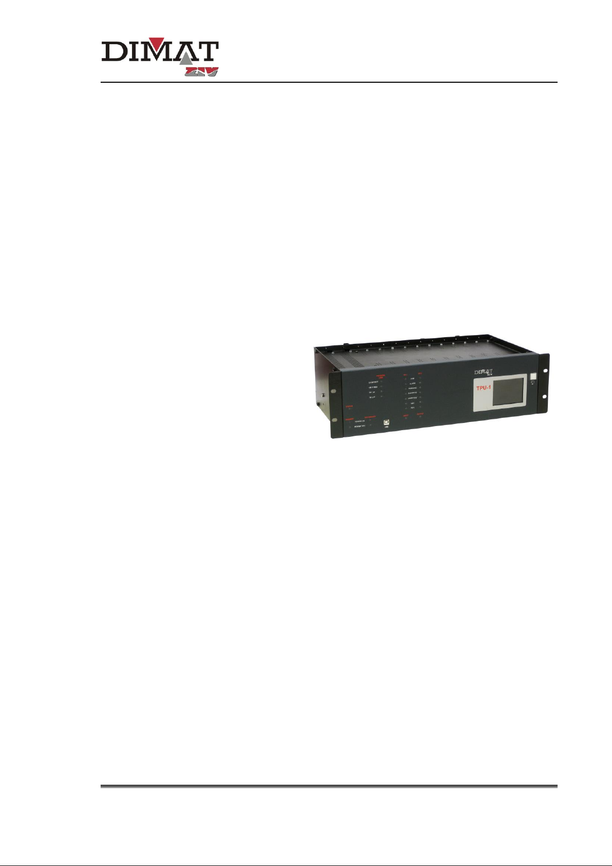
UNIVERSAL TELEPROTECTION
TPU-1
INSTALLATION AND COMMISSIONING MANUAL
Web version TPU-1R
Rev. 5.9 - May 2018
Communication solutions for power utilities
UNIVERSAL TELEPROTECTION TPU-1
INSTALLATION AND COMMISSIONING MANUAL Web version TPU-1R - Rev. 5.9 (May 2018)
2/69
SAFETY SYMBOLS
WARNING OR CAUTION:
This symbol denotes a hazard. Not following the indicated procedure,
operation or alike could mean total or partial breakdown of the
equipment or even injury to the personnel handling it.
NOTE:
Information or important aspects to take into account in a procedure,
operation or alike.

Communication solutions for power utilities
UNIVERSAL TELEPROTECTION TPU-1
INSTALLATION AND COMMISSIONING MANUAL Web version TPU-1R - Rev. 5.9 (May 2018)
3/69
TABLE OF CONTENTS
Page
INTRODUCTION 5
1 MECHANICAL CHARACTERISTICS 6
1.1 SHELF MODULE CAPACITY 7
1.2 REPLACING THE MODULES 8
2 FRONT PLATE ELEMENTS 9
3 INTERNAL SETTINGS 11
3.1 PROCESSING MODULE 11
3.2 PROTECTION-SIDE INTERFACE MODULES
(CIRCUITS FROM ONE TO TWO COMMANDS) 12
3.3 DIGITAL LINE INTERFACE MODULE 14
3.4 DIGITAL SIGNAL I/O INTERFACE MODULE (DSTU) 17
4 CONNECTIONS 18
4.1 POWER SUPPLY 19
4.2 PROCESSING MODULE 20
4.3 LINE INTERFACE MODULES 21
4.3.1 IETU module 21
4.3.2 IDTU module 24
4.3.3 IOTU module 25
4.3.4 IOCT module 26
4.3.5 IPIT module 27
4.3.6 IATU and IBTU modules 28
4.4 PROTECTION-SIDE INTERFACE MODULE
(CIRCUITS FROM ONE TO TWO COMMANDS) 29
4.5 GOOSE PROTECTION INTERFACE MODULE 30
4.6 RELAY INTERFACE MODULES 31
4.7 MODULES FOR TELESIGNALLING AND REMOTE MEASUREMENTS 32

Communication solutions for power utilities
UNIVERSAL TELEPROTECTION TPU-1
INSTALLATION AND COMMISSIONING MANUAL Web version TPU-1R - Rev. 5.9 (May 2018)
4/69
Page
5 COMMISSIONING PROCEDURE 34
5.1 CHECKS 34
5.2 MODULE CONFIGURATION 34
5.3 STARTING UP THE TERMINAL 35
5.4 CONFIGURATION OF THE WEB SERVER 35
5.5 CONFIGURATION OF THE MANAGEMENT COMPUTER 35
5.5.1 Characteristics of the management computer 36
5.5.2 Connections 36
5.5.3 Configuration 39
5.6 STARTING UP THE WEB SERVER 40
5.7 CERTIFICATE OF AUTHENTICITY 42
5.8 LEAVING THE WEB MANAGEMENT 42
5.9 ON-LINE WEB MANAGEMENT AND OFF-LINE WEB MANAGEMENT 42
5.10 UPDATING THE WEB SERVER PAGES 43
6 MAINTENANCE 44
7 TRANSPORT AND STORAGE 47
7.1 TRANSPORT 47
7.2 STORAGE 48
APPENDIX A
IP ADDRESSING 49
APPENDIX B
IEC 61850 STANDARD 52
APPENDIX C
CABINET-MOUNTING TERMINAL BLOCKS 54
APPENDIX D
OPTIONAL LCD DISPLAY 66

Communication solutions for power utilities
UNIVERSAL TELEPROTECTION TPU-1
INSTALLATION AND COMMISSIONING MANUAL Web version TPU-1R - Rev. 5.9 (May 2018)
5/69
INTRODUCTION
This manual describes the installation and commissioning procedure for the TPU-1
universal teleprotection terminal.
Firstly, it indicates the mechanical characteristics of the terminal and how to replace the
modules without damaging either the modules or the terminal. It goes on to describe the
function of the optical indicators on the front plate and shows the position and function of the
internal jumpers that can be configured by the user. It then describes the external
connections of both the power supply and the signals.
Finally, it deals with the commissioning procedure, which begins with a series of checks. It
then describes the connection of the PC followed by how to start up the equipment and the
Management System.
Communication solutions for power utilities
UNIVERSAL TELEPROTECTION TPU-1
INSTALLATION AND COMMISSIONING MANUAL Web version TPU-1R - Rev. 5.9 (May 2018)
6/69
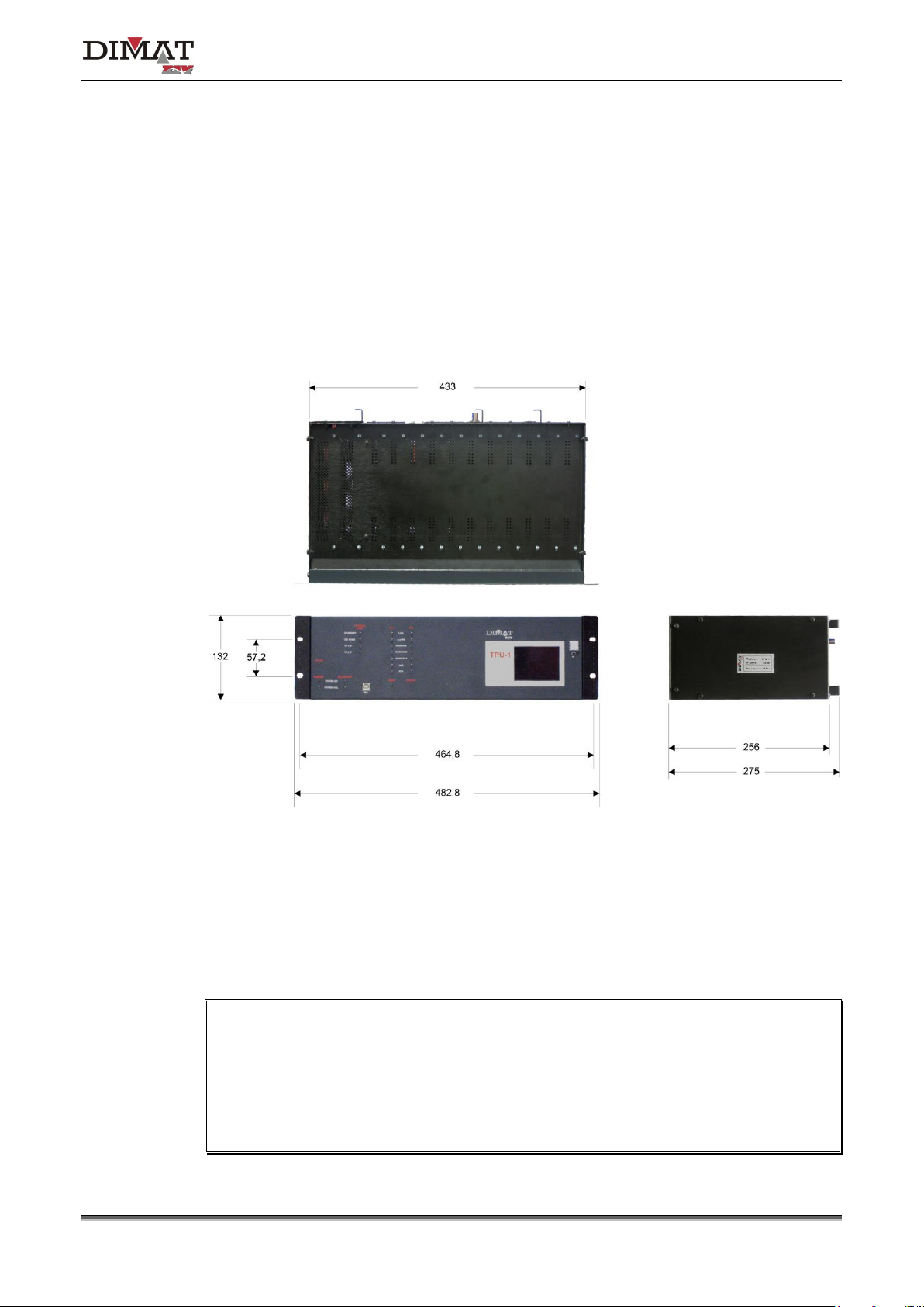
1 MECHANICAL CHARACTERISTICS
The TPU-1 terminal is made up of a 19” shelf that is 3 standard units (s.u.) in height,
prepared for rack mounting.
Figure 1 shows the general dimensions of the shelf as well as the position of the fastening
holes. As can be seen in the figure, the shelf has one ventilation grid.
Figure 1 General dimensions of the TPU-1 shelf
The input and output of signals is carried out by means of the plug-in connectors located at
the rear of the shelf. If one wishes the external connections to be carried out through a
cabinet-mounting terminal block, it can be supplied on request, together with the necessary
cables, see Appendix C.
During installation it must be made sure that the ventilation grid is NOT covered. Once
the shelf has been installed, it must be checked that the ventilation grid on the top is NOT
obstructed in any way.
When installing the terminal in a frame of a cabinet, in order to improve ventilation, a
space equivalent to at least one standard unit must be left above and below it.
Communication solutions for power utilities
UNIVERSAL TELEPROTECTION TPU-1
INSTALLATION AND COMMISSIONING MANUAL Web version TPU-1R - Rev. 5.9 (May 2018)
7/69
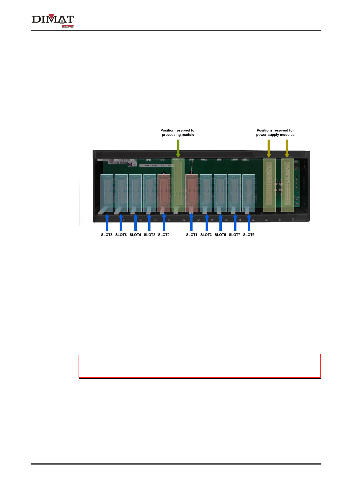
1.1 SHELF MODULE CAPACITY
The shelf can hold up to 13 modules, of which, only that of power supply (or the two
power-supply modules in the case of secondary power-supply) and that of processing have
a fixed position. The rest of the modules (line interface, protection-side interface, relay
interface and those related to the remote measurements application) can be inserted in any
position of the shelf, see Figure 2.
Figure 2 Internal rear view of the TPU-1 shelf
The correspondence between connectors and slots should be taken into account when
establishing the constitution of the equipment, from the Management System, in order to
carry out configuration. It is therefore necessary to indicate the slots one wishes to configure
and the type of module associated with each one, in the corresponding programming page.
The modules are inserted in the shelf with the help of the two handles on the front plate.
The following section describe the procedure for replacing modules.
A module must NOT be replaced whilst the terminal power-supply is connected.
Communication solutions for power utilities
UNIVERSAL TELEPROTECTION TPU-1
INSTALLATION AND COMMISSIONING MANUAL Web version TPU-1R - Rev. 5.9 (May 2018)
8/69
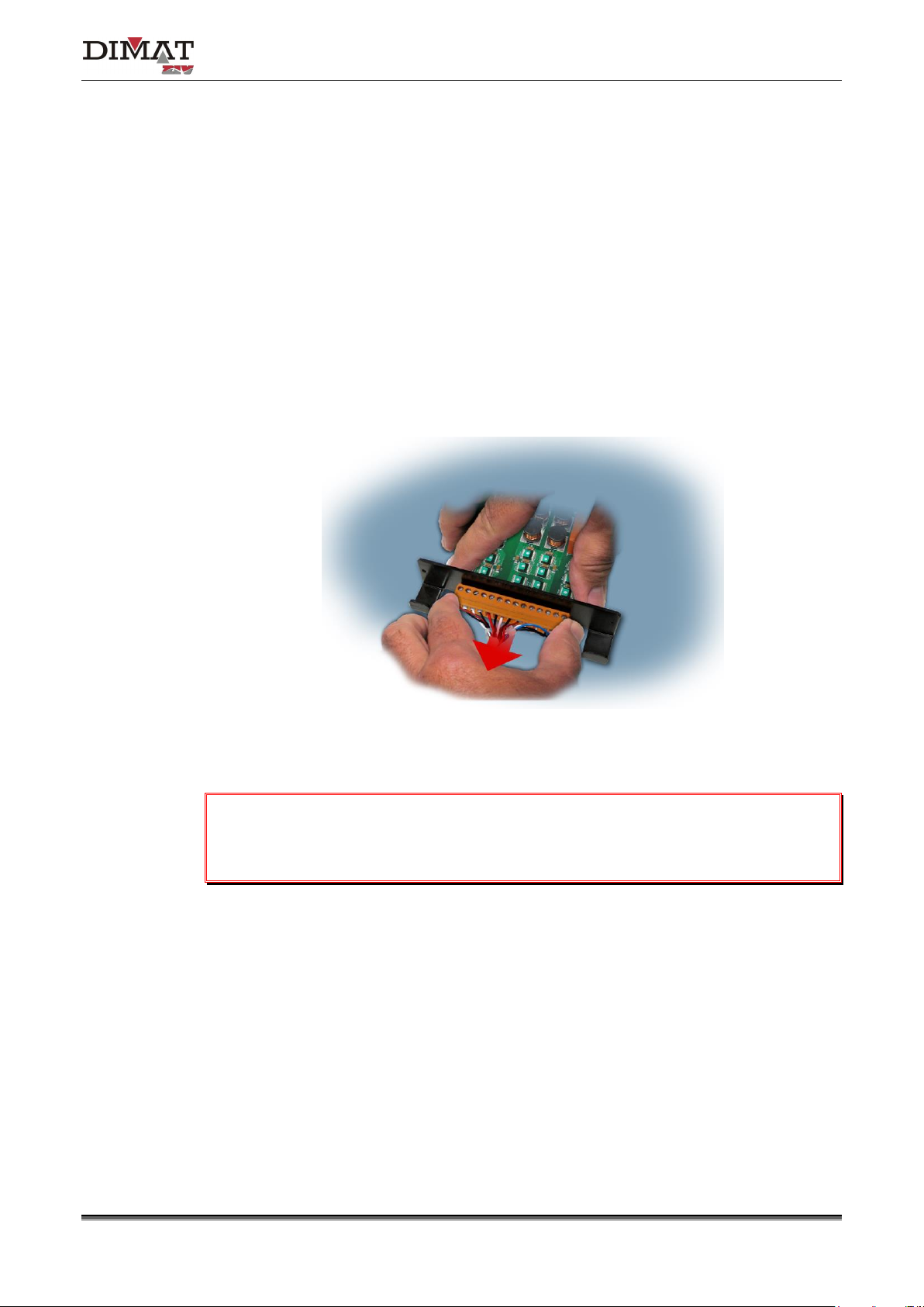
1.2 REPLACING THE MODULES
In order to replace a module in the shelf, the operations indicated below should be carried:
1. Release the two fixing screws of the module.
Depending on the type of module, the earth cable is attached to the upper screw. In that
case, disconnect it.
2. Extract the module by means of the handles.
3. Depending on the type of module, extract the connector.
The earth cable of the module was disconnected in point 1.
Once the module is inserted in the shelf, tighten the module to the chassis and, if
necessary, attach the earth cable to the upper screw.

Communication solutions for power utilities
UNIVERSAL TELEPROTECTION TPU-1
INSTALLATION AND COMMISSIONING MANUAL Web version TPU-1R - Rev. 5.9 (May 2018)
9/69
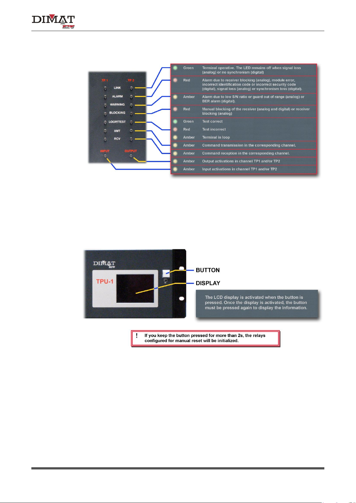
2 FRONT PLATE ELEMENTS
The TPU-1 terminal has twenty-five LEDs on the front plate. The LEDs identified as
PRIMARY and SECONDARY are associated with the terminal power supply. The
PHYSICAL LINK LEDs indicate the interface type being active, and the LEDs identified as
TP 1 and TP2 are associated with the two possible communication channels that can
manage the terminal and to the command transmission and reception circuits.
The front plate also has an USB connector that is for Pweb management
(1)
. It can also have
an optional LCD display which allows certain parameters of the terminal to be monitored,
see Appendix D, without having to access the Management System.
Figure 3 and Figure 4 show the signalling of the different LEDs, and Figure 5 describes the
optional LCD display.
Figure 3 Signalling of LEDs (I)
(1)
Local management system based on a Web interface. The Pweb management, given that it requires a web server external to
the terminal, is known as External Web Management.
Communication solutions for power utilities
UNIVERSAL TELEPROTECTION TPU-1
INSTALLATION AND COMMISSIONING MANUAL Web version TPU-1R - Rev. 5.9 (May 2018)
10/69
Figure 4 Signalling of LEDs (II)
Figure 5 Optional LCD display
Communication solutions for power utilities
UNIVERSAL TELEPROTECTION TPU-1
INSTALLATION AND COMMISSIONING MANUAL Web version TPU-1R - Rev. 5.9 (May 2018)
11/69
3 INTERNAL SETTINGS
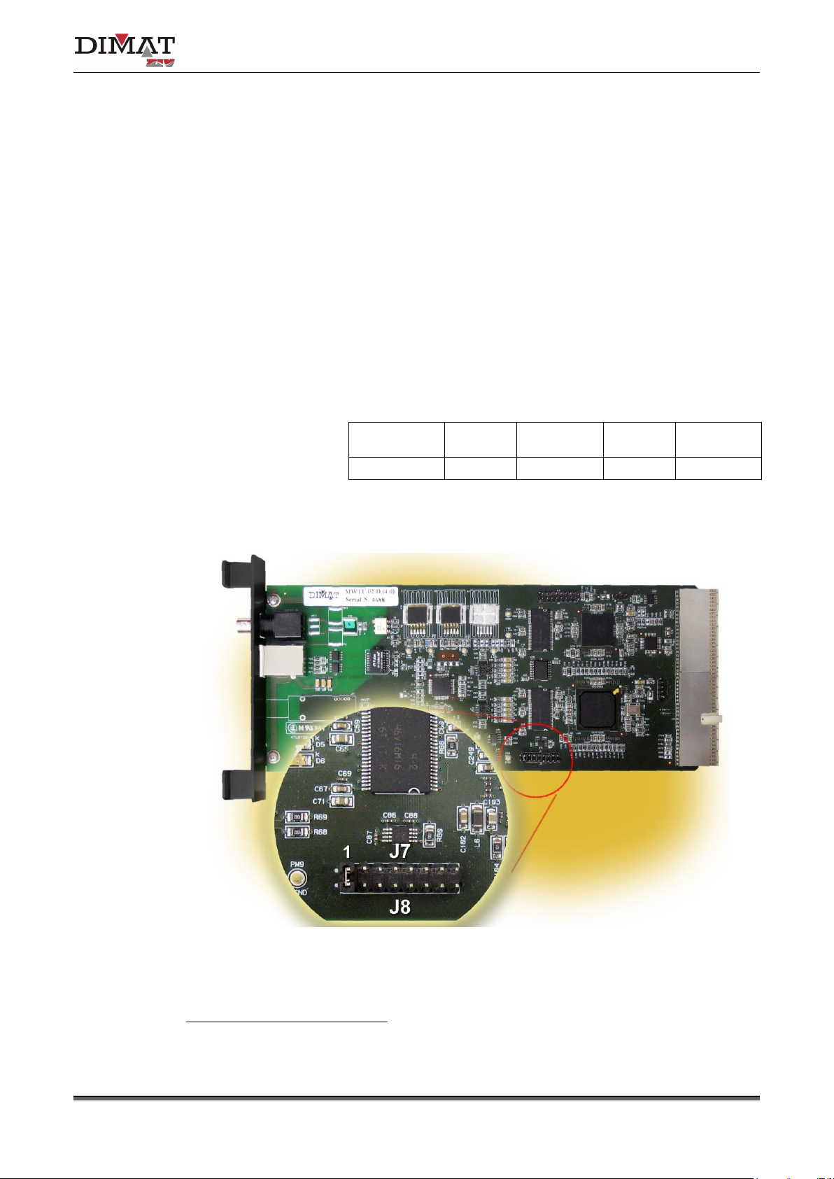
3.1 PROCESSING MODULE
The processing module (MWTU) has configuration elements, the location of which can be
seen in Figure 6.
J7, J8
By carrying out a jumper between pin 1 of J7 and pin 1 of J8, the
IP address by default as well as the default user passwords are
loaded in the terminal, as indicated in Table 1.
Administrator
login
Basic
login
Administrator
password
Basic
password
IP address
(*)
admin
basic
admin
basic
172.16.6.3
Table 1 Default values activated when a jumper between
pin 1 of J7 and pin 1 of J8 is carried out
Figure 6 Location of the configuration elements of the MWTU module
(*)
The IP address in factory is the 172.16.6.3

Communication solutions for power utilities
UNIVERSAL TELEPROTECTION TPU-1
INSTALLATION AND COMMISSIONING MANUAL Web version TPU-1R - Rev. 5.9 (May 2018)
12/69
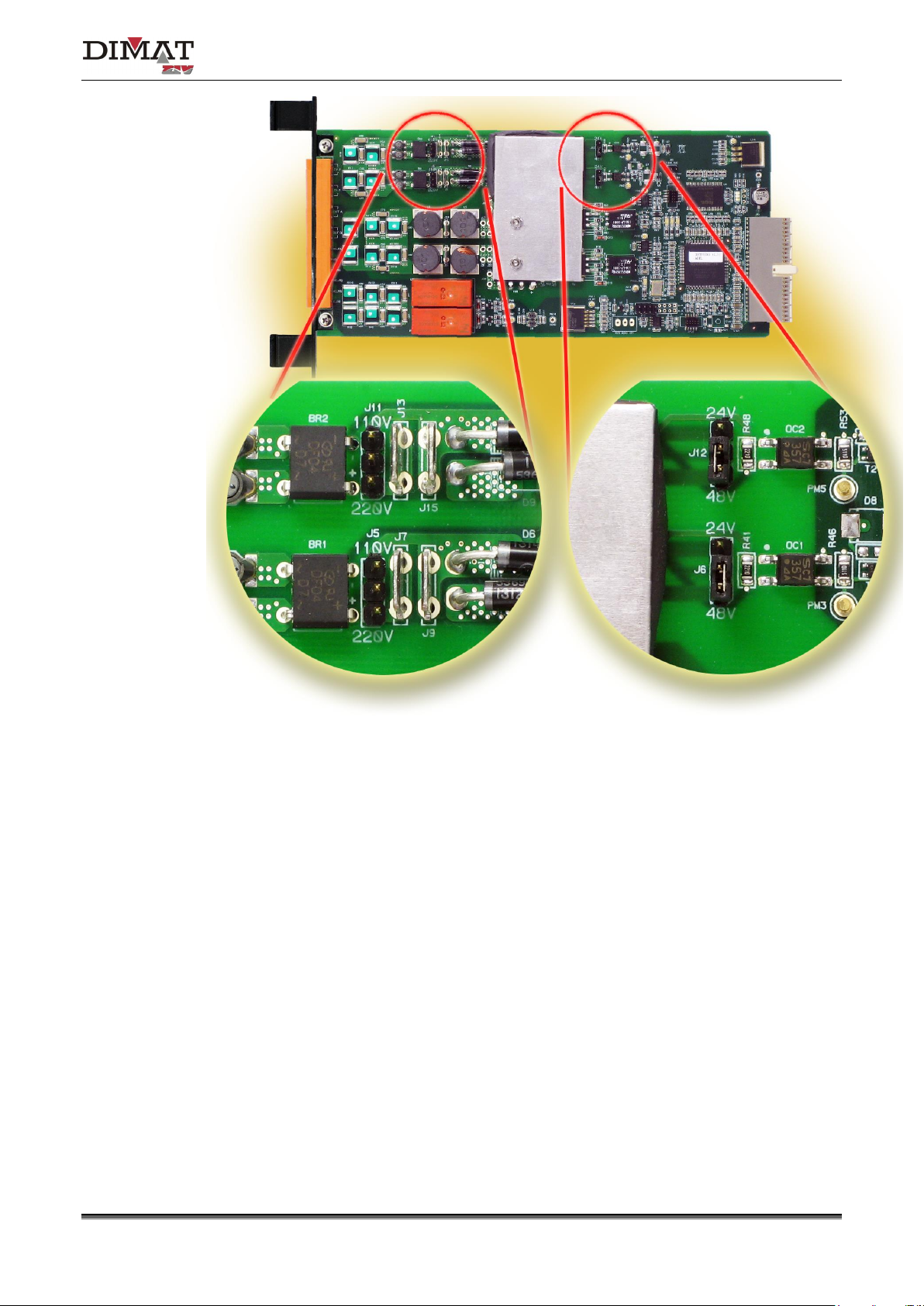
3.2 PROTECTION-SIDE INTERFACE MODULES
(CIRCUITS FROM ONE TO TWO COMMANDS)
Each protection-side interface module (IPTU) has two independent input circuits whose
activation can be established, by means of jumpers, for a nominal voltage of 24, 48, 110 or
220 VDC.
Once the nominal voltage has been established, the minimum voltage that guarantees
the input activation is 19 VDC for 24 VDC, 38 VDC for 48 VDC, 88 VDC for 110 VDC and
176 VDC for 220 VDC, and the maximum voltage that guarantees NON input activation is
14 VDC for 24 VDC, 29 VDC for 48 VDC, 66 VDC for 110 VDC and 132 VDC for 220 V
DC.
Figure 7 shows the position of the input-activation nominal-voltage configuration jumpers in
the IPTU module.
Under NO circumstances must the maximum operating voltage be exceeded, being:
29 VDC for 24 VDC, 58 VDC for 48 VDC, 132 VDC for 110 VDC and 264 VDC for 220 VDC.
a) Model A
Communication solutions for power utilities
UNIVERSAL TELEPROTECTION TPU-1
INSTALLATION AND COMMISSIONING MANUAL Web version TPU-1R - Rev. 5.9 (May 2018)
13/69
b) Model B
Figure 7 Input-activation nominal-voltage configuration jumpers
of the IPTU module

Communication solutions for power utilities
UNIVERSAL TELEPROTECTION TPU-1
INSTALLATION AND COMMISSIONING MANUAL Web version TPU-1R - Rev. 5.9 (May 2018)
14/69
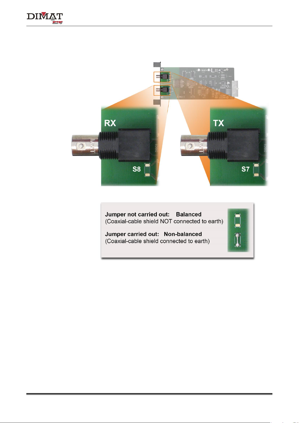
3.3 DIGITAL LINE INTERFACE MODULE
As can be seen in Figure 8, the IDTU.00 modules of version lower than 3.0 have two
jumpers, prepared for soldering, identified as S7 and S8, which must be carried out if one
wishes to connect the transmission and reception cable shields to earth, respectively. If the
jumper is not carried out, it is a floating shield.
The standard recommends to connect both shields to earth. Jumpers S7 and S8 are carried
out at the factory, which corresponds to the shield connected to earth.
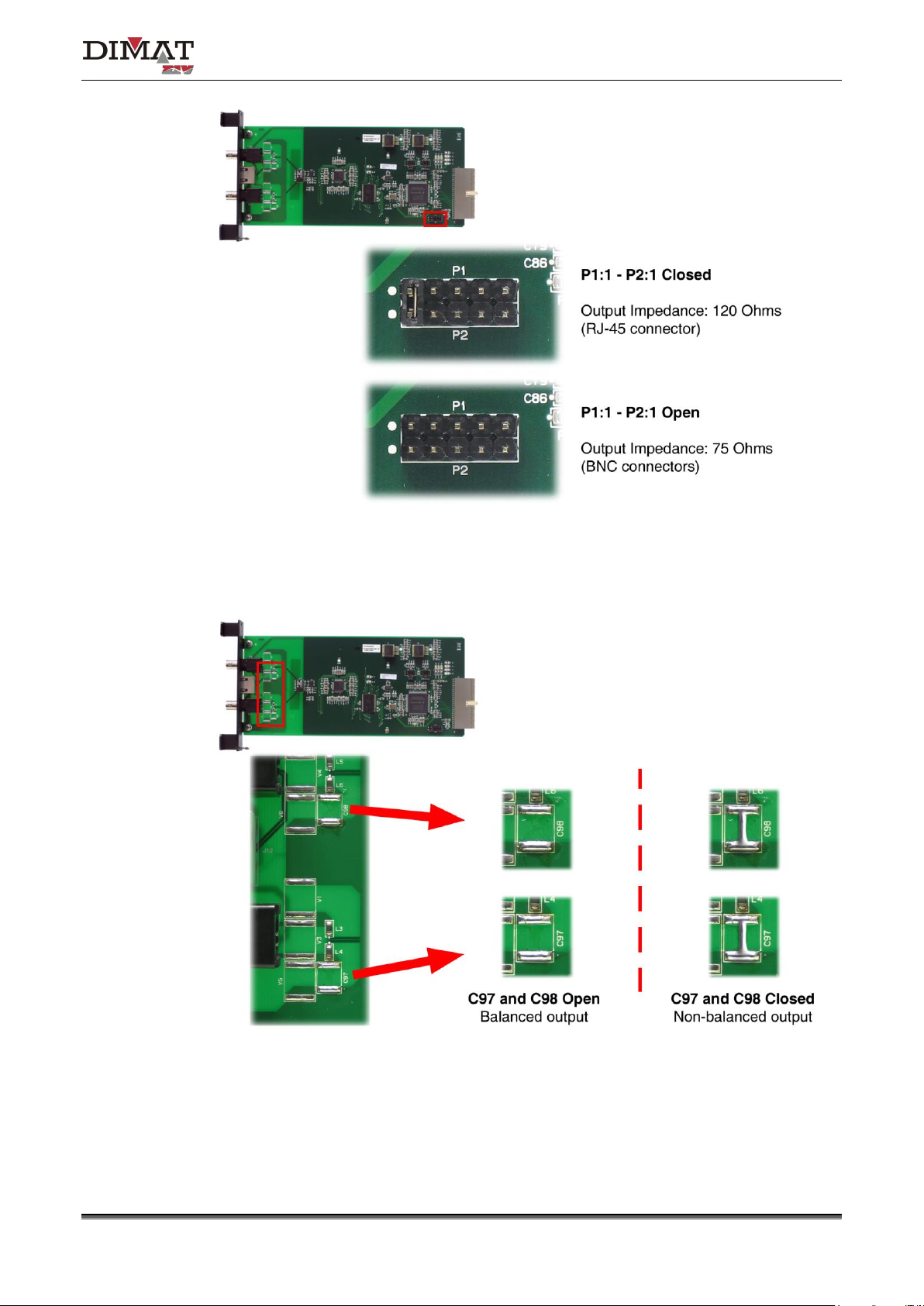
As can be seen in Figure 9, the IDTU.00 modules of version 3.0 have the P1-P2 setting and
two jumpers prepared for soldering, identified as C97 and C98.
The P1-P2 setting allows the selection of the output impedance according to the type of
connector:
- P1:1 and P2:1 closed: 120 Ω (RJ-45).
- P1:1 and P2:1 open: 75 Ω (BNC).
In IDTU.00 modules of version 3.1, the type of connector (BNC or RJ-45) is programmed
from the TPU-1 Management System.
The solder jumpers C97 and C98 determine whether the cable shield is connected to earth
or not:
- C97 and C98 open: Balanced (cable shield NOT connected to earth). This
configuration is normally used for the RJ-45 (120 Ω) connector.
- C97 and C98 closed: Non-balanced (cable shield connected to earth). This
configuration is normally used for the BNC (75 Ω) connectors.
Communication solutions for power utilities
UNIVERSAL TELEPROTECTION TPU-1
INSTALLATION AND COMMISSIONING MANUAL Web version TPU-1R - Rev. 5.9 (May 2018)
15/69
Figure 8 Location of jumpers S7 and S8, prepared for soldering, of the
IDTU.00 module of version lower than 3.0
Communication solutions for power utilities
UNIVERSAL TELEPROTECTION TPU-1
INSTALLATION AND COMMISSIONING MANUAL Web version TPU-1R - Rev. 5.9 (May 2018)
16/69
a) Location of P1-P2 setting
b) Location of C97 and C98 solder jumpers
Figure 9 Location of settings in the IDTU.00 module of version 3.0
Communication solutions for power utilities
UNIVERSAL TELEPROTECTION TPU-1
INSTALLATION AND COMMISSIONING MANUAL Web version TPU-1R - Rev. 5.9 (May 2018)
17/69
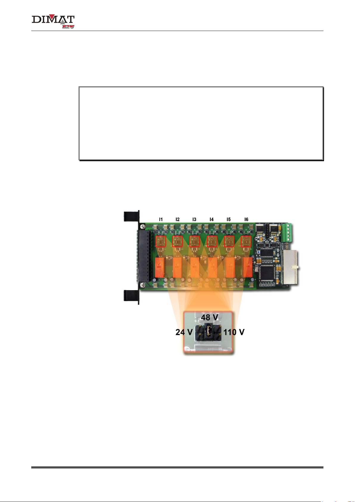
3.4 DIGITAL SIGNAL I/O INTERFACE MODULE (DSTU)
The digital signal I/O interface module (DSTU) has six digital optocoupled inputs whose
activation can be established, by means of jumpers, for a nominal voltage of 24, 48 or
110 VDC.
Once the nominal voltage has been established, the minimum voltage that guarantees
the input activation is 19 VDC for 24 VDC, 38 VDC for 48 VDC and 100 VDC for 110 VDC, and
the maximum activation voltage, which must under NO circumstances be exceeded, is
28 VDC for 24 VDC, 57 VDC for 48 VDC and 150 VDC for 110 V
DC.
The minimum voltage that guarantees NON activation is 10 VDC for 24 VDC, 19 VDC for
48 VDC and 50 VDC for 110 V
DC.
Figure 10 shows the position of the input-activation nominal-voltage configuration jumpers in
the DSTU module.
Figure 10 Input-activation nominal-voltage configuration jumpers
of the DSTU module
Communication solutions for power utilities
UNIVERSAL TELEPROTECTION TPU-1
INSTALLATION AND COMMISSIONING MANUAL Web version TPU-1R - Rev. 5.9 (May 2018)
18/69
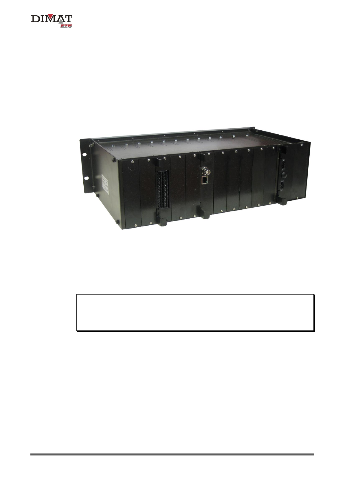
4 CONNECTIONS
This section describes the connectors and terminals associated with each module for
external connections. If one wishes the external connections to be carried out through a
cabinet-mounting terminal block, it can be supplied on request, together with the necessary
cables see Appendix C.
Figure 11 Rear view of the TPU-1 shelf
In disturbed environments, it is recommended to use screened cables for the
connections. For safety reasons the screen of the connection cables must be grounded,
the connection to earth being made at just one end to avoid interference.
Communication solutions for power utilities
UNIVERSAL TELEPROTECTION TPU-1
INSTALLATION AND COMMISSIONING MANUAL Web version TPU-1R - Rev. 5.9 (May 2018)
19/69
4.1 POWER SUPPLY
As seen from the rear, the position most to the right corresponds to the main power-supply
module type ATPU. If redundancy is used, the secondary power supply is located next to
the main power-supply module.
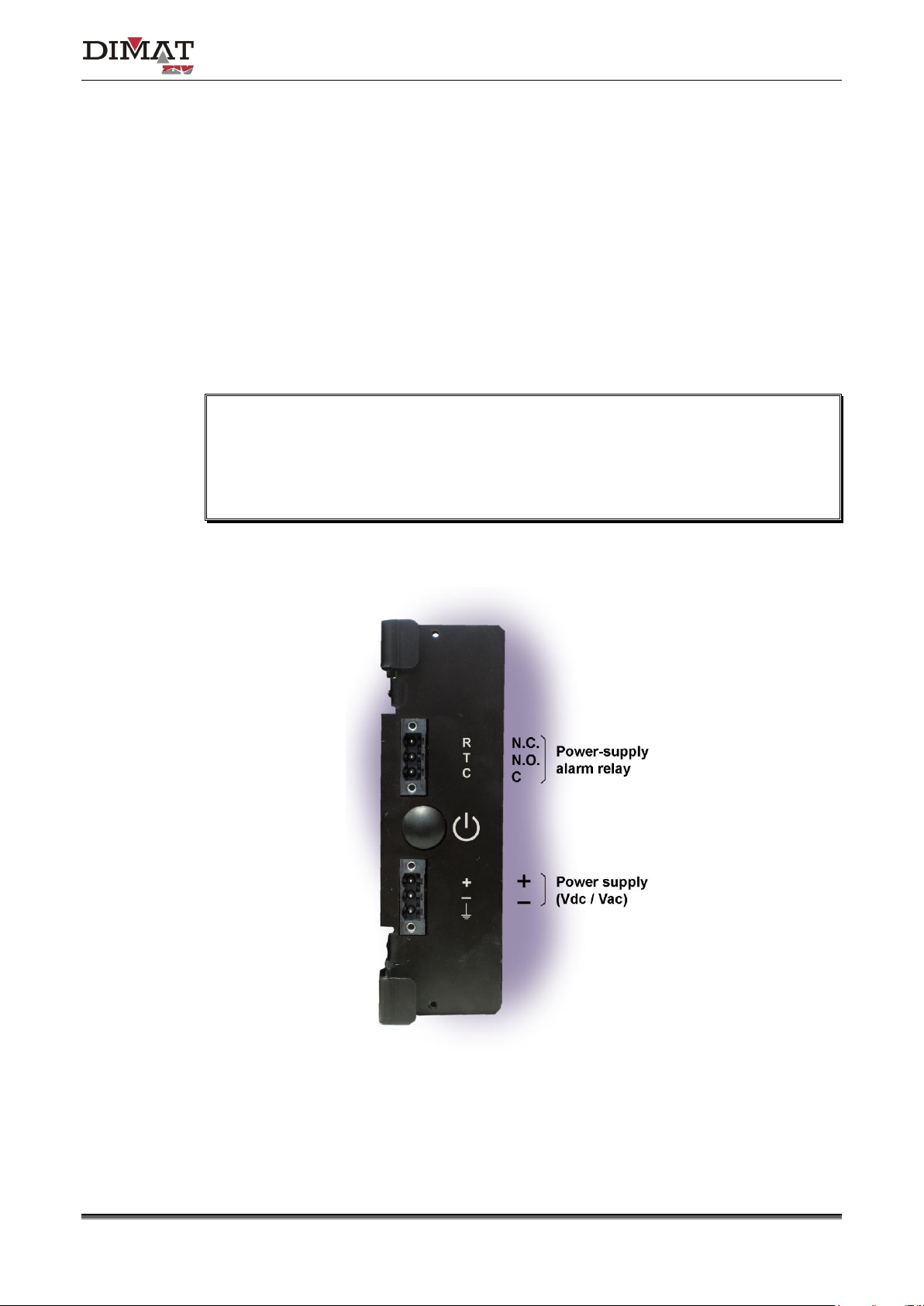
Figure 12 shows a front view of the ATPU power-supply module. As can be seen, the
power-supply module has two terminal blocks on the front plate. One is associated with the
power supply and the other to the power-supply alarm relay.
In normal operation conditions the alarm relay is energized, that is to say, the N.O. and C
contacts are short-circuited. Should a failure occur in the power supply, not only does the
LED POWER FAIL on the front plate light up but the N.C. and C contacts of the alarm
relay are also short-circuited.
Figure 12 ATPU power-supply module
Communication solutions for power utilities
UNIVERSAL TELEPROTECTION TPU-1
INSTALLATION AND COMMISSIONING MANUAL Web version TPU-1R - Rev. 5.9 (May 2018)
20/69
4.2 PROCESSING MODULE
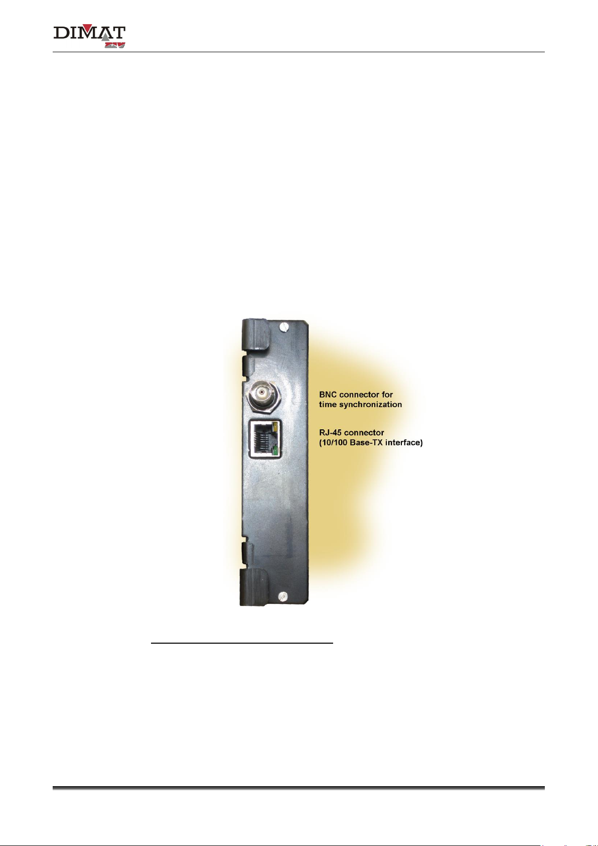
Figure 13 shows a front view of the MWTU module. As can be seen in the figure, there are
two connectors on the front plate, one for the 10/100 Base-Tx or 100Base-Fx interface and
the other one for connection to a GPS synchronized time equipment.
The BNC connector allows the TPU-1 terminal to synchronize its internal real time clock with
the time reference given by any GPS synchronized time equipment that has an IRIG-B
standard output.
The operation of the RJ-45 (10/100Base-Tx interface) or MT-RJ (100Base-Fx interface)
connector must be established from the Management System.
Make sure that the module is completely fixed to the chassis.
LEDs associated with the RJ-45 connector
• Amber. It stays on when the link is established correctly.
• Green. It flashes in the case of activity in the interface.
Figure 13 MWTU processing module connector
Communication solutions for power utilities
UNIVERSAL TELEPROTECTION TPU-1
INSTALLATION AND COMMISSIONING MANUAL Web version TPU-1R - Rev. 5.9 (May 2018)
21/69
4.3 LINE INTERFACE MODULES
The TPU-1 terminal has one or two line interface modules, depending on whether it
manages one or two communication channels.
The line interface modules are divided into analog and digital line interface modules.
The digital line interface modules available are: IETU, IDTU, IOTU, IOCT and IPIT. The
analog line interface modules available are: IATU and IBTU.
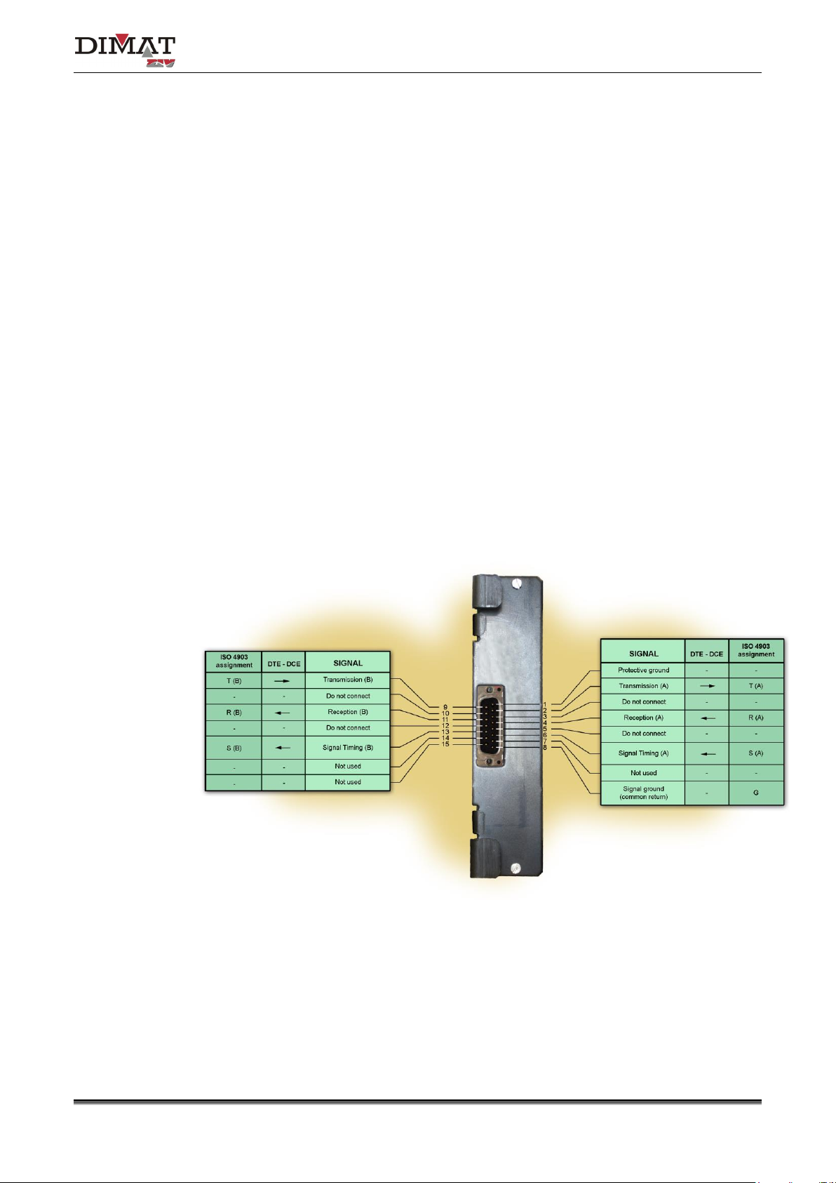
4.3.1 IETU module
The IETU module gives a 64 kbit/s interface that can be programmed according to
Recommendations X.21/V.11, V.35 or G.703 of the ITU-T.
The IETU module has a 15-pin SUB-D connector on the front plate. Figure 14 to Figure 18
show the assignment of the contacts of the connector for the V.11, X.21, V.35, G.703
codirectional and G.703 contradirectional interfaces, respectively.
Figure 14 Use of the connector of the IETU module for V.11 interface
 Loading...