

Page 1
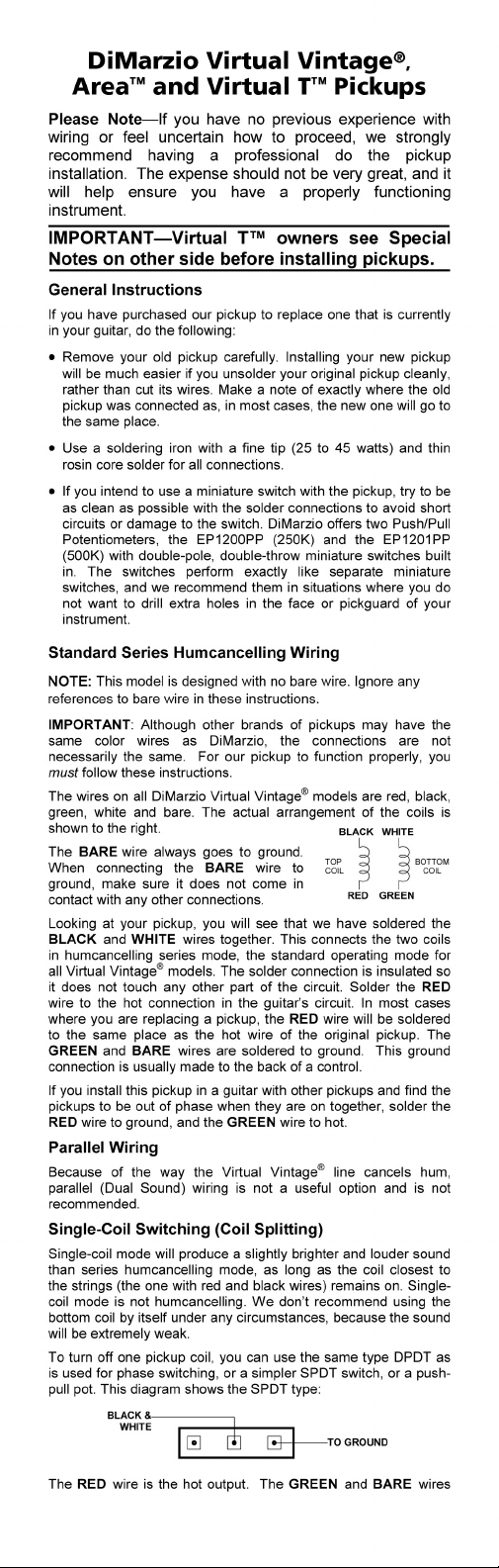
Page 2
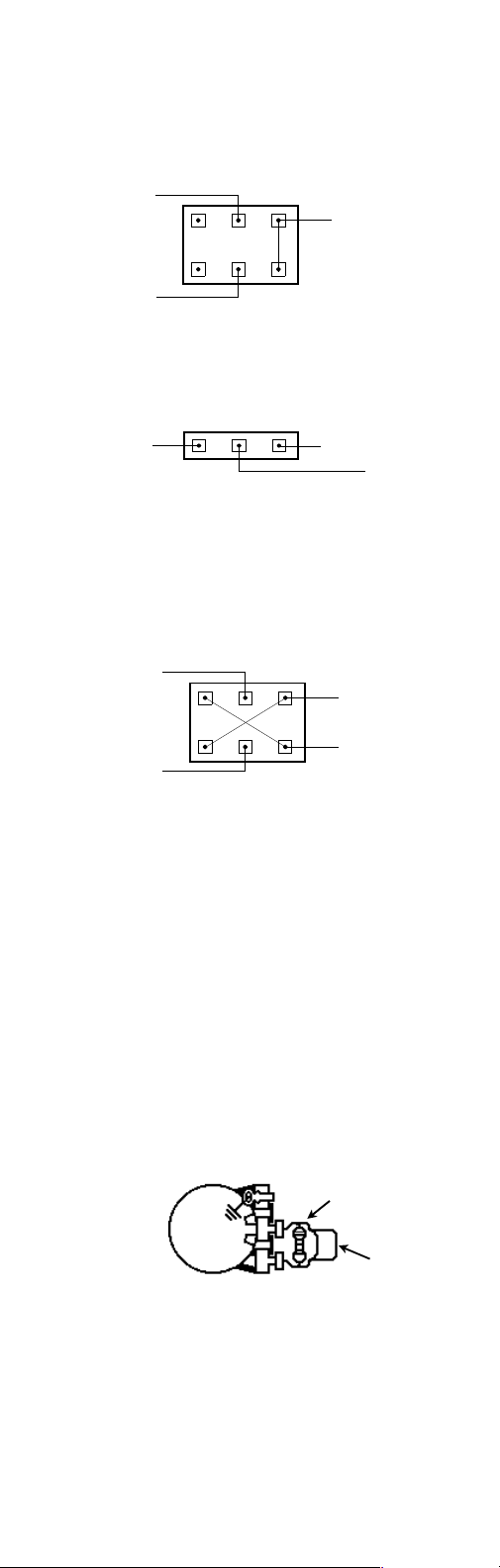
are soldered to ground. Carefully rem ove the insulation from the
black/white connection and solder a single wire to the connection.
This will be the coil-split wire, which will connect to the split
switch. Be sure to insulate this connection. As only one side of
the DPDT mini-switch is used, you may choose to have two
pickups go from double- to single-coil on one switch, like this:
BLACK &
WHITE
TO GROUND
BLACK &
WHITE
Again, the GREEN and BARE wires from both pickups go to
ground. The RED wires on both pickup are the hot outputs.
To wire a split switch to a reverse-phase Virtual Vintage
®
using a
SPDT switch (or one side of a DPDT switch), solder the RED and
BARE wires to ground and wire the switch like this:
BLACK & WHITE
GREEN
HOT OUTPUT
TO PICKUP
SELECTOR
Phase Switch
Phase switching can only function in an instrument with two or
more pickups. The effect will only occur when both pickups are
on, and will be most obvious when the pickups are at
approximately the same volume. Only one of the pickups should
be wired to the phase switch, and it makes no audible difference
which pickup you choose. The switch is a double-pole, doublethrow type: DPDT (DiMarzio catalog number EP1106) or pushpull pot (EP1200PP or EP1201PP):
RED
HOT OUTPUT
GREEN
Component Values
®
The Virtual Vintage
2.1, 2.2, all VirtuAL 2™ models and Virtual
GROUND OUTPUT
Tä were designed to work with 250K controls. For a brighter
overall sound, try 500K or 1 Meg tone controls (EP1202).
For all other Virtual Vintage
®
models we recommend 500K ohm
(EP1201) pots for volume and tone. For more highs and overall
‘cut’, try a 500K volume with a 1 Meg tone pot. If you’re mixing
VirtuAL 2ä and Virtual Vintage
®
models, it’s usually best to use
the higher resistance control value. For the tone controls, we
recommend a capacitor value of .022 µfd or .033 µfd. The .033
value will roll off more high frequencies than the .022.
Treble Compensation
Many players notice a loss of high frequencies when the volume
control is turned down. To avoid this, install a 560 pF capacitor
alone or with a 300K ohm resistor (270K or 330K will also work)
in parallel across the two “hot” legs of the volume control, as
shown in the drawing. Try to solder these components cleanly to
the legs of the volume control, without breaking the solder
connections that are already present.
Height Adjustment
Height adjustment is very much a matter of personal taste, and
the following distances should only be taken as recommended
starting points.
The Virtual Vintage
have low magnet pull, and can be adjusted relatively close to the
strings. At the highest fret (usually the 21
recommended distances from the top of the magnet to the bottom
of the string are: neck and middle pickups low E 3/32” (2.4 mm),
high E 1/16” (1.6 mm), bridge pickup low E 1/16” (1.6 mm), high
E 3/64” (1.2 mm). These settings will provide a lot of presence
and attack. For a more open 1950s sound, try adjusting the
RESISTOR
CAPACITOR
®
2.1, 2.2, Virtual T™ and VirtuAL 2™ models
st
or 22nd), the closest
Page 3

pickups 1/32” (0.8 mm) further from the strings.
All other Virtual Vintage
®
models use alnico 5 magnets with
higher magnet pull. The closest recommended distances are:
neck and middle pickups low E 1/8” (3.2 mm), high E 3/32” (2.4
mm), bridge pickup l ow E 3/32” (2.4 mm), high E 1/16” (1.6 mm).
Special Note for Virtual T™ Bridge Model
®
Some older Telecaster
guitars and vintage reissues do not
ground the bridge assembl y with a wire. The grounding was
accomplished via a metal plate on the bottom of many Tele
bridge pickups. The Virtual T™ does not do this, but it is still
important that the bridge be grounded to eliminate noise. If there
is no independent ground wire running from the underside of the
bridge to the control assembly, you should run an insulated wire
from the back of the volume control through the bridge pickup
cable exit and strip 1-2 inches (3-5 cm) of insulation from the
end. Place the bare portion of the wire between the bridge and
the face of the guitar so it is held securely when the bridge is
screwed back to the guitar body after the new pickup is installed.
Special Note for Virtual T™ Neck Model
The mounting dimensions of this model are based on U.S.-made
Fender Telecasters
have a slot for the neck pickup that is too narrow to fit this pickup.
The recommended width for the pickguard slot is .610” (15.5
mm). If the slot is too narrow, it should be widened with
sandpaper or a file prior to pickup installation. Do not force the
pickup through the slot if the slot is too narrow.
We have included two sets of mounting screws. The wood
screws are for use with a pickup directly mounted to the body.
Machine screws are for mounting through a pickguard.
®
. Some pickguards from other sources may
Additional Notes
Wiring diagrams and technical information may be found on our
website: http://www.dimarzio.com
All DiMarzio pickups have been potted in an exclusive
penetrating formula to eliminate squeal and subdue extraneous
noise. For further noise reduction, we recommend shielding the
entire guitar internally with DiMarzio Shielding Tape (EP1000).
This will eliminate stray hum fields from the circuitry of your
guitar.
If you have any problems or questions, please call our tech line,
(718) 816-8112 between 12:00 PM and 5:00 P M Eastern Time or
email [email protected].
Ò
and TelecasterÒ are registered trademarks of Fender
Fender
Musical Instrument Corp., with which DiMarzio, Inc. is not
affiliated.
1388 Richmond Terrace
P.O. Box 100387
Staten Island, NY 10310 USA
Tel (718) 981-9286 Tech (718) 816-8112
Fax (718) 720-5296
Email: [email protected]
 Loading...