

Page 1
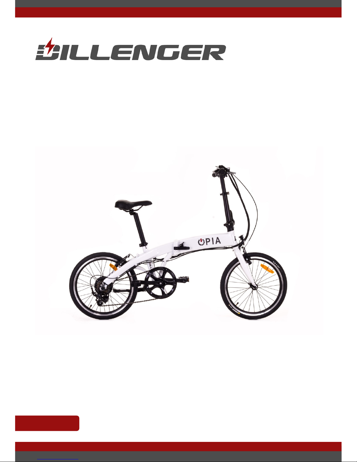
USER MANUAL OPIA
LAST UPDATED: 2/12/2016 1
OPIA
USER MANUAL
This manual is a guide on how to complete assembly, operate, maintain
and troubleshoot your electric bike.
ENGLISH
Page 2

USER MANUAL OPIA
LAST UPDATED: 2/12/2016 2
Dillenger would like to thank you for support us with your purchase. We hope that
you will continue to support us into the future, to help us bring the best and most
affordable products to the market, without sacricing quality.
If you have any questions about your product that isn't covered in this manual,
please get in contact with your local Dillenger dealership or the us at Dillenger
directly.
We hope that our product serves your needs and ideas well into the future. Thank
you for reading.
Before your ride we recommend that you check over the bike with a set of tools.
Though this is completed by Dillenger dealers before dispatch and sale, though
we still recommend this to be completed regularly to ensure the safe and smooth
operation of your electric bike.
MECHANICAL SAFETY CHECK
Before undertaking your rst ride, we recommend that you familiarise yourself
with the controls and performance before operation. Ensure that there is also
adequate space in front of you before starting your rst ride. Completing these
few things will ensure that your rst ride is a safe one. Remember to wear a
helmet at all times while operating the electric bicycle.
FIRST RIDE CHECK
THANK YOU!
Page 3

USER MANUAL OPIA
LAST UPDATED: 2/12/2016 3
TABLE OF CONTENTS
EBike Components and Terminology ....................................................... 4
Assembly .............................................................................................. 6
Unboxing ........................................................................................ 6
Inventory ........................................................................................ 7
Front Wheel .................................................................................... 8
Front Brakes ................................................................................... 9
Handlebar Assembly ..................................................................... 10
Pedals .......................................................................................... 12
Seat ............................................................................................. 12
Additional checks ......................................................................... 13
Operation ............................................................................................ 14
Battery Charging ........................................................................... 14
Battery Removal ............................................................................ 15
Handlebar Display Operation ......................................................... 16
Folding ......................................................................................... 17
Battery Information .............................................................................. 20
Maintenance ....................................................................................... 23
Troubleshooting Tips ........................................................................... 24
Troubleshooting Table ......................................................................... 25
Contact Us .......................................................................................... 26
Page 4
USER MANUAL OPIA
LAST UPDATED: 2/12/2016 4
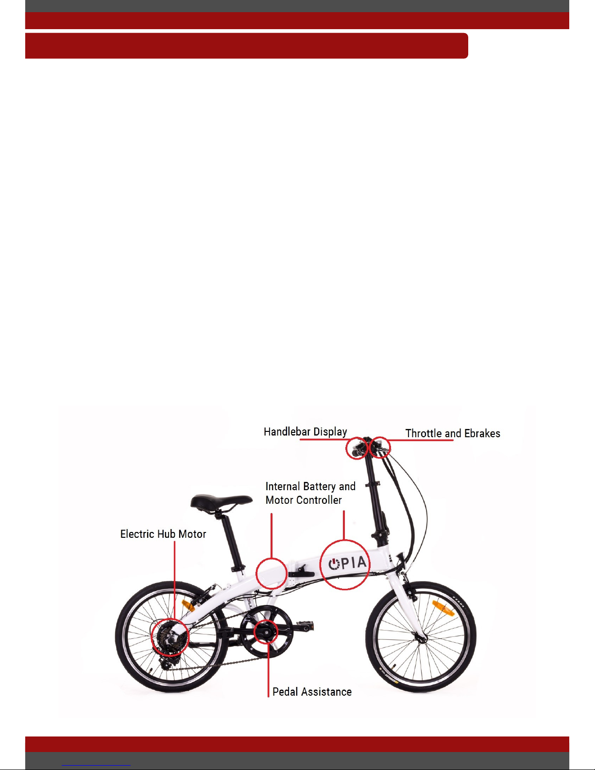
This section will help you understand the operation of an electric bicycle and the
common terms and components involved. If you are familiar with what an electric
bike is and how it operates, then feel free to skip over this section.
An electric bike consists of multiple complex electronic components that are
powered from a central location, the battery. The most common components of
an electric bike are:
A) Electric Motor
B) Motor Controller
C) Battery
D) LCD/Handlebar Display
E) Throttle (Optional)
F) Pedal Assistance Sensor and Magnet Ring
G) Electric Brake Cut-offs (E-brake cut-offs)
EBIKE COMPONENTS AND TERMINOLOGY
Page 5

USER MANUAL OPIA
LAST UPDATED: 2/12/2016 5
A) Electric Motor
The muscle of the electric bike, this component is what applies the rotational
force to the wheels and propels the bicycle forward. In most cases these motors
are a hub type motor meaning that the motor is built onto the wheel or axle. Some
motors will be located near the bicycle pedals and are called mid-drive or crank
drive motors.
B) Motor Controller
The main brain of the electric bike. This device takes in inputs from other
components and operates the motor. A very complex piece of electronics. This is
generally built into the frame of the electric bicycle somewhere, though can be
found attached to the motor or frame of the bicycle.
C) Battery
The heart of the electric bike. Without this electronic component there will be no
speedy take offs and smooth runs over hills. The battery of an electric bike is
generally a Lithium Ion type (though some are still lead acid). They have battery
management systems that ensure the safe operation and charging of the battery.
D) LCD/Handlebar Display
The second brain of the electric bike. This component takes in input from the rider
and provides it to the motor controller. Or uses the information to restrict the
motor controllers operation. This device usually allows the rider to change pedal
assistance levels, check battery levels and provide other functions/displays.
E) Throttle (Optional)
This device is controlled by the rider usually located on the handlebar. If the rider
operates this device the motor controller will detect its operation and propel the
bike based on the amount of throttle utilised.
F) Pedal Assistance Sensor and Magnet Ring
This device is another input to the motor controller. It will detect the rotation of
the pedals and tell the motor controller of this. The motor controller will then
activate power to the motor based on the setting on the LCD/handlebar display.
G) Electric Brake Cut-offs (E-brake cut-offs)
This component is either attached to the brakes or built in to the brakes. It detects
the actuation of the brakes and cuts the motor off. This is an added safety feature
built into most pedal assistance based electric bikes.
Page 6

USER MANUAL OPIA
LAST UPDATED: 2/12/2016 6
This section will help complete the initial installation of the electric bike. This is
generally only required if you purchased the bicycle online away from our retail
stores. Though the information in this section can be helpful for new users.
ASSEMBLY
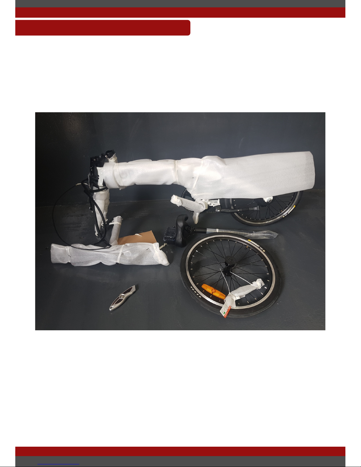
Unboxing your new electric bike can be an exciting prospect. Though we
recommend caution while unpacking the bike. It can be easy to get a bit
enthusiastic and accidently scratch the side of you bike with a cardboard knife or
pair scissors.
It is recommend that you have a partner for this section as removing the electric
bike by ones self can be a difcult process as they can be quite heavy. With two
people you should be able to easily lift the bicycle out of the box that it is received
in.
Carefully unwrap your electric by bike removing all packaging foam and wrapping
from each section of the bicycle frame. As mentioned above carefully utilise tools
such as knifes and snips to remove the packaging as it can be easy to mark the
paint work in this situation.
ASSEMBLY—UNBOXING
Page 7
USER MANUAL OPIA
LAST UPDATED: 2/12/2016 7
You should now have all of the following items in front of you, ready for
installation.
ASSEMBLY—INVENTORY
Page 8
USER MANUAL OPIA
LAST UPDATED: 2/12/2016 8
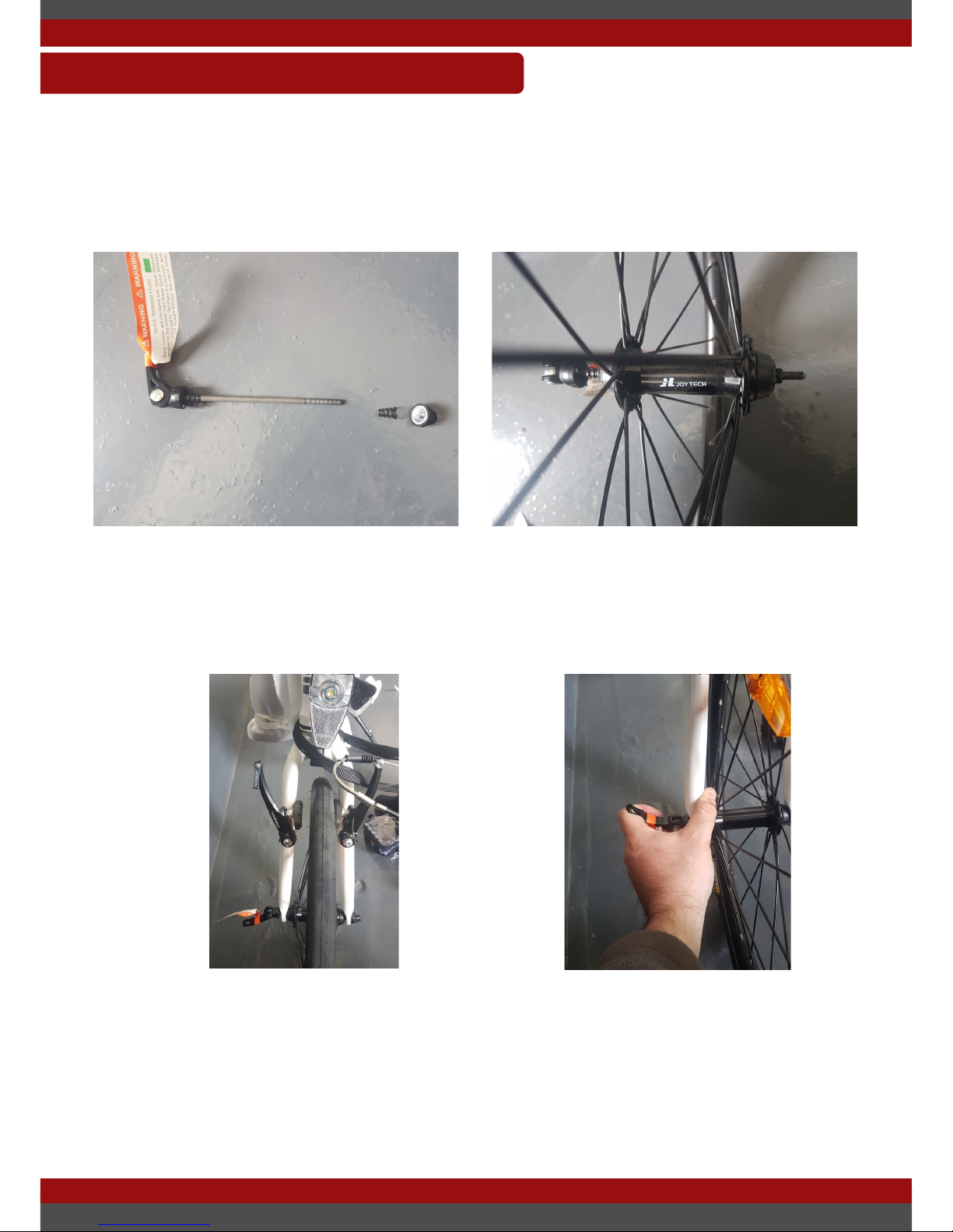
Installation of the front wheel is made simple with the quick release axle. The
quick release axle is zip tied to the spokes of your front where. Remove the zip
ties and unscrew the nut off the axle as shown in the top left picture.
ASSEMBLY—FRONT WHEEL
Insert the axle through the front wheels hub and loosely screw on the nut. Ensure
that you insert the spring on before the nut. You can now place the front wheel in
the front forks of the bike. Insert the wheel as shown below. Tighten the quick
release mechanism by tightening the nut on the axle.
Close the axle clamp to lock the wheel on the bike. If this is quite easy to do you
may need to tighten the nut a little more until it is rm clamp.
Page 9
USER MANUAL OPIA
LAST UPDATED: 2/12/2016 9
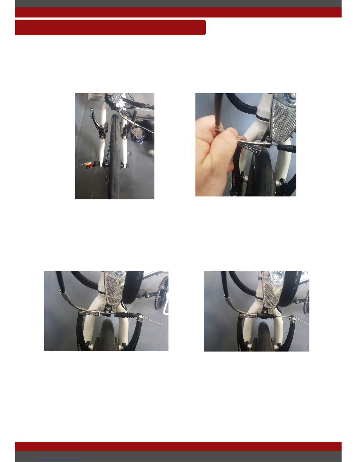
To install the front wheel it is likely that the front brakes will not be attached. This
section will give you a basic step by step of how to reattach the brakes.
ASSEMBLY—FRONT BRAKES
Locate the front brakes. One side of the brakes will have a clip insert to hold the
cable line. Simply reinsert the cable line into the clip as shown in the pictures.
Your brakes may need adjustment now to properly align them to the rim of the
wheel. You can do this with a 5mm allen key. On each brake pad is a bolt that
when loosen will allow you to reposition the brake pads into a more suitable
location. Ideally each brake pad will have a small gap between it and the rim of
the wheel.
Page 10
USER MANUAL OPIA
LAST UPDATED: 2/12/2016 10
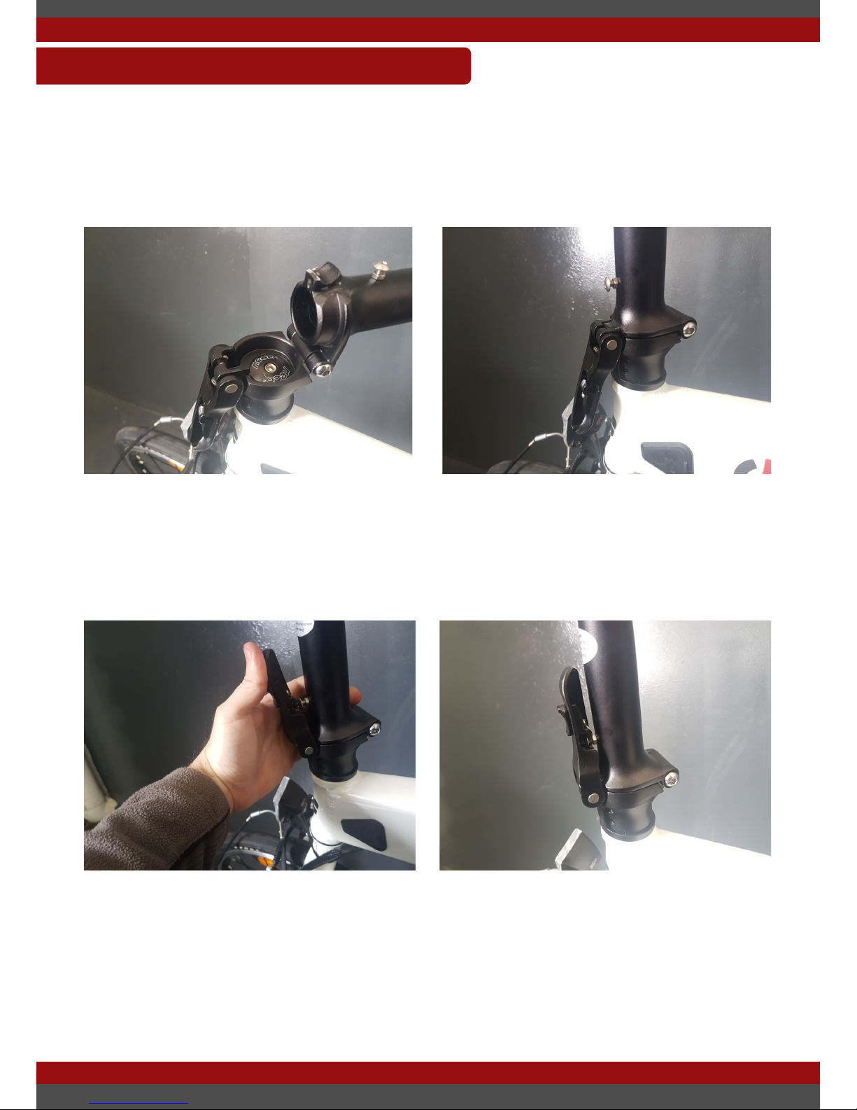
Installation of the handlebars is a simple process. Just follow the following steps.
ASSEMBLY—HANDLEBARS
Locate the handlebar folding joint, this can be seen in the top left picture. Rotate
this upwards to close the folding joint. Please note also that the allen bolt shown
in the top left picture will adjust the steering alignment tension and may require a
small amount of adjustment after the handlebars have been installed.
Fold the main clamp upwards until it ‘clicks’ into position.
Page 11
USER MANUAL OPIA
LAST UPDATED: 2/12/2016 11
Installation of the handlebars continued...
ASSEMBLY—HANDLEBARS
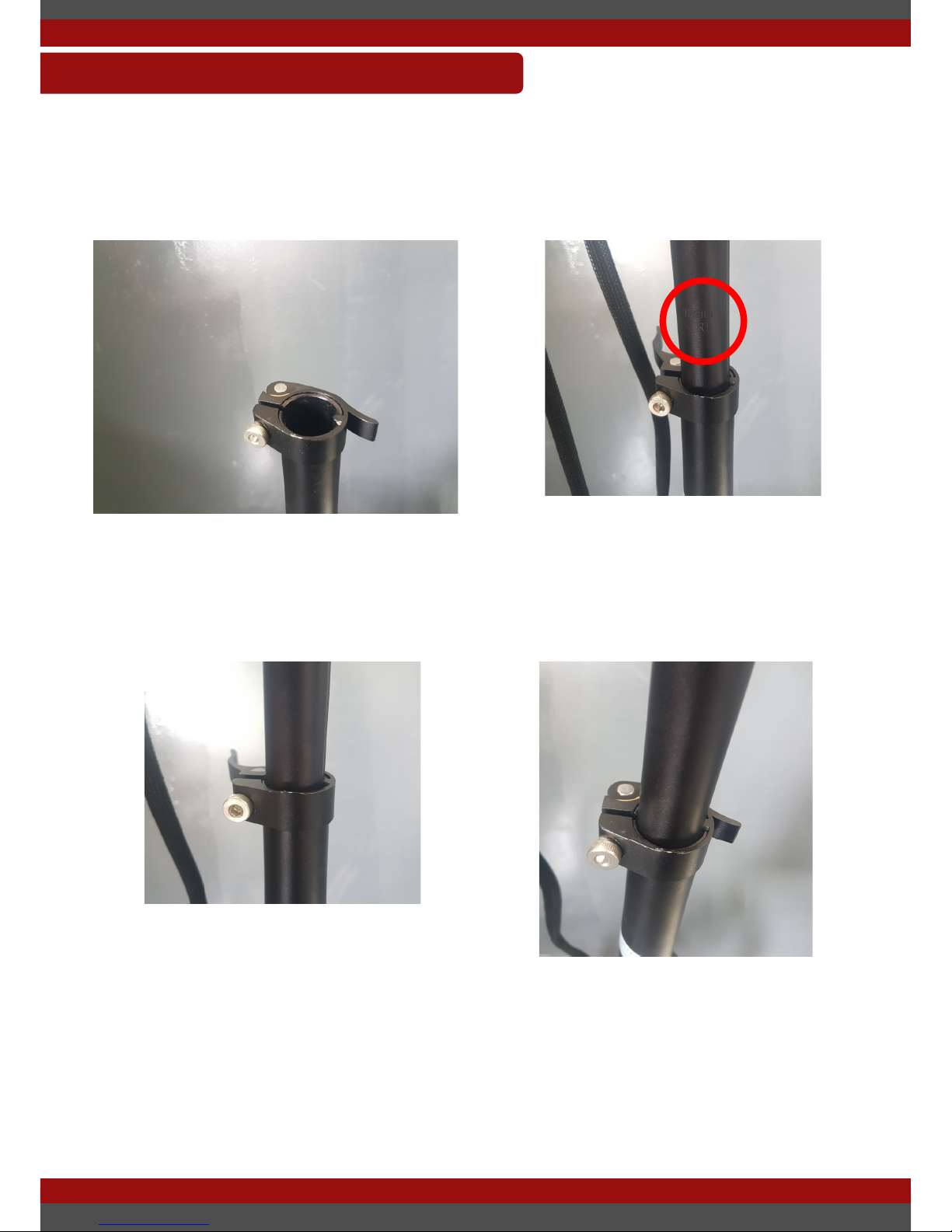
Locate the handlebar clamp, this can be seen in the top left picture. Insert the
handlebar stem into the handlebar base. One side of the handlebar is grooved so
that you cannot insert it the wrong. Though check that the cables are not twisted
before insertion.
Insert the handlebar to the desired height ensure that the engraved maximum
handlebar height is not visible. (insert them below the clamp). The maximum
handlebar height markers are shown in the top right picture. Close the clamp as
shown in the bottom two pictures. If this is too hard or two easy to close you
should adjust the tension of the clamp by tightening the thumb screw while the
clamp is open. This will ensure that the clamp is rmly closed and no nuisance
movement will occur.
Page 12
USER MANUAL OPIA
LAST UPDATED: 2/12/2016 12
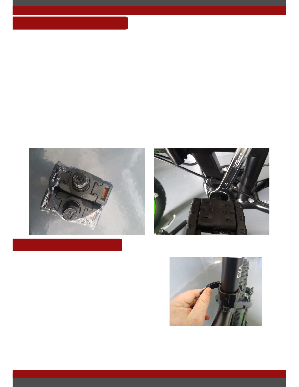
All bicycles (electric bikes included) have left and right side pedals. Make sure
you identify each one. This image shows how to identify each pedal. You can see
the ‘R’ written on this pedal, denoting this is the right side pedal, to be used on the
right side of the bike (if you were sitting on the bike).
The right side pedal mounts to the right side crank (if you were sitting on the bike)
and left side pedal on the left crank. The right side pedal is a right hand thread, it
will tighten by turning clockwise (normal). The left side pedal is a left hand thread
and will tighten by turning anticlockwise (opposite normal). It is essential not to
confuse which pedal is used where and not to cross thread the pedal. If it feels
too tight, you might have made a mistake
ASSEMBLY—PEDAL
ASSEMBLY—SEAT
Assembling the seat is the simplest
process. Just open the seat post latch.
Slide in the seat post and close the latch at
the desire height. Remember to make sure
the maximum seat height marker is below
the seat clamp at all times.
If the seat post is sliding into the clamp
when the clamp is closed, you may need to
adjust the tension of the clamp. To do this while the clamp is open rotate the
clamp clockwise to tighten. Attempt to close clamp again at the desired
tightness. If you are unable to close the clamp is may be too tight and require
loosening. Check the maintenance document for more details.
Page 13

USER MANUAL OPIA
LAST UPDATED: 2/12/2016 13
Although most assembly is completed, there are some additional checks that are
recommended before starting your rst ride.
We recommend that you check over the bike with a set of tools. Though this is
completed by dealers before dispatch and sale, though we still recommend this to
be completed regularly to ensure the safe and smooth operation of your electric
bike.
Checking the action of the brakes is at the desired tension. This is an important
step, there is nothing worse than your brakes being soft and not stopping you
adequately in those emergency situations. See the maintenance document for
more detail on how to adjust your brakes tension.
Check your tyre pressure before your rst ride. Most of the tyres are only partially
inated before shipment. So ensure that you inate your tyres up to in between
the pressure values listed on the side of the tyre wall.
Finally, we recommend that you familiarise yourself with the controls and
performance before operation. Ensure that there is also adequate space in front
of you before starting your rst ride. Completing these few things will ensure that
your rst ride is a safe one. Remember to wear a helmet at all times while
operating the electric bicycle.
Enjoy your rst ride and be sure to keep your local dealer and the manufacturer in
the loop with regards to your experiences!
ASSEMBLY—ADDITIONAL CHECKS
Page 14
USER MANUAL OPIA
LAST UPDATED: 2/12/2016 14
This section will detail some of the operation of the bicycle in particular the LCD/
handlebar display, battery and folding (if applicable). After reading through this
section you should have a good idea of how to operate the majority of the
functions of the electric bike.
OPERATION
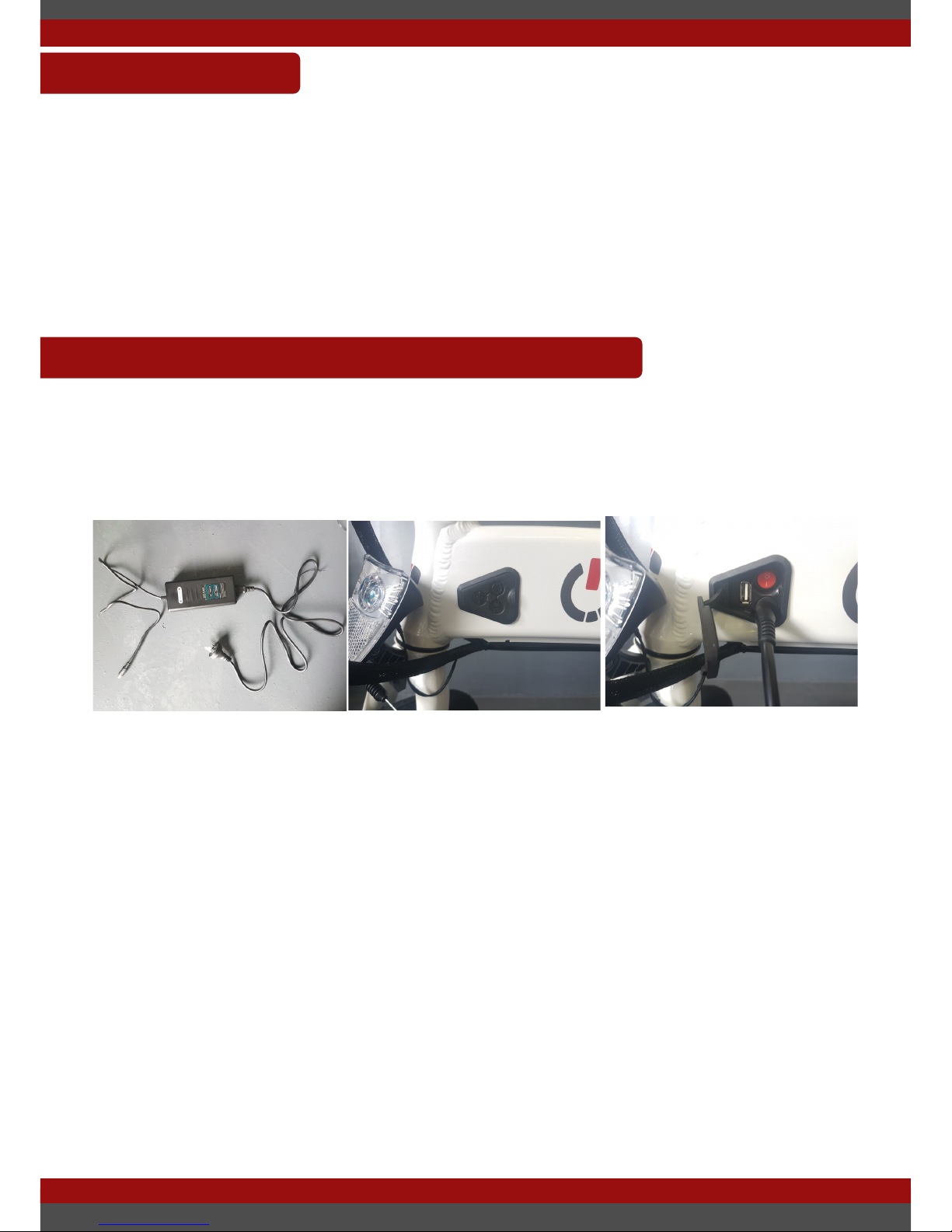
Charging the battery is a simple process and can be completed with the battery
mounted to the bicycle or when the battery has been removed from the electric
bike.
OPERATION—BATTERY CHARGING
Follow the following steps:
Plug the charger into the wall socket
Locate the charger plug on the base of the frame near the folding joint.
Shown on the left of the middle picture.
Plug in the charger to the battery.
The charger LED light will turn red while charging and green once nished
charging.
Unplug the charger from the battery and the wall socket once charging is
complete.
If charger does not stop charging after the charge time indicated in the bike
description. Disconnect the charger and contact support.
To calculate charge time: Capacity of battery (Ah) divided by the charge current
(A) = hours to charge. Usually 10.4Ah/2A = ~5 hours
Page 15
USER MANUAL OPIA
LAST UPDATED: 2/12/2016 15
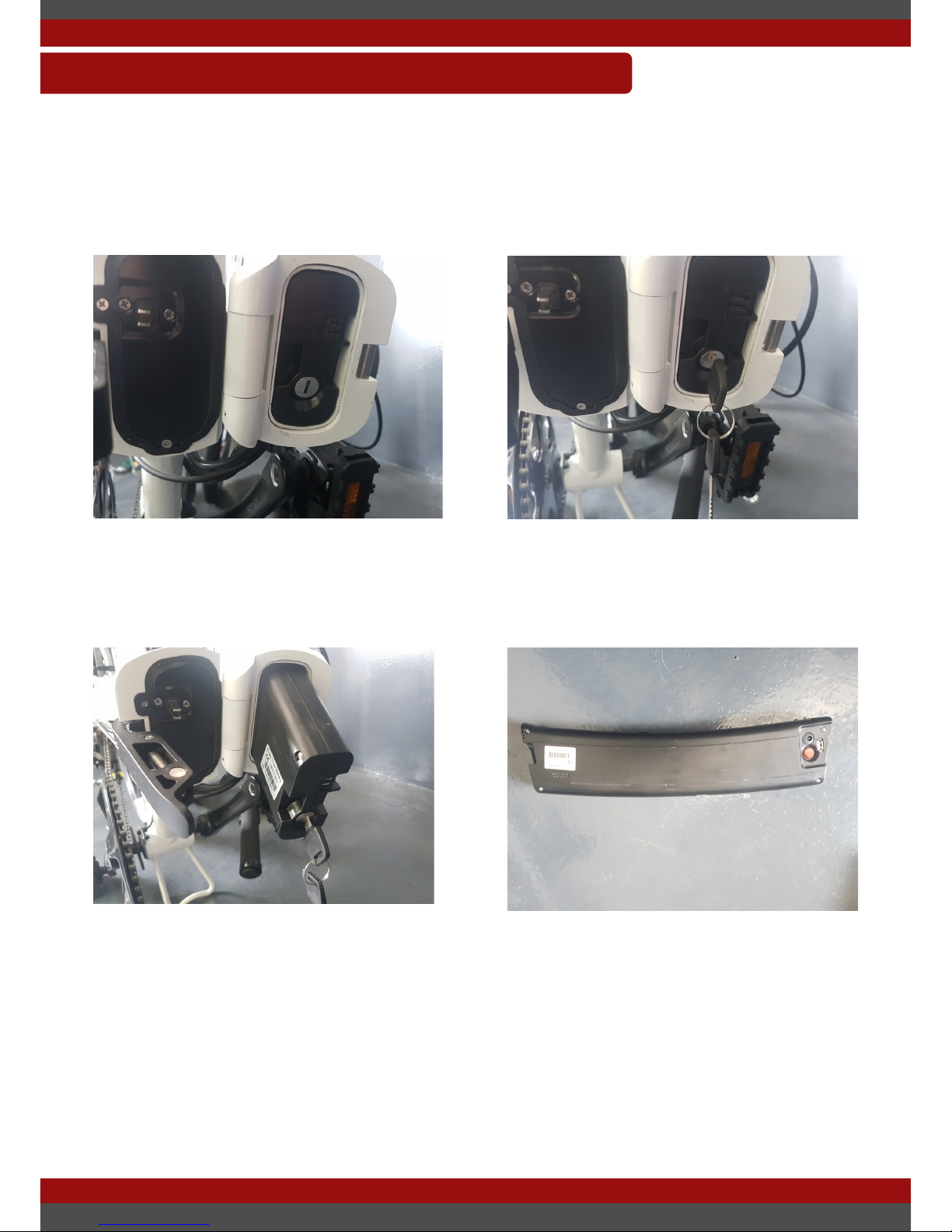
This section will detail how to remove the battery from the frame for storage,
travel or charging. To remove the battery from the bicycles frame follow the follow
steps:
OPERATION—BATTERY REMOVAL
Insert the key in the hole and turn. The battery will unlock from the frame and
allow the battery to be removed from the frame of the bike. Once the battery has
been removed you can store it or charge it as you so desire. To reinstalled the
battery. Just reinsert it into the frame and lock the battery with the key.
Firstly ensure that the bicycle has placed in a folded state (see section
Operation—Folding). Locate the key hole on the battery which is located slotted
into the frame as shown in the above pictures
Page 16
USER MANUAL OPIA
LAST UPDATED: 2/12/2016 16
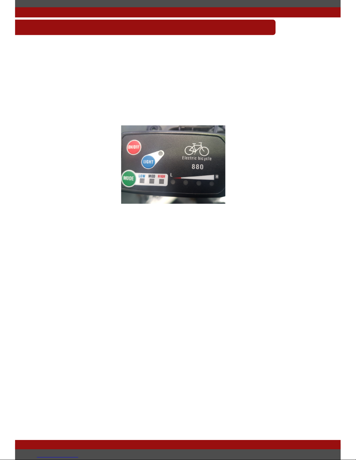
This section will help detail the basic operation of the handlebar display which
controls pedal assistance levels and shows details of the running operation of the
electric bike. For more detailed information on what is displayed please see the
manual for the individual product.
The handlebar display has three buttons. A power button, mode button and light
button.
To turn the LCD on, hold down the power button for half a second, the light will
ash and turn on. Battery meter is displayed in the bottom right and the pedal
assistance level shown on the bottom right.
To change pedal assistance level press the mode button. This will toggle the bike
between the three pedal assistance levels. Low, Medium and High.
To turn the light on/off press the light button.
To turn the system off hold down the off button for half a second.
These are the basics of the operation of the handlebar display.
OPERATION—HANDLEBAR DISPLAY
Page 17
USER MANUAL OPIA
LAST UPDATED: 2/12/2016 17
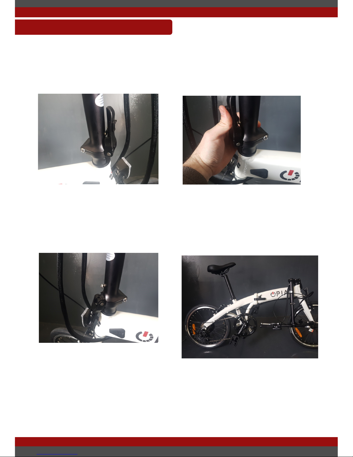
This section will detail a step by step process of how to fold you bike up for
storage or easier transport. We will start with how to fold your handlebars down.
OPERATION—FOLDING
Locate the folding mechanism for the handlebars this can be seen in the top left
picture. Rotate the plastic safety latch around anti clockwise to release the main
latch as shown in the top right picture.
Release the main latch by pull it back towards yourself as shown in the bottom
left picture. This releases the main latch and will allow you to rotate the
handlebars down towards the side of the wheel as shown in the bottom right
picture. Please ensure that no cables are caught or twisted when folding the
handlebars down, this will prevent unwanted damage to the cables.
Page 18
USER MANUAL OPIA
LAST UPDATED: 2/12/2016 18
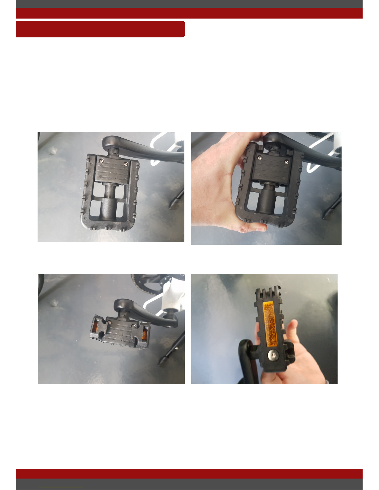
This section will help show how to fold down the pedals on the bike. Each bike
may have a different mechanism. The following photos show how to fold the
pedals down.
OPERATION—FOLDING
Push the outside of the pedal towards the bike.
Rotate the pedal upwards to fold the pedal. To unfold the pedal just rotate the
pedal back to its normal position and you should hear a click.
Page 19
USER MANUAL OPIA
LAST UPDATED: 2/12/2016 19
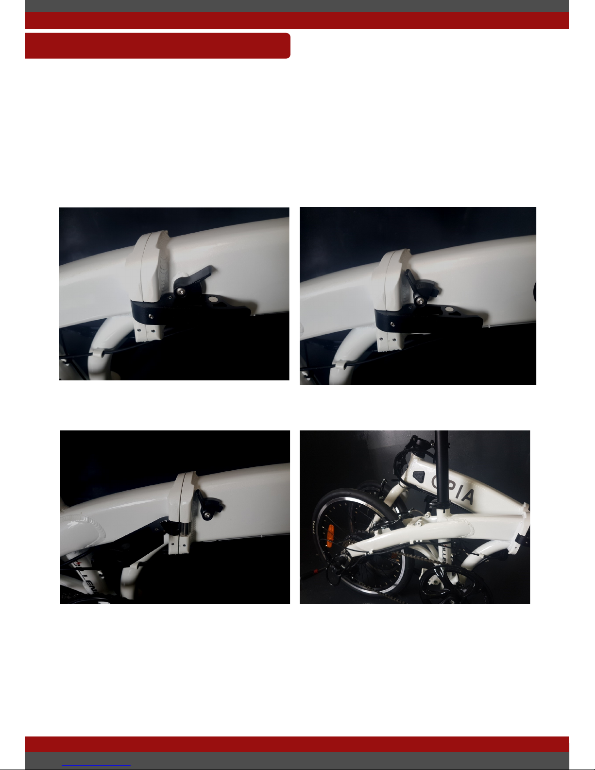
This section will help complete the initial installation of the electric bike. This is
generally only required if you purchased the bicycle online away from our retail
stores. Though the information in this section can be helpful for new users.
OPERATION—FOLDING
Locate the folding latch and lift the black safety latch upwards. Open the chrome
latch outwards to unlock the folding mechanism.
You can now fold the bike in half for storage.
Page 20

USER MANUAL OPIA
LAST UPDATED: 2/12/2016 20
This section will detail what a battery is and its features and how to maintain
good battery health over the batteries lifetime. An electric bike battery contains
multiple battery cells combined in series and in parallel to make up the Voltage
(V) and capacity (Ah) respectively. A common battery conguration is 10S4P
which means 10 cells in series and 4 in parallel which makes a 36V, 10.4Ah
(374.4Wh) battery. That’s 40 battery cells in total! As you might imagine
maintaining the health of each of these individual cells can be a difcult
proposition. Though fortunately there are built in electronic systems to make this
an automatic and simple process.
The smart battery charger will ensure that the cells are charged to maximum
capacity, without overcharging the battery, which could cause damage to the cells
and possibly even re. Our chargers are designed to stop charging when the
battery is fully charged, though we still would recommend observation and
charging in a re retardant area to ensure nothing can go wrong.
Over time each cell bank can get out of balance, which means that other cell
banks have to do more work to compensate for the lose in balance. The Battery
Management System’s (BMS) job is to ensure that each of those cells are
balanced and healthy. Each cell is balance regularly automatically by the BMS
when the cells become out of balance.
Each cell is rated for a number of cycles. A cycle is a discharge and full charge.
500 cycles is a common amount of cycles for a good quality cell. This means that
if you use it each day the battery should last 1.37 years before replacement is
necessary.
BATTERY INFORMATION
Page 21

USER MANUAL OPIA
LAST UPDATED: 2/12/2016 21
There are some things that you can do or avoid to increase the lifetime of your
battery:
Try not to discharge your battery down to 0%.
The amount that you discharge your battery is correlated to the life cycle of the
battery. Reducing the total amount that you discharge your battery will in turn
increase the longevity of the batteries life cycle.
Reduce strain in cold conditions.
Just like a human, getting started in the cold morning can be difcult. Go easy on
the bike on cold morning/days to prevent unwanted strain on the system. Avoid
going straight into full throttle or highest pedal assistance mode. Start out low
and increase over time to allow the battery to gradually warm up as opposed to
sharp increase in temperature.
Avoid operating in very high temperatures for long periods.
Lithium Ion batteries can suffer stress when exposed to high temperatures avoid
leaving your battery in sun for long periods of time, especially when fully charged.
Maintain good charging habits.
Ensure that you charge your battery after each use or when the battery is low. The
smart battery systems that are built into each component will manage individual
cells .
How do I store my battery?
It is recommended that you discharge the battery down until about 50%, remove
the battery from the frame and store in a dry, cool area. This will ensure that the
battery is in its natural state and is less likely to reduce the health/lifetime of the
battery. Do not leave your battery at a low charge for a long periods of time.
BATTERY INFORMATION—TIPS
Page 22

USER MANUAL OPIA
LAST UPDATED: 2/12/2016 22
What about reducing the voltage that you charge the batteries?
There are lots of studies and evidence about increasing the cycle life of the
battery cells by reducing the maximum voltage that you charge the battery to. It is
said that you can double the amount of cycle life by decreasing the charge voltage
of each cell by 0.1V. For a normal 36V battery that means the charge voltage
would reduce from 42V to 41V. This will decrease your maximum capacity by
approximately 14%, which in turn will decrease range. This can be difcult to
achieve with the current battery charger as you have to monitor the voltage of the
battery periodically during the charge and take it off charge once it reaches that
voltage. If you wish to undertake this style of charging we recommend that you
still charge the battery to 100% every week to ensure that the BMS can efciently
balance the cells.
There are many online resources and white papers explaining this information and
good tips for caring for your lithium ion battery. Battery university has lot of
information on all types of batteries and is a good place to start, just google
‘battery university lithium ion care’. Remember though to ensure that your
warranty remains intact only use the provided charger to charge your battery.
BATTERY INFORMATION—TIPS
Page 23

USER MANUAL OPIA
LAST UPDATED: 2/12/2016 23
How much maintenance is required?
The most common question we get is how much maintenance is required? The
basic answer is not much more than a normal bicycle. Maintaining proper care of
your bicycle is very important. Ensuring that you complete the following on a
regular basis:
Clean and oil your drive train (chain)
Clean and oil your gearing system
Check the tyre pressure is within range
Check the wear on the brakes and replace if necessary
Check the wear on the tyres and replace if necessary
Check for loose spokes on both of the wheels and tighten if necessary.
Check all fasteners
Wipe down the rest of the bike
Possibly the most important one of those points is spoke maintenance. An
electric wheel produces small amounts of vibrations that can loosen spokes over
time. It is important that you keep eye out (and ear out) for loose spokes and x
them up before it gets out of hand. Audible buzzing can be heard on occasion
when a loose spoke is present on the motor hub. This is a good indication that
spoke maintenance may be required. We would recommend any competent wheel
builder for this kind of maintenance. Though there are loads of youtube videos
that will be a great guide on xing any spoke tensioning issues you might have.
It cant be said enough that having a good maintenance routine can be one of the
best ways to catch an issue early before it becomes are large problem, saving you
time and potentially a lot of money.
MAINTENANCE
Page 24

USER MANUAL OPIA
LAST UPDATED: 2/12/2016 24
This section will detail some common faults that occur with electric bikes and
what to do in each case. Please check these before contacting support.
Before commencing troubleshooting, disconnect all components. Try not to skip
this process. There are countless times a loose plug is the cause of a problem. By
disconnecting all the plugs and then reconnecting just the crucial components
such as battery and display, this will solve any loose plug issue. Go through one
by one plugging in the other components (such as the e-brake plugs or the motor
cable) to see if any of these are the cause of the problem. In this basic state you
may discover the culprit quickly.
Troubleshooting table is on the next page
Range Extension Advice:
Reduce use of throttle. Using the throttle burns a lot more energy than
utilising the pedal assistance system, as you can ride without the need to
input any energy into the system
Use a lower pedal assistance level. It is lovely being able to max out your
pedal assistance and ride at full speed with little to no effort. Though
decreasing your pedal assistance level to a more medium to low number will
increase your range and also have the added benet of improving your health.
Choose an appropriate tyre pressure. If your tire pressure is getting a bit low,
this can be a burner of energy from the battery. Maintain your tire pressure to
the appropriate level for your ride. The tire pressure range is written on the
side of the bicycles tire wall.
Avoid mountainous areas. Although electric bikes are great at climbing hills,
hills exhaust more battery as the motor requires more energy to climb. If you
can designate a route to your location that is atter then you will likely get
more range out of your battery.
Ensure that you fully charge your battery before leaving for your journey.
Pedal more! This cant be said enough. It is easy to become lazy with an
electric bike. Pedalling will decrease strain on the battery and give you health
benet at the same time.
TROUBLESHOOTING AND ADVICE
Page 25
USER MANUAL OPIA
LAST UPDATED: 2/12/2016 25
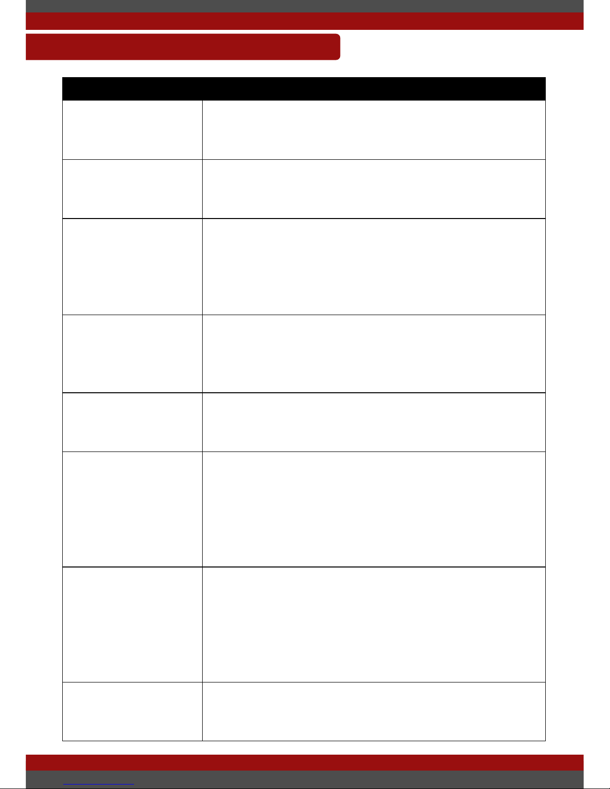
TROUBLESHOOTING TABLE
Issue Solution
Display wont turn on Check all connections from the motor controller to the
front handlebars starting with the plug coming from the
display. Ensure that the battery is switched on.
Display turns on but
the motor does not
activate
Check the motor plug from the controller. Ensure that
this plug is aligned correctly and seated very rmly.
A high pitched rattling
noise can be heard
when accelerating
Vibration from the motor is small, though is can cause
sounds in conjunction with a loose component near the
motor. Check all fasteners on the bicycle starting with
the ones closest to the motor. This could be a loose
spoke or nut on rear rack.
Rim has a wobble or
buckle
The wheel likely has a spoke tension issue. We can
recommend a wheel builder. Although there are loads of
youtube videos and websites that explain how to x
spoke problems.
There is a small
amount of movement
in the folding joint
The are a number of fasteners on the joint. Try tightening
them all. There is also a small grommet that can be
adjusted to help steady the mechanism.
My battery runs out in
a shorter distance
than what is listed in
the specication
A lot of factors effect range of the electric bike which is
why we can only offer you an approximation on range.
Try our range extension advice. If your battery is getting
on in age then it may need replacing. Contact support for
advice. We may offer a complimentary discharge test to
evaluate the health of your battery.
My battery cuts out
while riding up a hill or
while under a lot of
strain.
A battery has a safety mechanism in it called a Low
Voltage cut off. This can trigger if the battery is low in
charge and is made to perform high strain activity such
as hill climbing. As the batteries voltage will ’sag’ during
high strain activities. This is a normal to occur and is
designed to protect your battery.
The motor activates
periodically while
pedalling
It is possible that your pedal assistance sensor has
become misaligned. Send a picture of the pedal sensor
to support for advice on how to realign.
Page 26

USER MANUAL OPIA
LAST UPDATED: 2/12/2016 26
Please do not hesitate to contact Dillenger directly though our website:
http://dillengerelectricbikes.com.au/
http://dillengerelectricbikes.co.uk/
http://dillengerelectricbikes.com/
If there is any information that you would like added to these manual’s, we always
appreciate feedback from our customers.
This manual is written by the staff at EBikery with permission from Dillenger. You
can contact EBikery here:
https://www.ebikery.com.au/
Thank you for taking the time to read this document. We hope that you enjoy your
product for years to come.
CONTACT US
 Loading...