

Page 1

APACHE
User Manual
This manual describes how to safely complete nal assembly
and includes tips for use and maintenance
English
Page 2

2
SAFETY
PLEASE NOTE
Mechanical Safety Check:
Routinely check the condition of your bike. Make sure no fasteners have come loose. Perform
a visual inspection of the whole bicycle before every ride. Make sure tyres are correctly inated
within the range given on the tyre sidewall. Check your brakes for proper operation.
Your First Ride:
Be sure to pick an area away from cars, other cyclists, obstacles or other hazards to become
familiar with the controls, features and performance of your new electric bike.
We highly recommend the purchase of the Dillenger electric bike repair
toolkit. It will make your setup and ongoing maintenance much easier.
This can be purchased online.
Thank you for purchasing your new Dillenger electric bike! We know you’ll love it, and with some
care it should last for a very long time. Please read through this manual carefully before
beginning nal assembly.
THANK YOU
Page 3

3
ITEM CHECK LIST
Each electric bike is assembled under the most strict quality control standards. Upon
completion, each electric bike is test ridden by a technician inside the assembly factory to
check that every function and adjustment on the bike is perfect.
Item Check list:
• Electric bike with front wheel and handlebars
• Charger box (this may container other important parts)
• Pedals (left and right) please note the left and right pedals are not identical
• Any loose boxes may container other parts, such as a light (if where a light is provided or
purchase) so please check all packaging thoroughly
Page 4
4
Contents
THANK YOU 2
SAFETY 2
ITEM CHECK LIST 3
SUMMARY OF FINAL SETUP 5
UNBOXING 6
MAIN PARTS 7
FRONT WHEEL 9
HANDLEBARS 10
PEDALS 13
SEAT 14
FOLDING HANDLEBARS (20” MODEL ONLY) 15
FOLDING FRAME 16
FOLDING FRAME CONTINUED... 17
BATTERY OPERATION 18
LCD OPERATION 20
IMPORTANT POINTS 20
CHARGING 21
MAINTENANCE 22
TROUBLESHOOTING 23
TROUBLESHOOTING CONTINUED... 24
TROUBLESHOOTING CONTINUED... 25
CONTACT US 26
Your Dillenger bike is fully assembled in our factory and tested to our high standards.
To t into an appropriately sized shipping carton to comply with the various courier
networks, some basic parts of the bike are temporarily removed. This is so that the bike
can t into the shipping carton safely, and so that we can adequately package each part of
the bike so that it is delivered in perfect condition.
These simple instruction will show you how to perform the nal setup. Your bike may
arrive in a more assembled state than what is shown here. These are the steps required
for most customers (packaging and nal assembly can vary by country).
In summary, these are the main steps.
Step 1, Unpacking/ Unboxing
Step 2, Identify the pieces that require nal assembly
Step 3, Front wheel fastening
Step 4, Handlebar alignment and fastening
Step 5, Left and right side pedals
Step 6, Seat
Tools required:
Allen keys (5 and 6mm)
Spanner (15mm)
These are provided and can be found in the charger box.
Other equipment not provided:
Bike pump (or service station car tyre pump)
Page 5

SUMMARY OF FINAL SETUP
5
Your Dillenger bike is fully assembled in our factory and tested to our high standards.
To t into an appropriately sized shipping carton to comply with the various courier
networks, some basic parts of the bike are temporarily removed. This is so that the bike
can t into the shipping carton safely, and so that we can adequately package each part of
the bike so that it is delivered in perfect condition.
These simple instruction will show you how to perform the nal setup. Your bike may
arrive in a more assembled state than what is shown here. These are the steps required
for most customers (packaging and nal assembly can vary by country).
In summary, these are the main steps.
Step 1, Unpacking/ Unboxing
Step 2, Identify the pieces that require nal assembly
Step 3, Front wheel fastening
Step 4, Handlebar alignment and fastening
Step 5, Left and right side pedals
Step 6, Seat
Tools required:
Allen keys (5 and 6mm)
Spanner (15mm)
These are provided and can be found in the charger box.
Other equipment not provided:
Bike pump (or service station car tyre pump)
Page 6
6
UNBOXING
Unboxing your Dillenger will be very exciting, but it’s important to take care when
unboxing the bike as it’s possible to accidentally damage the bike or misplace crucial
parts. It’s also much easier to unbox the bike with someone to help you.
Remove the protective packaging from the bike carefully with a pair of scissors or a box
cutter. Make sure you don’t misplace any components in the lose packaging (there can be
quite a lot of protective packaging used).
After you’ve taken your Dillenger out of it’s shipping carton, you should have these parts:
1. The Complete Bike
2. Front Wheel
PLEASE NOTE
The keys will be securely fastened to the frame or handlebars of
your bike. Make sure you do not lose these as they are coded and a
replacement set can only be tted in a Dillenger factory.
Page 7

7
MAIN PARTS
After you’ve taken your Dillenger out of it’s shipping carton, you should have these parts:
1. The Complete Bike
2. Front Wheel
Page 8

8
3. Handlebars (Attached by the Cabling)
4. Charger
5. Pedals
Note: These can be in the same box as the charger, or fastened to the bike separately.
6. Seat
Note: These can be in the shipping carton or fastened to the bike separately.
Simply insert the front wheel into the front forks, with the brake disk lined up to t into
the brake calipers. Insert the washer on both sides of the wheel such that the ‘hook’ part
of the wheel ts into the slot where the axle enters. Screw on nuts and tighten with 15mm
spanner.
Note: It may be easier to do this step with the bike ipped over on its seat and handlebars. Just
be careful of the display on the ground you are constructing on.
Page 9

9
FRONT WHEEL
Simply insert the front wheel into the front forks, with the brake disk lined up to t into
the brake calipers. Insert the washer on both sides of the wheel such that the ‘hook’ part
of the wheel ts into the slot where the axle enters. Screw on nuts and tighten with 15mm
spanner.
Note: It may be easier to do this step with the bike ipped over on its seat and handlebars. Just
be careful of the display on the ground you are constructing on.
Wheel is place into the axle slot on the front forks
Washer is place on axle as shown above and the nut is fastened securely
Page 10

10
Stem and handlebars are now in position on the headtube.
HANDLEBARS
The handlebars will be connected by the cables and wires, all that’s required for nal
setup is to mount the handlebar stem onto the head tube as shown here:
You can remove a number of the black spacer rings on the head tube, leaving 2. These 2
can be placed in any arrangement. In these photos we have the handlebars in the highest
position, with 2 spacers under the stem. Make sure none of the cables are twisted or
too tight (you may have the handlebars twisted). Tighten as shown here, making sure
the handlebars are aligned to the front wheel. This step fastens the stem down onto the
headtube to remove any vertical play:
Page 11

11
Stem and handlebars are now in position on the headtube.
Page 12

12
All bicycles (electric bikes included) have left and right side pedals. Make sure you identify
each one. This image shows how to identify each pedal. You can see the ‘R’ written on
this pedal, denoting this is the right side pedal, to be used on the right side of the bike (if
you were sitting on the bike).
The right side pedal mounts to the right side crank (if you were sitting on the bike) and
left side pedal on the left crank. The right side pedal is a right hand thread, it will tighten
by turning clockwise (normal). The left side pedal is a left hand thread and will tighten
by turning anticlockwise (opposite normal). It is essential not to confuse which pedal is
used where and not to cross thread the pedal. If it feels too tight, you might have made a
mistake.
The pedals are designed this way so that the act of pedaling (while riding) does not
loosen the pedals over time.
Screw in the pedals as described above for both left and right. Depending on the type of pedal
Align the handlebars sp that the wheel and handlebar stem are ‘parallel‘ and fasten the
stem onto the headtube. Tighten each side evenly. This is the nal step in fastening the
handlebars correctly.
Align the handlebars and fasten the stem onto the headtube by tightening each allen bolt
evenly using the provide allen keys
Page 13

13
PEDALS
All bicycles (electric bikes included) have left and right side pedals. Make sure you identify
each one. This image shows how to identify each pedal. You can see the ‘R’ written on
this pedal, denoting this is the right side pedal, to be used on the right side of the bike (if
you were sitting on the bike).
Pedal sides are denoted with ‘L‘ and ‘R‘ as shown circled red in above photo
The right side pedal mounts to the right side crank (if you were sitting on the bike) and
left side pedal on the left crank. The right side pedal is a right hand thread, it will tighten
by turning clockwise (normal). The left side pedal is a left hand thread and will tighten
by turning anticlockwise (opposite normal). It is essential not to confuse which pedal is
used where and not to cross thread the pedal. If it feels too tight, you might have made a
mistake.
The pedals are designed this way so that the act of pedaling (while riding) does not
loosen the pedals over time.
Screw in the pedals as described above for both left and right. Depending on the type of pedal
they can be tightened using an allen key on the inside as shown above or by tightening with a
spanner inbetween the pedal and the crank (model dependant).
Page 14

14
SEAT
This is the easy part. Simply insert your seat to the desired height (about hip height) as
shown below:
The seat clamp is aligned with the groove and loosly tightened using thumb screw
The seat is placed into the hole and adjusted to the desired height then the clamp is closed to
lock the seat in position
Page 15

15
Probably the most popular feature of a fodling bike is its ability to moved or stored in
places that a bike wouldn’t normally t. Following the following steps to fold down your
bikes handlebars.
1. Locate the clamp section on the handlebars
2. Loosen clamp by rotating screw handle
3. Gently lower the handlebars down ensure no cables are caught
4. Your handlebars are now folded down
Turn the clacmp handle anticlockwise to open the clamp
Gently lower the handlebars down
FOLDING HANDLEBARS (20” MODEL ONLY)
Page 16
FOLDING FRAME
16
PLEASE NOTE
Ensure that the bike is turned o by pressing the controller button
beofre attempting to fold the bike.
Following the following steps to folding you bike into its folded state:
1. Locate pedals and fold pedals up (Optionally remove seat for more space)
2. Locate the clamp section on the frame and check the bike if turned o
3. Undo black safety latch and open lever lock
4. Using two hands rotate open the frame
5. Continue to rotate the frame around ensuring no cables get caught in the process.
6. Lay bike onto support fram below crank set
Step 1: Push pedal into the crank and rotate
Step 2 and 3: Undo Safety Latch
Page 17

FOLDING FRAME CONTINUED...
17
Step 3 and 4: Push pedal into the crank and rotate
Step 5 and 6: Lay bike onto support frame located under the crank set
Congratulations you have now successfully folded your Dillenger bike for storage or easy
transport.
Page 18

18
BATTERY OPERATION
The battery for your Dillenger is the most expensive single component and the most
crucial. The battery can be removed following these steps. Use the key provided to unlock
the battery:
The key hole and charging plug is located on the bottom of the frame near the folding join
The key is placed in the smaller hole of the two. Turn the key from anticlockwise to unlock and
clockwise to lock (while looking at the key, opposite if looking down at the frame while turning).
To remove the battery the bike must be in its folded state (see Folding Section). Once
folded and key is turned to the unlocked position. The battery is located on inside the
right side of the frame. pull the handle to remove. If the battery does not come out check
the key position and try again.
Remove the battery by pulling the handle shown above after unlocking the battery with the key
You may remove the battery to charge or the battery can be charged in the frame. For
transport by car, we recommend taking the battery out of the bike and storing inside
the car, in a safe place. When mounting the battery back into the frame, insert it in the
same fashion that it was removed. The base of the battery should be inserted rst and
pushed into the frame of the bike slowly. Once the battery is reinsterted into the bike the
key should be locked. It is a tight t and this may take a couple of attempts to become
procient.
It is very important that the battery is locked into place before you use the bike again. Pull
gently on the battery handle to make sure it is denitely locked.
Place the battery back into the chassis and checked that it is secure and locked by gently pulling
Page 19

19
To remove the battery the bike must be in its folded state (see Folding Section). Once
folded and key is turned to the unlocked position. The battery is located on inside the
right side of the frame. pull the handle to remove. If the battery does not come out check
the key position and try again.
Remove the battery by pulling the handle shown above after unlocking the battery with the key
You may remove the battery to charge or the battery can be charged in the frame. For
transport by car, we recommend taking the battery out of the bike and storing inside
the car, in a safe place. When mounting the battery back into the frame, insert it in the
same fashion that it was removed. The base of the battery should be inserted rst and
pushed into the frame of the bike slowly. Once the battery is reinsterted into the bike the
key should be locked. It is a tight t and this may take a couple of attempts to become
procient.
It is very important that the battery is locked into place before you use the bike again. Pull
gently on the battery handle to make sure it is denitely locked.
Place the battery back into the chassis and checked that it is secure and locked by gently pulling
the handle
Page 20
20
LCD OPERATION
We have an LCD manual on the product page online, or follow this link:
Dillenger C965 Manual
IMPORTANT POINTS
Please consider these important points for best use:
Keys:
The keys for your bike are zip tied to your handlebars. You will have 2 keys so please keep
one as a spare separately. Replacing keys can only be done in the Dillenger Warehouse.
Battery Indicator:
The battery light indicator on the battery is not an indication of battery charge. The only
approximation of battery charge level is on the LCD display. The only accurate way to
know that the bike is 100% charged is by charging it until the charger light shows it is
fully charged (next page). Conversely, the only way to accurately know that the battery
is at is to use the bike until the LCD cuts out and does not turn back on. You do not risk
damaging the electric system by running the bike at. Just make sure you charge the bike
after every ride.
Maintenence:
Make sure you routinely check the tightness of key fasteners (nuts and bolts) such as the
front wheel, rear wheel, seat, handlebars, forks, pedals, brakes, etc.
Battery Charge:
Make sure you keep the battery topped up as often as practical. Charge the bike after
every use, at least once a month if not being used and before each ride if you have not
charged it in a week. It is not necessary to run the battery down at all. Leaving the battery
at runs the risk of completely depleting the cells which could cause premature battery
failure.
Tyre Pressure:
Make sure your tyres are pumped up to the correct PSI, which is indicated on the tyre side
wall.
Power Switch:
The battery has an on/o switch located near the handle. You must turn the switch on
before powering up the bike, and turn it o after use. The LCD display turns the system
on, once the battery is turned on.
1. Plug the charger into the wall socket/
outlet, just like a laptop of mobile phone
charger.
2. Check that one of the charger indicator
lights glows green.
3. Plug the charger, (battery end) into the
battery plug carefully, making sure it is all
the way in. Do not force it if there is an
obstruction.
4. The charger indicator lights should glow
red whilst charging.
5. Once one of the charger indicator lights
changes from green to red, the battery is
fully charged.
There is no way to over-charge the battery.
When it is full, the charger will stop
charging the battery automatically.
Charging time can vary from 1 to 5 hours if
fully empty.
The battery should be charged once every
month as a minimum to maintain healthy
cells.
The best way to charge your battery is
to plug it in after every use, and leave it
on charge until the indicator light shows
the battery is fully charged. It is not good
practice to partially charge the battery.
Page 21

21
CHARGING
1. Plug the charger into the wall socket/
outlet, just like a laptop of mobile phone
charger.
2. Check that one of the charger indicator
lights glows green.
3. Plug the charger, (battery end) into the
battery plug carefully, making sure it is all
the way in. Do not force it if there is an
obstruction.
4. The charger indicator lights should glow
red whilst charging.
5. Once one of the charger indicator lights
changes from green to red, the battery is
fully charged.
There is no way to over-charge the battery.
When it is full, the charger will stop
charging the battery automatically.
Charging time can vary from 1 to 5 hours if
fully empty.
The battery should be charged once every
month as a minimum to maintain healthy
cells.
The best way to charge your battery is
to plug it in after every use, and leave it
on charge until the indicator light shows
the battery is fully charged. It is not good
practice to partially charge the battery.
Page 22
22
MAINTENANCE
PLEASE NOTE
Any modications to any Dillenger product that isn’t approved by
Dillenger will void your warranty.
Keep your bike clean! There’s nothing worse than having to work on a dirty bike...
Also keep in mind the usual bike maintenance like tyre pressures, brake pads, etc...
The motor is a sealed unit and requires no maintenance during the design life.
Lastly (just to reiterate) it’s important that you charge the battery at least once every month
to ensure the battery maintains a safe storage level.
A little extra maintenance is required over
and above a normal bicycle.
One of the main things you may come across
is that your spokes need to be tightened
more often than a non-electric wheel. Our
wheels use 12G and 13G spokes which
handle the load and torque of these motors
very well, but are more susceptible to
coming loose.
A spoke-tightening tool such as the one
including in the Dillenger hub motor
conversion toolkit, is ideal.
Check the tightness of each spoke ideally
after the rst 100km and then every 500km.
As well as caring for your spoke tension
it’s important to do a check on all of your
fasteners every few months. It never hurts to
go over your bike with tools, tightening and
checking everything that can be checked. This
will ensure you have a safe and well-serviced
bike.
Page 23
23
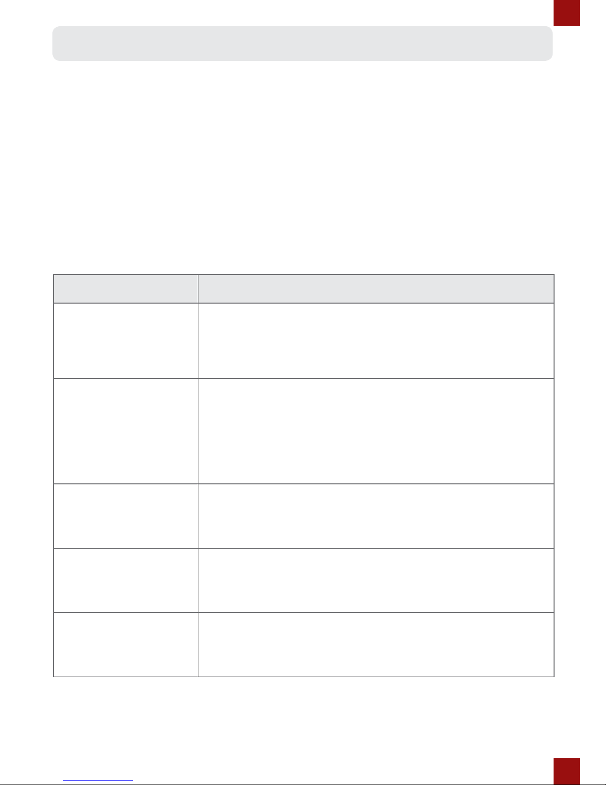
TROUBLESHOOTING
Fault Solution
Display turns on, but
motor does not
Activate
Check the motor plug from the controller. This is a very sti
connection and will not work unless the plug is all the way in to
the indicator line. The twisting of the handlebars can sometimes
cause the plug to pull out slightly if there is not enough slack in
the motor cable.
A high pitched rattling
noise can be heard
when accelerating
The vibration of the motor is very small, but at this frequency it
can do some odd things to the other components on the bike
if they are loose. For example a loose spoke or even a bolt on
your rear rack. If something is just a little bit loose, sometimes
this can reverberate and make a harsh high pitch rattling sound.
Nothing is broken or wrong, you just have to identify the loose
part!
Rim has a buckle or
spokes coming loose
all the time
We would recommend a competent wheel builder to x any
major spoke tension issues, however there are some really good
youtube tutorials on how to adjust spoke tension.
Spokes has snapped
or missing
Dillenger stocks spare spokes for very reasonable prices, just
check out our spares section online and you can nd the right
type and length for your product.
Display won’t turn
on, unless the battery
charger is plugged in
Check all the connections, make sure the battery is charged. If
the display turns on only when the battery charger is plugged in,
you will have to submit a service ticked with this information.
Dillenger’s troubleshooting advice will take you through a logical way to diagnose
any issues that may arise during installation and use.
Before commencing troubleshooting, disconnect all components. Do not short
cut this process. There are countless times a loose plug has caused grief. By
disconnecting all the plugs and then reconnecting just the crucial components, this
will solve any loose plug issue.
Go through one by one plugging in the other components (such as the e-brake
plugs or the motor cable) to see if any of these are the cause of the problem. In this
basic state you may discover the culprit quickly.
Page 24
24
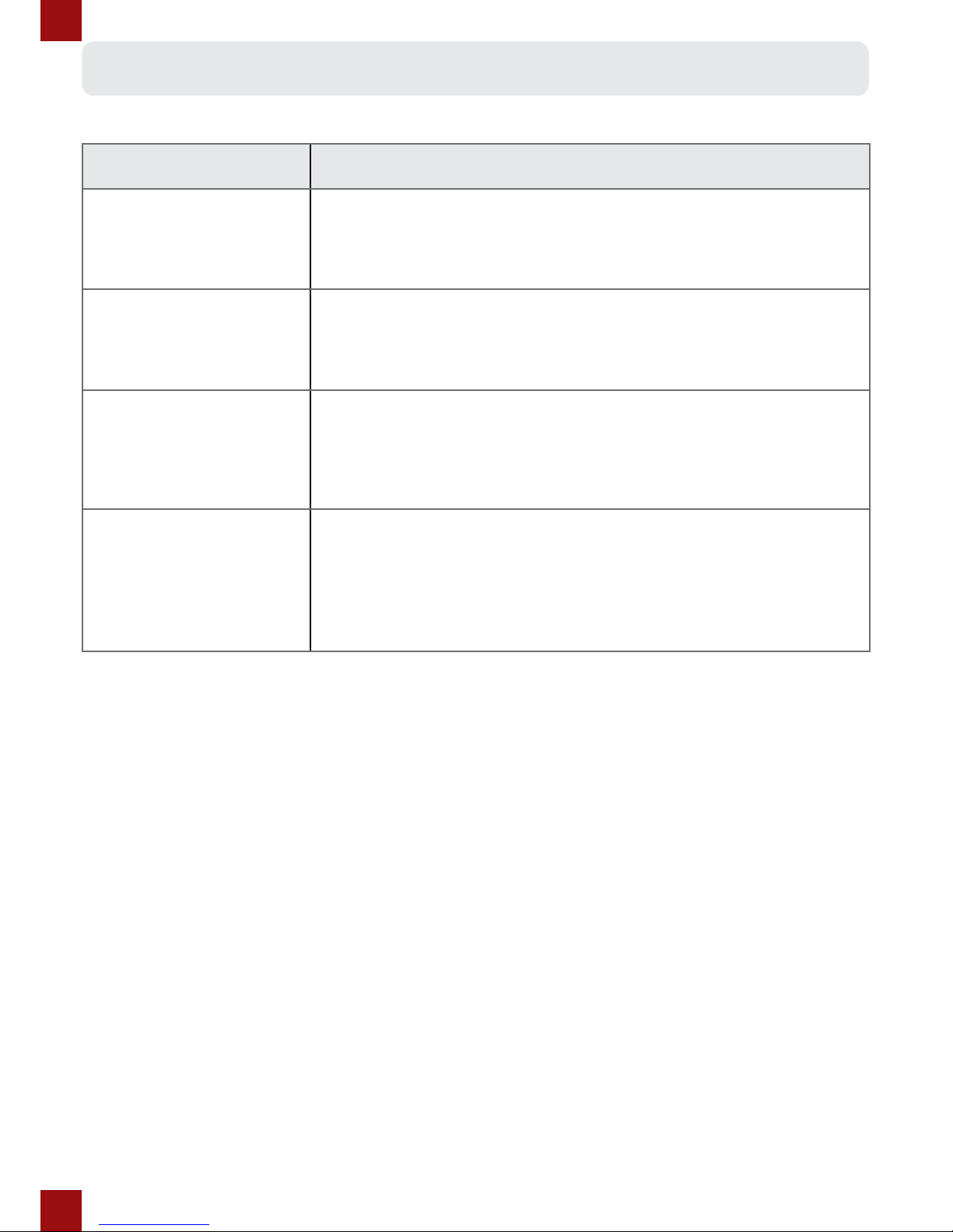
Fault Solution
Error message on the
display
Please refer to display manual for error code denition and if
needed, report the error code to Dillenger in a service ticket.
My kit looses power
over bumps
Check all connections to make sure all the plugs are all the way
connected. Check that the battery is locked to the cradle and not
loose. A momentary discontinuity in power will turn the kit o.
My battery cuts out
intermittently
If the battery is low on power, or you are going up a very steep
hill with a load on the motor, you will likely experience a voltage
cut-o if you have overloaded the controller, or dropped the
voltage below the low voltage cut-o, which is more prevalent at
low power. This isn’t a fault with the kit, it’s just physics.
I would like my
battery capacity
tested
Please contact Dillenger by submitting a support ticket to
arrange the return of your battery for testing. If the battery tests
above 85% capacity within the rst year (from purchase date)
you will be liable for return freight. If it is tested and is
under capacity within the warranty period, your battery will be
replaced.
TROUBLESHOOTING CONTINUED...
Page 25

25
Range extension:
If you’re not getting the approximate quoted range out of your e-bike system, take the
following steps:
1. Battery indicator lights – full charge.
The LED and LCD battery level displays are a basic indication of battery charge, but they
are based on voltage which is variable and not a true indication of battery capacity. The
only accurate indication of a full charge, is having charged the battery and the battery
charger lights glowing green to indicate that the battery is fully charged.
2. LED/LCD indicator light – running low
Some customers nd that the LED/LCD charge indicator can lead them astray in terms
of how far the bike will go on low power. You don’t risk damaging the system by riding
all the way to the controller low voltage cuto. Keep riding on pedal assist even after the
last battery indicator bar starts blinking.
3. Hills/riding style/other factors
The ranges quoted are from real world testing, with some hills and some at areas. If
your commute involves a lot of hills, that’s going to impact on the range. High powered
e-bikes are especially susceptible to being drained a lot more on hills. If you need to
purchase a second charger to charge the battery at half way, or this can be a cost eect
way of doubling your range.
4. General tips
• Make sure the wheels are running free (rubbing brakes can halve your range quite
easily)
• Keep the battery topped up between uses (this is very important)
• Make sure the tyre pressures are at optimum (ideal pressures are written on the tyre
side wall)
• Select the right gear for assisting up hills (the steeper the rise, the lower the gear
needed)
If you would like to submit a Dillenger service ticket, please go to this URL:
Support Site
TROUBLESHOOTING CONTINUED...
Page 26

26
CONTACT US
Dillenger Head Oce
3/13 Olympic Circuit
Southport
QLD 4215
AUSTRALIA
Tel.: +617 5532 9235
dillenger.zendesk.com
www.dillengerelectricbikes.com
© Dillenger 2015
 Loading...