

DIGWDF XBee/ESP Snap-In
QTY
Description
Part #
Source
1
3.3v regulator, 500ma (optional, but preferred part)
3.3v regulator, 800ma (cheaper substitute for above)
UA78M33CKCS
LM1117T
Mouser.com
Taydaelectronics.com
1
3.3v regulator 100ma (optional – for XBee in receive mode only
L78L33
Taydaelectronics.com
1
.1uf non-polarized capacitor
1
100uf 16-volt electrolytic capacitor (optional, for ESP)
1
5-pin male header (optional)
1
1x5 female header (optional)
1
2-pin male header (optional)
1
Jumper shunt (optional)
2
Female XBee headers (optional, for XBee only)
2
1x4 stackable headers (optional)
1
3.3v Zener diode (optional, Xmit mode only)
1
XBee module (optional, use Series 1 only)
1
ESP8266 module (optional, use ESP-01 style)
1
2x4 female header (optional, ONLY if ESP8266 module is used)
Assembly & User Guide
Overview
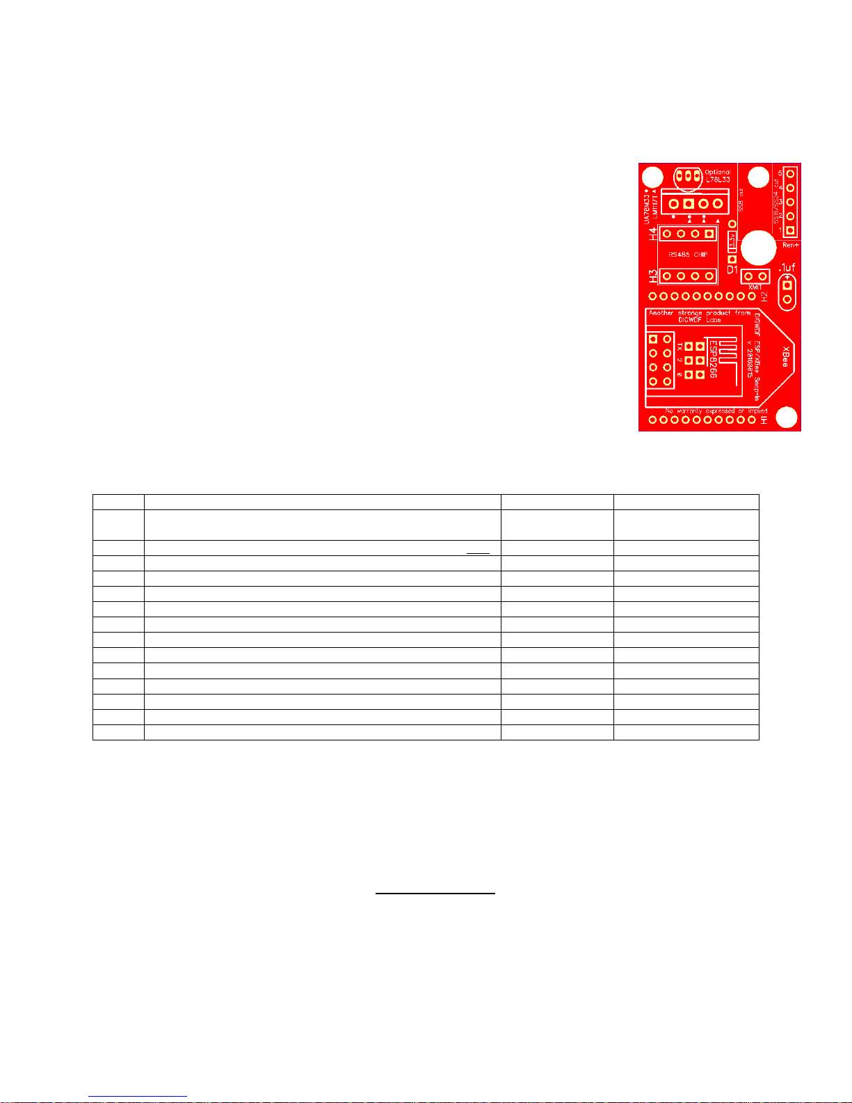
The ESP/XBee Snap-In is a small, inexpensive multi-purpose wireless adapter
board. It can facilitate using an XBee radio or the ESP-01 module for wireless
reception or the XBee radio if used as a transmitter. Created in 2011, it was the
first adapter that was designed to plug directly into the U5 ST485BN socket of
the Renard SS8, SS16 or SS24 controller for wireless control using the tried-andtested XBee radio. With the addition of a 5-pin Renard Plus female header, the
Snap-in can plug directly onto the header of the same configuration on any
Renard Plus controller. Subsequent developments in the wireless industry have
expanded its capability with the inexpensive ESP8266 module for full Wi-Fi
control in place of the popular XBee. The Snap-In is primarily used as a
receiving unit but can also be used as a transmitter or XBee programmer when
using an XBee radio and interfaced to a computer via an inexpensive USB->TTL
adapter.
BOM – Bill of Materials
Parts substitutions
Notice that almost every part is listed as ‘optional!’ This is because there are many options for
building and using this adapter. Before ordering or installing any parts, the user is highly
encouraged to READ THROUGH this guide to determine exactly how the adapter will be used first
because suggestions will be made for which parts are needed for various configurations. Here are a
few starting guidelines:
If you plan to use an XBee radio in receive mode only, the lower-output L78L33 voltage
regulator will suffice; otherwise, the UA78M33 or LM1117T regulator is required.
If you plan to use the ESP8266 module, you do not need the female XBee headers, the 2-pin
header and shunt jumper or the 3.3 Zener diode. You cannot transmit with the ESP8266
module and this adapter.
DIGWDF XBee/ESP Snap-In Assembly & User Guide – v 20170308 -Page 1
If you do not plan to use the adapter in a transmitting mode with an XBee radio, you do not
SS24/SS16 with
BLUE; note that the
SS24/SS16 with
BLUE; note that the
need the 2-pin header and shunt jumper or the 3.3 Zener diode.
If you do not plan to use the adapter with an SS8, SS16 or SS24 controller, you do not need
the two 1x4 stackable headers.
If you do NOT plan to use an ESP8266 module, do NOT install the 2x4 female header.
If you plan to use the adapter with a Renard Plus or other controller, you do not need the
1x4 stackable headers because you will not be plugging it into a chip socket on the
controller.
If you plan to plug the adapter directly onto the 5-pin header on a Renard-Plus controller,
you need the 1x5 female header mounted on the BOTTOM side of the PCB; you also do not
need the 5-pin male header on the top.
If you want the most future flexibility with this adapter and want to assemble a sort of
“universal snap-in adapter” that can work with either an XBee or an ESSP8266 module,
install all the parts except the L78L33 regulator, the 1x5 female header, the two 1x4
stackable headers and the 2x4 female header for the ESP8266 module. Then later on, you
can simply plug an ESP Snap-In module in place of the XBee module. To connect the adapter
to your controller, you’d use connecting cables from the 5-pin header, attaching them to
appropriate locations on your controller. More information about that is included later.
SS8, SS16 and SS24 installations
If you plan to plug the adapter into the U5 dip socket on an SS8, SS16 or SS24 controller, the SnapIn PCB has a large hole that can fit over the 47uf capacitor next to the U5 socket. It should fit
perfectly on the SS24 controller, but because the RJ45 jacks are spaced slightly differently on the
SS8 and SS16, the adapter requires a slight modification to fit on either of them; trim the PCB
corner a bit on the indicated “cut” lines for either the SS8 or SS16. The PCB should be cut BEFORE
installing any parts; it can be cut with a Dremel tool or a hacksaw. Go slow and cut accurately. Note
that cutting off any of the corner of the board will remove the 5-pin connection header that’s used
for Renard Plus controllers.
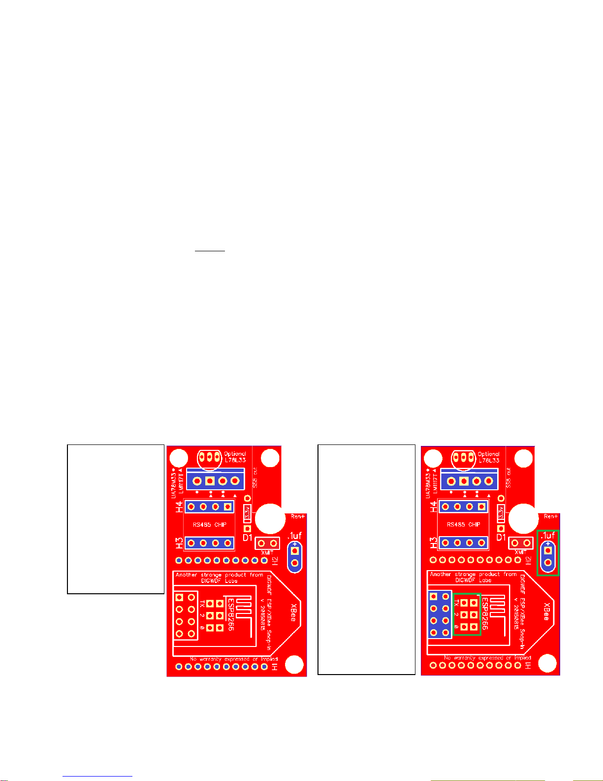
XBee radio
Required parts are
highlighted in
SS8 requires a
larger cut-out in
the upper right
corner of the PCB
than the SS16 or
SS24.
ESP-01 module
Required parts are
highlighted in
SS8 requires a
larger cut-out in
the upper right
corner of the PCB
than the SS16 or
SS24. A 100uf cap
is suggested in
place of .1uf . Also
remember to
solder the proper
TX/2/0 circuit for
your version of the
ESP firmware.
DIGWDF XBee/ESP Snap-In Assembly & User Guide – v 20170308 -Page 2
With ESP-01
convenience to any RP
With XBee radio
Pin 5 = Data
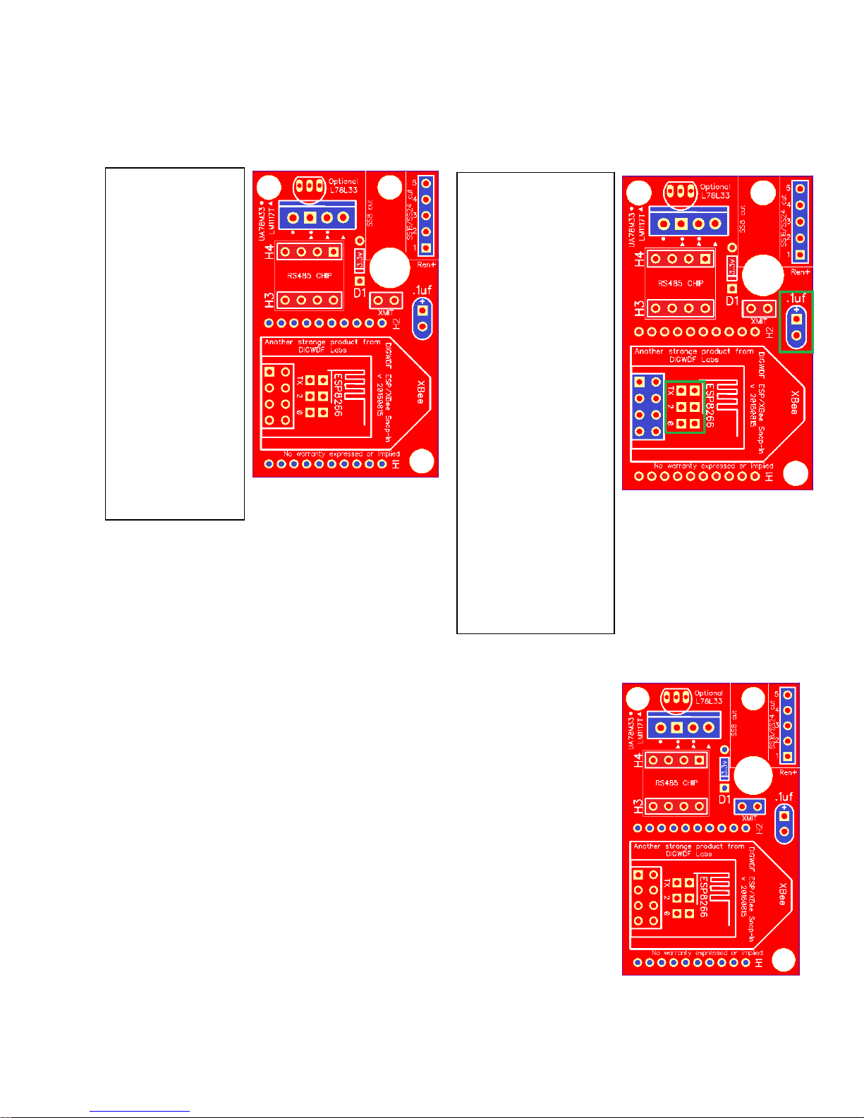
Renard-Plus (and other) installations
Required parts are
highlighted in
BLUE. Install the
female 5-pin
header on the
BOTTOM of the
PCB for plug-in
convenience to any
RP controller. For
other controllers,
install the 5-pin
male header on the
TOP and use
connection cables
to connect to your
controller:
Pin 1 = +5v
Pin 3 = GND
module
Required parts are
highlighted in BLUE.
Install the female 5pin header on the
BOTTOM of the PCB
for plug-in
controller. For other
controllers, install the
5-pin male header on
the TOP and use
connection cables to
connect to your
controller:
Pin 1 = +5v
Pin 3 = GND
Pin 5 = Data
Note: a 100uf cap is
suggested in place of
.1uf . Also remember
to solder the proper
TX/2/0 circuit for
your version of the
ESP firmware.
Snap-In as a Transmitter/XBee Programmer
If you plan to use the Snap-In with your computer as an XBee transmitter,
install the parts as noted in blue to the right: It’s suggested to install the
male 5-pin header in the upper-right corner of the PCB to make it easy to
connect it to your computer using an USB-TTL adapter as follows:
Pin 1 = +5v
Pin 3 = GND
Pin 4 = TX data from the USB-TTL adapter
Install a jumper shunt on the 2-pin XMIT header.
The transmitter mode only applies to using an XBee radio and not an ESP-01
module.
XBee Programmer: connect the Snap-In pin 5 (of the 5-pin header) to the
RX line of the USB-TTL adapter for duplex communication to the XBee radio
and use your XBee’s XCTU software to connect to the USB-TTL adapter and
change the settings in your XBee radios.
DIGWDF XBee/ESP Snap-In Assembly & User Guide – v 20170308 -Page 3
Assembly
Depending on how you plan to use the adapter, simply follow the normal rule-of-thumb for
assembling electronic projects: install the parts by their height starting with the shortest and
graduating to the tallest parts.
Determine how the snap-in will be used first, then select the parts necessary for your
application.
Sort the parts into shortest to tallest order, then install them.
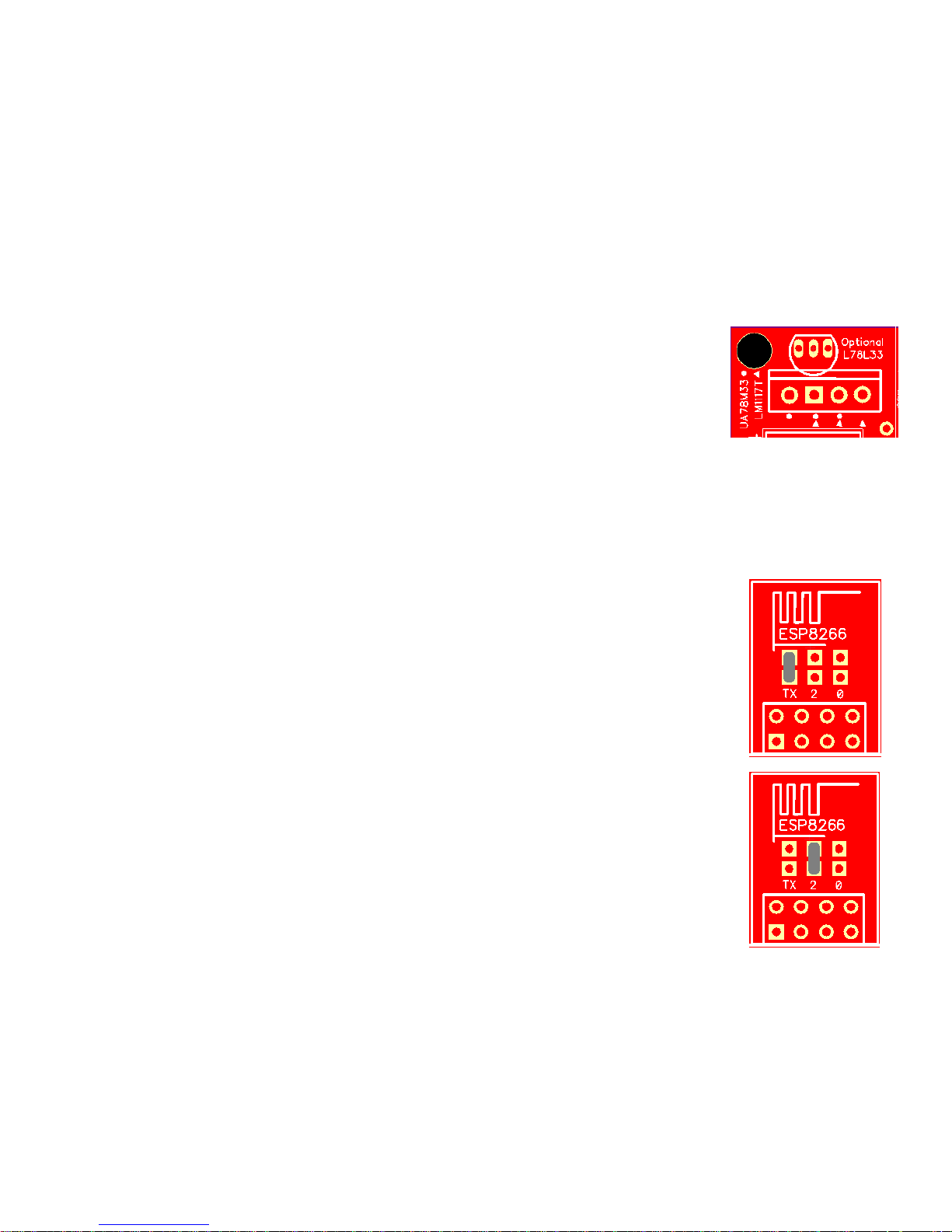
3.3v regulator – 3 types are available; be sure to mount your choice in the proper position,
matching the outlines on the PCB:
o The UA78M33 regulator’s position is marked with small dots
o The LM1117T regulator’s position is marked with small triangles
o The LM78L33 regulator is near the TOP of the PCB; be sure to
orient the
Setting the ESP Circuit Connection (Does not apply if using an XBee)
Depending on which version of the ESP firmware you use, you will need to connect two circuit pads
on the Snap-In with a blob of solder. The ESP module will send data to your controller unless you do
this step properly. You may apply the blob of solder on either the top or bottom side of the PCB.
If you use Bill Porter’s original ESPixelStick Firmware for the ESP module,
connect the two pads marked ‘TX’. This sends the data to the controller via
the ESP’s TX pin. (Bill Porter was instrumental in adding both Renard and
DMX serial capability to Shelby Merrick’s ESPixelStick firmware. At the time
of this writing, he is working on a new version.)
If you use Shelby Merrick’s newest ESPixelStick firmware, connect the two
pads marked ‘2’. This sends the data to the controller via the ESP’s GPIO-2
pin. (Shelby Merrick’s original version of the firmware did not include the
Renard or DMX serial options; Bill Porter added them. In Shelby’s version 2
update, the firmware still used the GPIO-2 output port.)
An option to use GPIO-0 is provided although no firmware currently uses this pin for output
and it’s reserved for future use; do not solder across the ‘0’ pins.
DIGWDF XBee/ESP Snap-In Assembly & User Guide – v 20170308 -Page 4
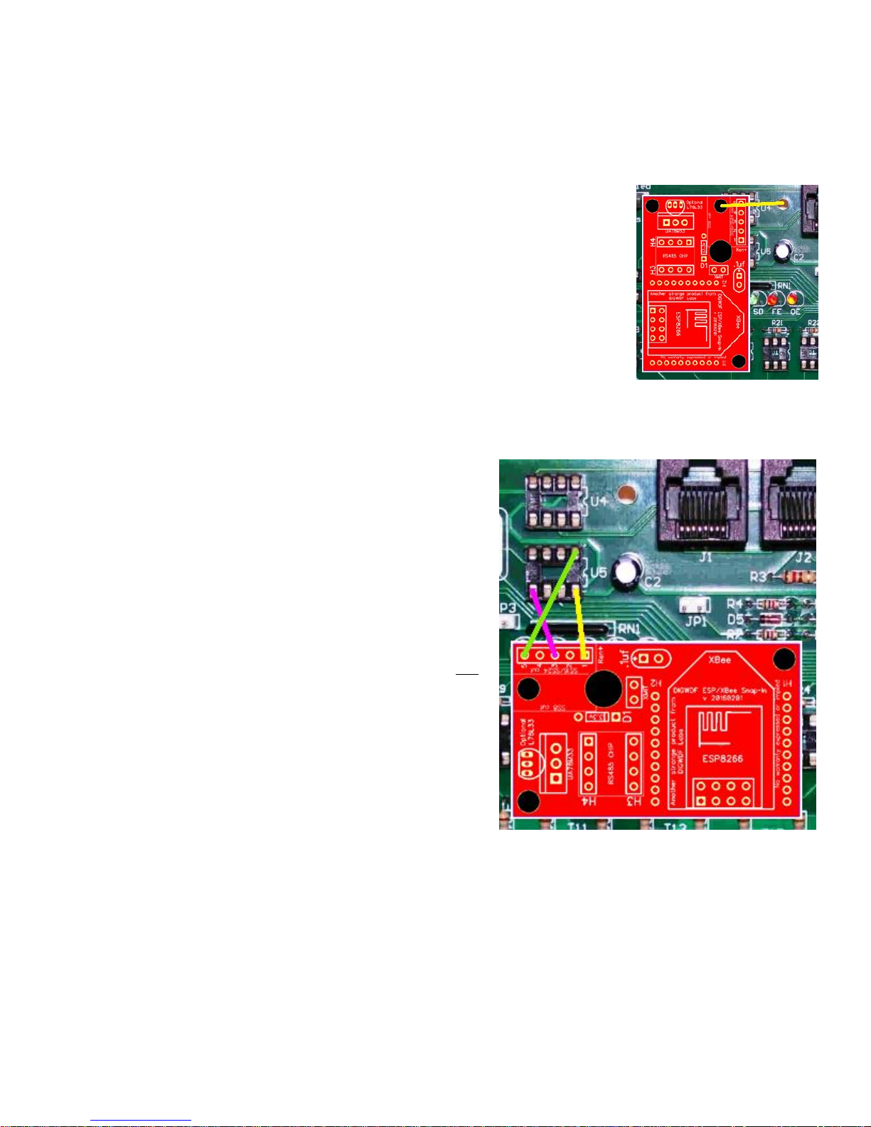
Using the Snap-In: SS8, SS16, SS24 on-board mounting
1. Carefully remove the U5 chip from the controller. P
2. position the adapter so that the two rows of 4 pins will fit into the U5 socket and gently
insert the adapter into the U5 socket so the header pins are firmly
seated in the socket.
3. On an SS24 controller, the mounting hole near the top of the adapter
PCB should be above a mounting hole next to the U4 chip on the
controller’s PCB. A small yet long screw with 3 nuts can be used to
mount the adapter firmly to the controller; then position the other
two nuts to support the adapter PCB at the right height and the top
nut to finish the mounting. (See photo to right.)
4. The SS8 and SS16 controllers do not have an extra mounting hole but
you can easily drill a 1/8” hole on your own. Verify the position for the
hole that it doesn’t hit any traces on the top or bottom of the PCB and
take your time.
Using the Snap-In: SS8, SS16, SS24 off-board mounting
1. Carefully remove the U5 chip from the controller
2. Mount the adapter elsewhere inside the
controller box.
3. Using individual connection wires, connect the
adapter’s pins to the U5 socket as shown in the
photo to the right: (strands of solid cat5 wire
work great for connecting wires). Consider that
you may decide to solder connection wires to the
bottom side of the board, using the
corresponding solder pads for the U5 socket.
4. Note: in this connection scenario, you should not
install the 1x4 stackable headers on the adapter.
DIGWDF XBee/ESP Snap-In Assembly & User Guide – v 20170308 -Page 5

Using the Snap-In with Renard-Plus controllers
1. Somewhere near the data input RJ45 jacks is a 5-pin
header, aptly named RenW Header, JP1, such as the
example to the right.
2. With a 1x5 female header installed on the BOTTOM of
the adapter’s PCB, simply plug the adapter into the
RenW header.
3. Note that no modifications need to be done to the
adapter’s PCB at all,
4. Note also that you should not install the 1x4 stackable
headers on the adapter and you do not need the 3.3
Zener diode or the XMIT header pins or shunt jumper.
5. The L78L33 regulator can be used with an XBee radio,
but the higher-capacity UA78M33 regulator is required
if you plan to use the ESP8266 module in place of an XBee.
6. If you plan to mount the adapter OFF the Renard-Plus controller instead of mounting it
directly onto the RenW header, use a 5-pin connection cable of suitable length to connect
pins 1-5 of the adapter to their corresponding pins on the RenW header.
Using the Snap-In with other controllers, Renard or otherwise
The adapter’s pin-out is highlighted in the picture to the right. Some comments:
Install the UA78M33 voltage regulator. Do not use the
L78L33 regulator.
Do not install the 1x4 stackable headers -- you won’t need
them and quite likely, the chip in the controller is not pinfor-pin compatible with what the snap-in needs.
If using the ESP8266 module, you do not need the 3.3
Zener diode, the 2-pin jumper and jumper shunt.
If using an XBee radio but you will not be transmitting
from the adapter, you do not need the 3.3 Zener diode, the
2-pin jumper and jumper shunt, either.
The data output from the adapter is at pin 5, TX data. This
is a +3.3v TTL output that should be connected to the
controller’s data input. It is TTL, not RS232 or RS485 so
you likely should connected it to the controller AFTER the
controller’s normal data input circuitry.
Connect the adapter’s pin 3 Ground to the controller’s DC ground.
Connect the adapter’s pin 1 +5vdc to +vdc somewhere on the controller. Note that while the
UA78M33 regulator is tolerant of voltages up to 30vdc and the LM1117T is tolerant up to
20vdc, the adapter generally does not need a heat sink to dissipate heat caused by high
voltage inputs and therefore, try to find a +5vdc connection. (Note: If the controller has only
DIGWDF XBee/ESP Snap-In Assembly & User Guide – v 20170308 -Page 6
3.3vdc available, bypass the voltage regulator by soldering a jumper wire across the
regulator’s pins 1 and 3.)
The pin 4 RX data connection is used ONLY when using the adapter as a standalone
transmitter and then only with an XBee radio. In a transmit mode, be sure to install the 3.3v
Zener diode, the 2-pin header and jumper shunt to protect the XBee radio’s input. (Note:
there is no facility or circuitry for transmitting via an ESP8266 module.)
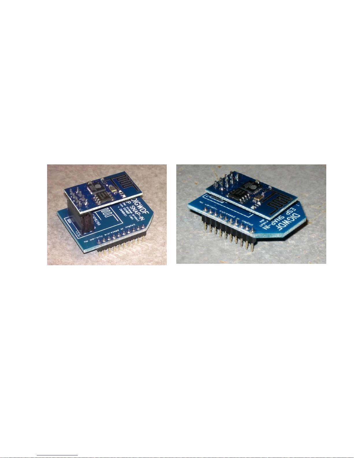
Using an ESP Snap-In adapter with the Snap-In
The DIGWDF ESP Snap-In was developed to plug directly into the two rows of female XBee headers
as a plug-in electrical replacement for an XBee radio with the understanding that the firmware and
network settings for ESP8266 operations are different and may require other firmware and/or
software modifications for successful operation. Note also that the ESP8266 module requires the
installation of the higher-current UA78M33 or LM1117T regulator in the XBee Snap-In.
DIGWDF XBee/ESP Snap-In Assembly & User Guide – v 20170308 -Page 7

Using the Snap-In as a transmitter (XBee Only)
The Snap-In works very well as a main transmitter in an XBee
network and can be powered directly from the computer’s USB
port. (Note: The ESP module cannot be used in transmit mode.)
Use an USB->TTL adapter at the computer, connecting it to
the Snap-In as follows:
o TTL +5v to Snap-In pin 1
o TTL GND to Snap-In pin 3
o TTL TX (data out) to Snap-In pin 4
o Install the 3.3 Zener, the 2-pin XMIT header and
the jumper shunt on the header. The 1x4 stackable
headers are not needed.
Radio Configuration
It is not possible to address all the possible radio-related configuration options in this user guide
for there is plenty of other documentation available about configuring XBee and ESP8266 modules.
Using an external power supply
An external 5vdc power supply or wall wart of adequate current capacity can be used to power the
adapter; be sure to connect the ground connection of the external supply to both the ground
connection of the adapter and the ground of the controller. As both the XBee radio and the ESP-01
module are 3.3vdc devices, you may alternately power the adapter with a 3.3vdc power supply in
lieu of either the UA78M33 or LM1117T regulators by soldering the power supply directly to the
snap-in at the appropriate pads where the voltage regulator would be.
Troubleshooting
If you make the proper connections to the controller, almost any other issues you might encounter
are either power-related (i.e. not enough voltage or current available to adequately power the
radio) or configuration issues with the radio’s wireless network which includes radio configuration
options, antenna orientation, distance from the transmitter, intervening obstacles, etc. – all things
that are well beyond the scope of this user guide.
Current requirements: an XBee radio in receive mode typically requires about 50ma of
current; in transmit mode, it can require upwards of 250ma of current. The XBee can also
function between 2.8-3.4 volts. The ESP8266 module requires about 230-250ma of current
all the time and is less tolerant of voltage variances. Make sure that the controller that is
being used to power the adapter can supply adequate power. Symptom of not enough
voltage or current: the radio will not be able to maintain solid communication with the
transmitter/network and the result is usually missed commands or an out-of-sync situation
or possibly total unresponsiveness.
Voltage testing:
o On the 5-pin header, the voltage between pins 1-3 should be 5vdc,
or close to it.
o The voltage between pins 2 and 3 of the UA78M33 regulator
should be 3.3vdc or close to it, regardless of which regulator is
installed. If the LM1117T regulator is used, the voltage between
DIGWDF XBee/ESP Snap-In Assembly & User Guide – v 20170308 -Page 8

pins 1 and 2 should be 3.3vdc or close to it. If the L78L33 regulator is used, the
voltage between pins 1 and 2 should be 2.9-3.3vdc.
o The L78L33 regulator is inadequate for powering the ESP8266 module or if using
the XBee Snap-In as a transmitter. It should be fine for an XBee radio in receive only
mode.
o If using the XBee radio, the voltage between pins 1 and 10 of the XBee radio should
be 2.9 – 3.3vdc.
o If using the ESP module, the voltage between pins 2 and either 3-5-7 should be
3.3vdc or close to it.
If it’s not working:
o Check soldering and voltages to make sure you don’t have an accidental short.
o If using an ESP module, ensure that the proper pair of circuit pads are soldered
together.
o The most common problem is that the radio is not configured properly, either at the
transmitter or at the receiver or both. Remember, XBee radios need IDENTICAL
settings while ESP modules need to work with your Wi-Fi router/access point.
o The second most common problem is that the PIC is not programmed properly. The
PIC and the radio of choice must be using the same baud rate.
o When using the ESP module, if you use start address firmware in the PIC and a also
in the ESP module’s setting, you could easily create an unworkable combination. We
suggest using the start address in one or the other, but not both – it’s too hard to
figure out what channels the controller is actually using if you use both.
o Be sure that the snap-in’s ground is connected to the controller’s ground.
o The plug-in option using the stackable headers that poke out the bottom of the PCB
applies ONLY to the SS8, SS16 and SS24 controller that uses either the ST485BN or
compatible chip in the U5 position. When plugging the snap-in into the U5 socket, be
sure that all 8 legs of the headers are plugged in – it’s easy to miss one or two and
possibly create a problem.
o Because the snap-in pirates electrical power from the controller board, it’s entirely
possible that the controller’s power supply doesn’t have enough extra current
available to power the snap-in. Remember, the LEAST amount of current necessary
is 50ma (XBee radio in receive mode) and the ESP module needs 230-250ma all the
time. If the controller is underpowered, the snap-in’s current requirements may
push it over the edge and make the controller behave erratically. If this is the case,
consider power the snap-in with an external wall wart, making sure to connect the
snap-in’s ground to the controller’s ground.
o Remember that XBees are limited to 57,600 baud communication speed.
DIGWDF XBee/ESP Snap-In Assembly & User Guide – v 20170308 -Page 9
 Loading...