

Page 1

FCD II & FCD 3
O p e r a t i n g m a n u a l
Table of contents
Safety rules .............................................................................. 3
1 Introduction............................................................................ 4
2 V ersions................................................................................4
2.1 Contents of packing (standard version) ...................................................5
3 Installation ............................................................................. 5
3.1 Electrical connection..............................................................................7
3.1.1 Flowmeter...................................................................... 7
3.1.2 Power supply ................................................................ 8
4 Preparation........................................................................... 8
4.1 Front panel.............................................................................................8
4.2 Keyboard................................................................................................9
4.3 Operation (FCD-II only) .........................................................................10
4.4 Working mode (FCD-II only) .................................................................10
4.5 Indicator of empty keg (FCD-II only)...................................................... 11
4.6 Master key (FCD-II only) ...................................................................... 11
4.7 Host mode (FCD-II only) ....................................................................... 11
4.7.1 Programming litre calibration (FCD-II only) .............. 12
4.7.2 Programming the portion size (FCD-II only) ............. 12
4.8 Setting to zero (FCD-II only) ................................................................. 13
4.9 Re-calibration (FCD-II only)...................................................................13
4.10 Cleaner key (FCD-II only).................................................................... 14
Digmesa AG, Keltenstrasse 31, CH-2563 Ipsach / Switzerland
Phone +41 (32) 332 77 77, Fax +41 (32) 332 77 88
Bedienungsanleitung FCD 3 823-1001_GB / Mai 2005
www.digmesa.com
Page 1
Page 2

4.1 1 Clock setting (FCD-II only) ..................................................................14
4.12 Date setting (FCD-II only) ...................................................................14
5 T roubleshooting................................................................... 15
6 S pecifications*.................................................................... 16
7 Appendix............................................................................. 17
7.1 Assembling an extra module ...............................................................17
7.2 How to change a module ......................................................................1 8
7.3 Location of the fuse ..............................................................................18
Software addition FCD-III ............................................................................19
1 General Operation ................................................................................... 19
2 Cleaning (CLEAN-Dallskey)..................................................................... 20
3 HOST - Mode (Master-Dallskey).............................................................. 20
4 Counters / resetting counters ..................................................................20
5 Calibration...............................................................................................21
6 Parameter settings..................................................................................22
7 Date settings...........................................................................................22
8 Data inquiry via interface .........................................................................22
The user is not entitled to indemnities for possible technical imprecisions or
misprints present in this manual.
This manual may be modified without forewarn.
Page 2
Page 3

Safety rules
1. Read throught the instructions before you put the FCD-II into
operation. Follow all the operations according exactly to the directions
for use.
2. Keep to the directions for use and to the indications that may appear
on the FCD-II.
3. Cut off power supply before opening the connection cover or
unscrewing the front panel.
4. The FCD-II is protected according to the safety rules IP65, i.e. it is
protected against sprays of water , but only if the transparent cover is
closed.
5. The voltage must agree with the values written on the label on the
back.
6. The FCD-II is provided with a terminal for the earthwire. The
grounding must be absolutely connected.
7. The FCD-II should not be put into operation without the connection
cover (danger of wounding if the electronics is touched).
8. Cut off power supply and call a technician if one of the following
cases occurs:
- if water or other fluids have entered the FCD-II.
- the FCD-II doesn’t work correctly even though you have followed all
the instructions given. Do not try to change anything on your own;
do not press any key trying to get some reaction.
- if the FCD-II falls down and the box is damaged.
Page 3
Page 4

1 Introduction
The FCD-II is a precise control system with the most modern
microprocessors.
The quantity of fluids, that passes throught the installation is constantly
measured. Bar keepers don’t have to change their habits: the FCD-II corrects
the intertias present inside the flowmeter automatically .
The FCD-II has several counters that can be questioned at any time. Each
pipe can be calibrated precisely according to its use (i.e. according to the
drinks that have to be measured: beer , mineral water, pre-mix, etc...).
The access to special functions on the flow computer FCD-II is possible only
by using intelligent keys.
The FCD-II signals whenever a keg is empty by using a flowmeter provided
with foam detection. Also in the standard version a relay is avalaible with
which further alarm systems can be connected.
2 Versions
The FCD-II is avalaible in the following versions:
- control of four pipes, art. no 923-9104 (standard version)
- control of eight pipes, art. no 923-9108
- control of twelve pipes, art. no 923-91 12
- control of sixteen pipes, art. no 923-91 16
The FCD-II can be equipped with additional modules. Four additional pipes
per modules can be added. The FCD-II can contain no more than four
modules (i.e. 16 pipes).
Page 4
Page 5
2.1 Contents of packing (standard version)
- 1 FCD-II
- 2 cable inlets PG1 1 (art. no 699-0003)
- one for the power supply cable 230V ( 3 wires with min. section of
2
0.75mm
- one for four flowmeter cables (external diameter max. 4mm).
- 1 cable inlet PG9 (art. no 699-0002) used for the cable of the serial
interface RS-485.
- 1 intelligent key with the black ring (master key) art. no 990-0002
- 1 intelligent key with the silver ring (cleaner key) art. no. 990-0000
- 1 manual art. no 823-1001
and external diameter 6.80mm)
3 Installation
Choose a suitable place for the FCD-II and keep to the following instructions:
- the unit has to be easily reached.
- the unit has to be put at a comfortable height.
- the place has to be well illuminated (the display has no rear light)
Choose whether to install the cable inlets on the rear side or on the bottom
side of the FCD-II box.
Bottom side
Page 5
Page 6

rear side
Cut out as many holes as you need on the side chosen by using a
screwdriver and a hammer . T ake one of the cable inlet s PG-1 1 in order to
connect the first group of the four flowmeters. Unscrew the nut and put the
screw into the corresponding hole and fix it. Then install the second cable
inlet PG-1 1 for the 230 V cable. If you need an interface, install the cable inlet
PG-9 as well.
Place the FCD-II as follows:
Fix a screw into the wall and hang the FCD-II on it. Open the connection
cover . For additional safety of the unit, two more screws can be fixed on its
corners.
Page 6
Page 7
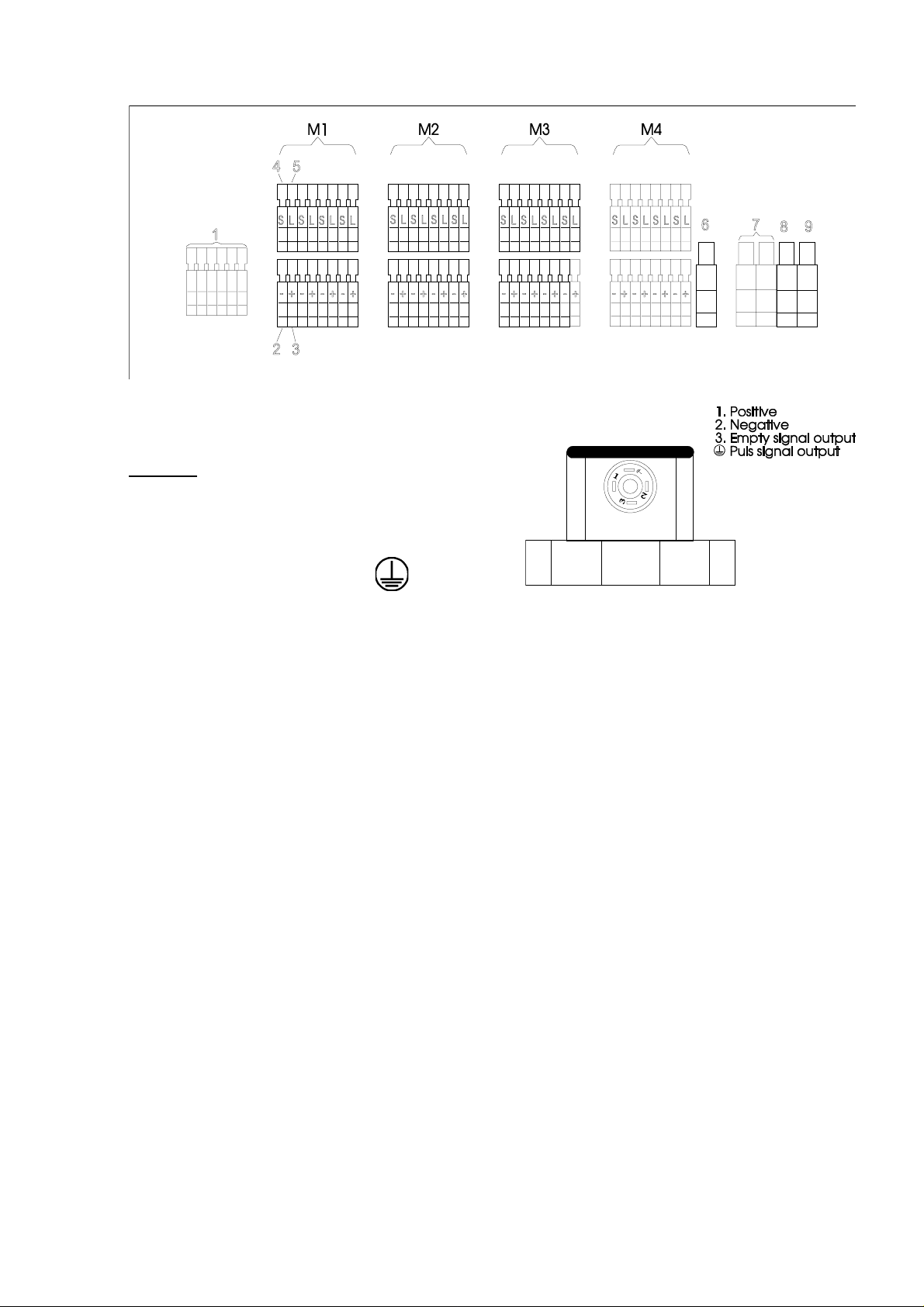
3.1 Electrical connection
diagram connection
Legend
1 = serial interface RS-485
2 = negative pole "-" on Flowmeter 2
3 = positive pole "+" on Flowmeter 1
4 = signal on Flowmeter
5 = empty keg indicator on Flowmeter 3
6 = connection for a flowmeter group
7 = earthing
8 = additional relay connection for empty keg indicator
9 = power supply neutral
10 = power supply phase
3.1.1 Flowmeter
Number progressively each cable of the flowmeters which will be connected
to the FCD-II. Insert the cable of the first flowmeter into the corresponding
cable inlet. Take off the cable insulation for about 5 cm and strip each wire
(about 5mm).
Put each wire of the first flowmeter into the terminal as follows:
Press the white lever by using a small screwdriver (no 0 or no 1). At the same
time, insert the wire into the terminal. Release the lever.
Connect the flowmeter wires as follows:
Page 7
Page 8

- green wire = terminal „-“ on Flowmeter 2
- brown wire = terminal „+“ on Flowmeter 1
- white wire = terminal „S“ (signal)
- yellow wire* = terminal „L“ (empty keg indicator) on Flowmeter 3
*Not all flowmeter models dispose of a foam indicator .
Repeat this operation for each flowmeter .
Note: the wire colours listed above are a DIGMESA-code and can be
changed.
3.1.2 Power supply
Insert the 230V cable ( a 3-pole cable with a section of 1,5mm2 is
recommended) into the cable inlet. Take off the cable insulation for about 5
cm and strip each wire (about 5mm).
Connect each wire as follows:
Phase = orange terminal
Neutral = blue terminal
earthing = green terminal
Close the connection cover , connect the flowmeters and turn power on.
4 Preparation
Before operating the FCD-II, note that:
- Text written in italics represents a message on the display.
- Text written in bold refers to the keyboard.
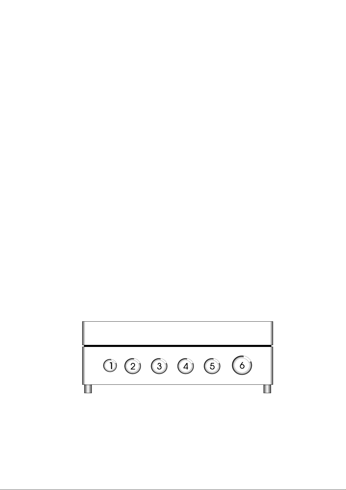
4.1 Front panel
1. LED indicator (empty keg indicator).
2. LCD display
3. Keyboard
4. intelligent key socket
5. Connection cover
Page 8
Page 9

4.2 Keyboard
to the previous line
to the next line
confirm entry
entering the values in programming mode
program/examine the portion size
program/examine litre calibration
setting to zero
go to programming mode
Page 9
Page 10

4.3 Operation
NOTE FOR FCD-III USERS : the following chapters (4.3 to 4.12) are only
valid for FCD-II. Please go to page 19 'Software addition for FCD-III' !
As soon as the tension is connected, FCD-2 will appear on the display . If no
button is pressed for about one minute, the clock will appear on display .
4.4 Working mode
Any lines can be reached by pressing <- or ->. The display will show
automatically the first line just after the selection of the last one. The number
of lines connected to the unit can be controlled as well.
As soon as the requested line is displayed, press the Enter button. The unit
will show either nodEF (not defined) if the line is not programmed yet, or it
will show the quantity in litres or in portions.
At the very bottom of the display it will be indicated whether the quantity is
expressed in litres or in portions. There are two different litre counters:
Litre flag flashes = shows the quantity poured out of the connected keg.
This counter can be set to zero by pressing the RESET
button at any time without the master key (intermediate
counter).
Litre flag normal = shows the quantity poured out of the line. This counter
can be set to zero only by pressing the RESET button
using the master key . (global counter)
Portion flag = shows the number of portions poured out. This counter
can be set to zero only by pressing the RESET button
using the master key.
By pressing the ENTER button, you can go to the next counter . The FCD-II
displays per line only what is programmed. Examples:
- If nothing is programmed in the correspondent line, nodEF will appear on
the display.
- If it is programmed only in portions, only the portion counter will appear .
- If only the liter calibration is programmed, only the two-litre counters will
appear .
- if both values are programmed, the counters will appear in this order:
intermediate counter , portion counter, global counter .
Page 10
Page 11

4.5 Indicator of empty keg
As soon as the signal „no more fluid in the line“ comes from the connected
flowmeter (which must have four pins), the red LED (1) lights up on the FCDII. When the unit is in standby mode (it displays the clock), the
correspondent line number will be displayed as AL-XX where XX represents
the line number.
If you are working on the FCD-II and the LED lights up, it means that one or
more kegs are empty . You can finish up normally . Now reach one line after
another by pressing the arrow buttons. The lines which are empty will appear
and begin to flash.
Y ou can also use the additional relay connection to drive an external alarm
(for ex.: a lamp, a horn, etc... ).
4.6 Master key
When the master key is put on its socket for the first time, you will hear
three beeps and the message HOSt will appear on the display. From now on,
you will hear only one beep when you put the master key .
Only one master key per FCD-II is valable. If the master key of the FCD-II
gets lost, another one can be bought. As soon as the new key is put on the
socket, only this one will be right for this unit.
As long as the master key remains on the socket, you have access to all
features of the unit:
- setting all the counters to zero.
- programmation of the litre and the portion calibration.
- continuous flow monitoring.
All lines have to be programmed before FCD-II is ready to work. Otherwise,
some errors in the data can occur .
4.7 Host mode
Put the master key on the socket to enter the host mode. The FCD-II has
two calibration values per lines: one for litres and one for portions.
Page 11
Page 12

4.7.1 Programming litre calibration
Choose one line by using the arrow button. Then press the PROG button.
Now the number of pulses per litre is displayed (max 32,766 pulses/litre)
depending on the flowmeter mounted in the pipe (for ex.: FFB-50 = about 240
pulses/litre; FFC-40 = about 335 pulses/litre). Y ou can programm this value
in two ways:
1st possibility
Modify directly the value. Press the RESET button, in ordre to set this value
to 00000. By using the arrow buttons, you can choose the digit that you want
to change (the chosen digit flashes). The digit can be changed by pressing
the + button. Number 0 appears after number 9. If the + button is pressed
continuously , the digit will change its value automatically. Release the button
as soon as the requested number is reached. Press the ENTER button to
confirm. The display will show the line number which has been programmed.
2nd possibility
The FCD-II can be programmed even when the number of pulses is not
known. When the number of pulses is displayed, press LITER and then
PROG. A little horizontal dash appears on the display. Any quantity of liquid
(at least 0.5 l. ) can now be poured out of the tap. Meanwhile the little dash
moves. When the requested quantity is poured out, press ENTER. By
pressing the + button and the arrow keys set the poured quantity in litres (for
ex.: 00.760). Press ENTER to confirm otherwise press the PROG button to
start again. Press the LITER button to check up the litre calibration. The
pulse/litre measured appears on the display for two seconds.
4.7.2 Programming the portion size
To program the portion size, it is important to consider that:
If the litre calibration is set to zero, the portion size can not be given in litre
but only in pulses.
1st possibility (litre cal. = 00000)
Choose one line. Press PROG and then PORTION. By pressing the arrows
and the + button set the number of pulses which correspond to the requested
portion. Press ENTER to confirm.
2nd possibility (litre cal. is set)
Page 12
Page 13

Choose one line. Press PROG and then PORTION. By pressing the arrows
and the + button set the portion size in litres (for ex.: 00.300 = 3dl = 300ml).
Press ENTER to confirm.
3rd possibility (litre cal. = 00000)
Choose one line. Press PROG and then PORTION and then PROG again. A
little horizontal dash will appear on the display . Now pour the requested
portion out of the tap. Meanwile the little dash moves. As soon as the portion
is poured out, press ENTER to confirm. The measured number of pulses
appears on the display . If everything is all right, press ENTER to confirm,
otherwise press PROG and start again.
4th possibility (litre cal. is set)
Choose one line. Press PROG, then PORTION and then PROG again. A little
horizontal dash will appear on the display . Now pour the requested portion
out of the tap. Meanwile the little dash moves. As soon as the portion is
poured out, press ENTER to confirm. The measured portion in litres appears
on the display . If everything is all right, press ENTER to confirm. If the
requested quantity is not exact, it can be corrected by using the keyboard
(for ex.: poured quantity = 00.276 real portion size=00.300).
Note: the reference of the FCD-II is pulses. When the portion size is given in
litre, the FCD-II will approximate this value according to the litre calibration.
Example: Litre calibration = 24 4
Portion size = 00.300 litre
Portion pulses = 244 x 0.3 = 73.2
reference number = 73
rounded portion size = 73 : 244 = 00.299
Once the programmation of every line is completed, take out the key .
4.8 Setting to zero
Put the master key on the socket and choose a line using the arrows. Once
reached the requested line, press the ENTER button. Go to the requested
counter by pressing the ENTER button. By pressing RESET, the value will be
cleared to zero. After setting all the requested lines to zero, t ake out the key.
4.9 Re-calibration
Page 13
Page 14

If, for example, a 50-litre keg is emptied but the value on the display does not
correspond (for ex.: 47 litres), this value can be corrected as follows:
- choose the requested line by using the arrow buttons.
- press the PROG button and then the LITER button: the display will show
the global counter (litre counter).
- correct this value to the actual one by using the + button and the arrows
- press ENTER to confirm.
4.10 Cleaner key
The FCD-II has a special function to clean the pipes. Put the cleaner key on
the socket, you will hear two consecutive beeps and CLEAN will appear on
the display . The key has to be kept on the socket during the entire cleaning
and will be taken away at the end of it. The counters do not change during
the cleaning.
4.1 1 Clock setting
Clock setting is possible only if the FCD-II is in standby mode. Press the
PROG button first, the minute indicator flashes. Keep pressing the + button
as long as you reach the right number . By pressing the arrow button, you can
reach the hour indicator . Set the hour by pressing the + button. Press
ENTER to confirm.
4.12 Date setting
Put the master key on the socket and wait until the FCD-II go into the
standby mode (about 1 minute). Press the PROG button first, the minute
indicator flashes. Press the ENTER button if you want to bypass the clock
setting. The year will be shown. You can modify it by pressing the arrow and
the + buttons. Press the ENTER button to confirm. Mt (= month) and Dt
(=date) will appear consecutively on the display . You can modify these values
by pressing the + button. Press ENTER to confirm each one. Then the clock
will appear on the display . Take out the master key .
Page 14
Page 15

5 Troubleshooting
The indicator is empty
a) check the power supply
b) check the connection between the main and the front print
c) check the fuse (see schema 7.3.)
d) call a technician
A flowmeter group does not work
a) check the cables of each flowmeter (reversed polarity)
The empty keg indicator flashes without reason
a) exchange the wire of the signal indicator with that of the empty keg
indicator
The display shows incomprehensible values
a) cut off power supply for 10 seconds
b) call a technician
Page 15
Page 16

6 Specifications*
Power requirement : 230V~ / +/- 10% 50-60Hz
(1 15 V~ 50-60Hz at request)
Power consumption: max 5 Watt charged with 16 flowmeters
T emperature tolerance
operating: -10°C to +70°C
storage: -20°C to +70°C
Measure functions: 3 pulse counters per line (32 bits)
Display functions
intermediate counter: 0.01 to 99,999 litres with automatic range
selection
global counter: 0.1 to 99,999 litres with automatic range
selection
portion counter: 1 to 99,999 portions
Display: 5 digits LCD display
Keyboard: 10-key keyboard
Memory: Battery backed-up memory (10 years)
Flowmeters: All the DIGMESA flowmeters. The Sm
flowmeters (4 pins) are specially suitable to
work with the FCD-II. It permits to monitor
the empty kegs.
Inputs : 16 flowmeter inputs divided into four
modules.
Outputs: one relay contact max. 6Amps / 230V~
Interface: 1 RS-485 interface.
*technical modification rights reserved.
Page 16
Page 17

7 Appendix
7.1 Assembling an extra module
When you order an extra module to monitor four extra flowmeter lines, the
package will contain:
- 1 cable inlet PG 1 1, for 4 flowmeter cables ( 4mm diameter).
- 1 module
Follow the procedure below to mount the module on the FCD-II.
- cut off power supply .
- unscrew the connection cover .
- assemble the cable inlet as described in § 3.
- connect the cables with the FCD-II (§ 3.1.1.)
- unscrew the front panel.
- take out carefully the plug from the front print.
- put the module on the next free 30-pole socket which corresponds to the
flowmeter group. Press the module down and turn until it remains fixed
vertically .
Page 17
Page 18

- connect the plug with the front print again.
- fasten the front panel.
- fasten the connection cover .
- turn power on.
- go throught every line by using the arrow keys. Check if the new module is
recognized. If everything is all right, the new 4 lines will appear on the
display.
7.2 How to change a module
Open gently both lockings which are located at the extremities of the
connector , turn the module down and take it away .
7.3 Location of the fuse
legend
a = module 1 (flowmeter 1 to 4)
b = module 2 (flowmeter 5 to 8)
c = module 3 (flowmeter 9 to 12)
d = module 4 (flowmeter 13 to 16)
s = fuse holder
Page 18
Page 19

SOFTWARE FCD-III
Addition of the operating instructions FCD-II
In the context of the technical progress our FCD-II received a more modern microprocessor
as well as a completely new designed system software. Since in terms of hardware for the user
did not change anything, the past manual of FCD II keeps its validity.
What has changed, is the operation of the equipment. This is described in detail in this
appendix to the FCD-II manual. Furthermore, the data exchange protocol has also changed.
You experience more information in addition in chapter 8 of this auxiliary documentation.
1 General operation
After switching on the power, the device announces itself with display and sound check; and thereafter it will
display the installed
you can
restart
The display shows alternating the selected line number and the corresponding counter reading. If is
displayed in place of a value, then this value is greater than and cannot be displayed. Big values can only
be accessed via the serial interface. Internally, the range is limited to 4294967295 impulses, that means,
a flowmeter with a calibration value of 240 Imp/Lt. will count up to 17,9 mill. litres and then will continue at zero.
version number
for a certain time. To get the version number from already running device,
the device by pressing simultaneously the keys
+
Enter
+
Reset
LED
As function control, the
blinks periodically briefly . If a data communication takes place, then this flickers
during the time of the data communication; simultaneous a gnashy noise is to be heard. This serves for the
simplified error tracing in case of difficulties during the data communication .
If you use
measuring instruments with integrated empty detection
, thus the LED goes into steady light as soon
as one of the attached measuring instruments is empty . At the same time, the display changes on the
corresponding line to alternating: > > (example : Line 3 Alert). If at least one of the
lines is empty, then also the relay is switching with a defined debounce time (
With the keys you
Liter
With you alternate the display between
With the key the
Portion
portioncounter
selected counter announcement. The
You can
adjust the time
(not however the date) without masterkey : change on time indication and press
select the line
is indicated. The key alternates between
date
(the minutes blinks now), then adjust the value with and change between minutes and hours
with or . Terminate with .
If the parameter settings allows, you can
which will be indicated.
totalcounter
LITER
( ) and
Enter
is periodically represented during time indication as scrolling text.
+
Enter
reset the splitcounters
without masterkey :
change to the desired line and make sure that the splitcounter is displayed ( flashing).
If it's allowed, the display will show ' ' by pressing the key . After 4 seconds of continuous
Reset
Conn. AUX
splitcounter
LITER
- closing contact).
LITER
( flashing).
time indication
and the
Prog
actuation, the splitcounter of the selected line will be set to zero with acoustic acknowledgement.
For this, you receive more information in chapters 4 and 6.
Page 19
Page 20

2 Cleaning (CLEAN-Dallaskey)
At an FCD, as many as desired
However,
additional
cleaning keys with
cleaning keys
individual key numbers
can be used ; one is delivered in each case.
can be ordered at any time.
Simply apply the cleankey to the support plate and the display announces ' ' blinking. After some seconds,
the unit beep's twice and the flashing announcement change to statically. Starting from this time, the cleaning
is activated and registered in the internal
portion counters are suppressed. Each line is documented with its own
cleaning diary
. For the duration of the cleaning process, litres- and
cleaning counter
, how many litres
actually flowed through with the respective cleaning. If the cleaning key is removed, the announcement changes
again to blinking; after a few seconds, a threefold beep appears and the display change into the normal mode;
the cleaning is terminated. The ten last cleanings are stored internally constantly and are, if necessary,
accessible via the serial interface
(starting time, stop time, keynumber, quantities).
3 HOST - Mode (MASTER-Dallaskey)
For all further functions than the already described you must change first into the
Set for this the provided
can
be used only at it's associated device
MASTER Dallaskey
on the support plate. This keys are
. Thus pay attention if you operate several FCD's in your installation.
Newly delivered keys are not assigned yet. By putting the key the first time on, the device recognizes a
automatically and assigns it themselves irrevocable .
Master keys possibly
assigned in former times
are defined thereby as
to be invalidly
Once assigned to a certain FCD, the master key cannot be made valid for another FCD, except it will be
sent back to DIGMESA for reinitialization.
If you put a
beep
moment : ' '. If the key is
new key
. If the key is
on the first time, then the FCD will acknowledge this after a few seconds with a
already assigned to this FCD
already assigned to another FCD
, then a
unique beep
, then nothing happens (invalid key).
appears. The display shows for one
host mode
individual
from now on.
.
, i.e. a master key
new key
threefold
4 Counters / resetting counters
The FCD's have by default
- 1 : Totalcounter (editable) - 2 : Splitcounter (editable)
- 3 : Portioncounter (editable) - 4 : Cleningcounter (not editable)
Counters 1, 2 and 4 contains a common
his own factor possess. You can use it as freely calibratable portion counter like also for indicating
consumption in another unit (gallones(US/GB)Quart etc.) or for example a price, so that the computational
amount can be read out directly without converting, as portion counter : E.G. 1 litre product corresponds
to 224 impulses per litre - 1 litre costs 3,45$ = (224: 3,45) 65 impulses per $.
Counters 1 and 3 can be resetted only in the host mode, while for counter 2 (splitcounter) it can be
intended whether he may be resetted without masterkey or not. (see chapter 1 and 6)
Counter 4 serves for the documentation in the cleaning diary and is not influenceable.
Resetting counters in the HOST-Mode :
Put on the Masterkey, then select first the desired line with
Splitcounter : hold for 4 seconds
Totalcounter : hold and for 4 seconds
Portioncounter : hold and for 4 seconds
The procedure is acoustically acknowledged.
four counters each line
calibration factor
Reset
Reset
Reset
Liter
Portion
; three are directly editable:
(pulses per unit) during counter 3 (portions)
Page 20
Page 21

5 Calibration (HOST Mode only)
Flowmeters delivers differently amounts of
impulses per litre
; dependent mainly on the
nozzle size
and the
of the measured medium . Therefore it is necessary to calibrate all lines before the operation.
Different methods are to you at the disposal. If you already know the number of delivered impulses per litre,
then you can use the
Press the keys or at the same time, depending whether you would like to calibrate
a litre or a portion.
manual calibration
Prog Liter
+
Ex factory preset
: put on the masterkey and select the desired line with and .
Prog
Portion
+
, the display shows now or the last adjusted value.
With the keys you select the decimal place which can be edited (this blinks) and with the key
you adjust their value. Terminate and assume the value with .
Breaking off
NOTICE :
a begun calibration is at any time possible
A change of the calibration affects immediately the counter reading, since
Enter
by removing the masterkey
.
the actual impulses
and not
the calibrated quantities are cumulated internally!
Automatic Calibration :
and press 4 seconds . The display indicates : . ('A' blinking)
NOTICE :
An automatic calibration procedure sets previous the respective total counter to zero, not however the
begin as with manual calibration until the display shows the actual calibration value
Reset
other counters. The taken quantity per procedure is credited thereafter to all counters of this line.
viscosity
+
There are
two measuring possibilities
The display shows the number of measured impulses. Terminate and assume the adjustment with .
In addition, you can do
2:
extract
a measuring beaker. In place of ENTER you press . The display will show now ; with and
available; 1: You ext ra c t
any quantity
into a tared container and this thereafter
Prog
exactly 1 litre
product into a measuring beaker.
Enter
weigh
or filling partly
+
you have to change the value in accordance with the level of the measuring beaker or the weight in kilograms.
The
1:1 input of kilograms
For products with strikingly
in accordance with their
works satisfactorily with
different density
specific weight
than water (oils, etc..)
.
most usual beverages
converting
.
into litres is however recommended
NOTICE
that,
as larger as the calibrated quantity is
In order to obtain a
NOTICE
that a recalibration always is oriented at the counter reading of the total counter. As example for a
very exact calibration value
, as
more exact the long-term measurement
, you have the possibility of a
recalibration
will be.
.
successful recalibration we make use of a keg beer with 30 litres contents : attach the absolutely new keg
and set the total counter to zero. If the keg becomes empty, re-elect and thereafter
press 4 seconds
value ( ) with and .Terminate and assume the value with . You can use
Prog
.
The display shows now the value measured so far, e.g. . Adjust now the correct
+
Prog Liter
+
Enter
this feature also from the beginning of initial operation, since with the automatic calibration, the total counter
will be set to zero and the extracted quantity from calibration is already credited to the total counter. You must
start thus only with a new container .
Page 21
Page 22

6 Parameter settings (HOST Mode only)
The FCD-III software contains 3 operating parameters since version 1.00, which are described in the following.
Possibly newly added parameters on higher OS-Versions will be separately documented.
The fundamental editing steps itself will remain the same however : change into HOST-Mode (Masterkey) and
Prog
press for 4 seconds. With the keys you can choose the desired parameter, with the key
you can change it's value and with the key you quit the parameter-editing mode. Note, that in this mode
Enter
+
an abort is not possible by removing the master key; changes are directly valid.
The parameters and their effects are :
date & timemode : european / american
automatic summertime : yes / no
reset of splitcounter allowed without masterkey : yes / no
7 Date setting (HOST Mode only)
The FCD-III software contains an extensive time and date system. It is appropriate for the use in Europe
as well as for the American continent. The display changes as follows :
European : 24 hours, TT/MM/JJJJ American : 12 housr AM:PM, MM/DD/YYYY
The leap year compensation happens automatically. Further it can be adjusted whether an automatic
summer- wintertime compensation is to take place or not. This happens depending upon time zone
NOTE
adjustment (EU/US) at the respective fixed dates.
during spanning date adjustment, the time will automatically adjusts without further inquiry.
Thus during setting up, first adjust of the date and afterwards of the correct time.
(Parametersettings see chapter 6; time settings chapter 1)
that with activated summer time compensation
+
Enter
Enter
Enter
Enter
Date setting : put on the masterkey and press , the display shows now the year.
Edit the year with the keys , or ; terminate with . The display shows : (month)
Edit the month the same way like the year and terminate with . The display shows : (date).
Edit the date the same way and terminate with . The date setting is now completed.
8 Data inquiry via interface
The FCD's have alternatively a RS-232 or a RS-485 interface (has to be indicated at the order)
with the objective to exchange datas with an superordinate device. If only one FCD shall to be
connected to another device (PC, countersystem etc.), RS-232 is the best solution, since no peripheral
interface adapter is needed. However, if several FCD's have to communicate at a single connection,
then RS-485 is obligatory. In this case, each FCD must be configured with an unique device number,
which is adjustable via jumpers. Details for this see in the main manual to FCD-II.
The protocol of FCD-III
is no longer compatible
can be made compatible without larger expenditures. Detailed documents and support to this you will
receive upon request by our development department.
Upon demand, there is also a Windows PC software available, with which the FCD III's can be read out
and get configured easily. This contains also an export function to transfer datas into free configurable
cell's in an EXCEL table.
to the protocol of FCD-II. However, existing software
Page 22
Page 23

Page 23
Page 24

Digmesa AG, Keltenstrasse 31, CH-2563 Ipsach / Switzerland
Phone +41 (32) 332 77 77, Fax +41 (32) 332 77 88
www.digmesa.com
Page 24
Bedienungsanleitung FCD 3 823-1001_GB / Mai 2005
 Loading...