

Page 1
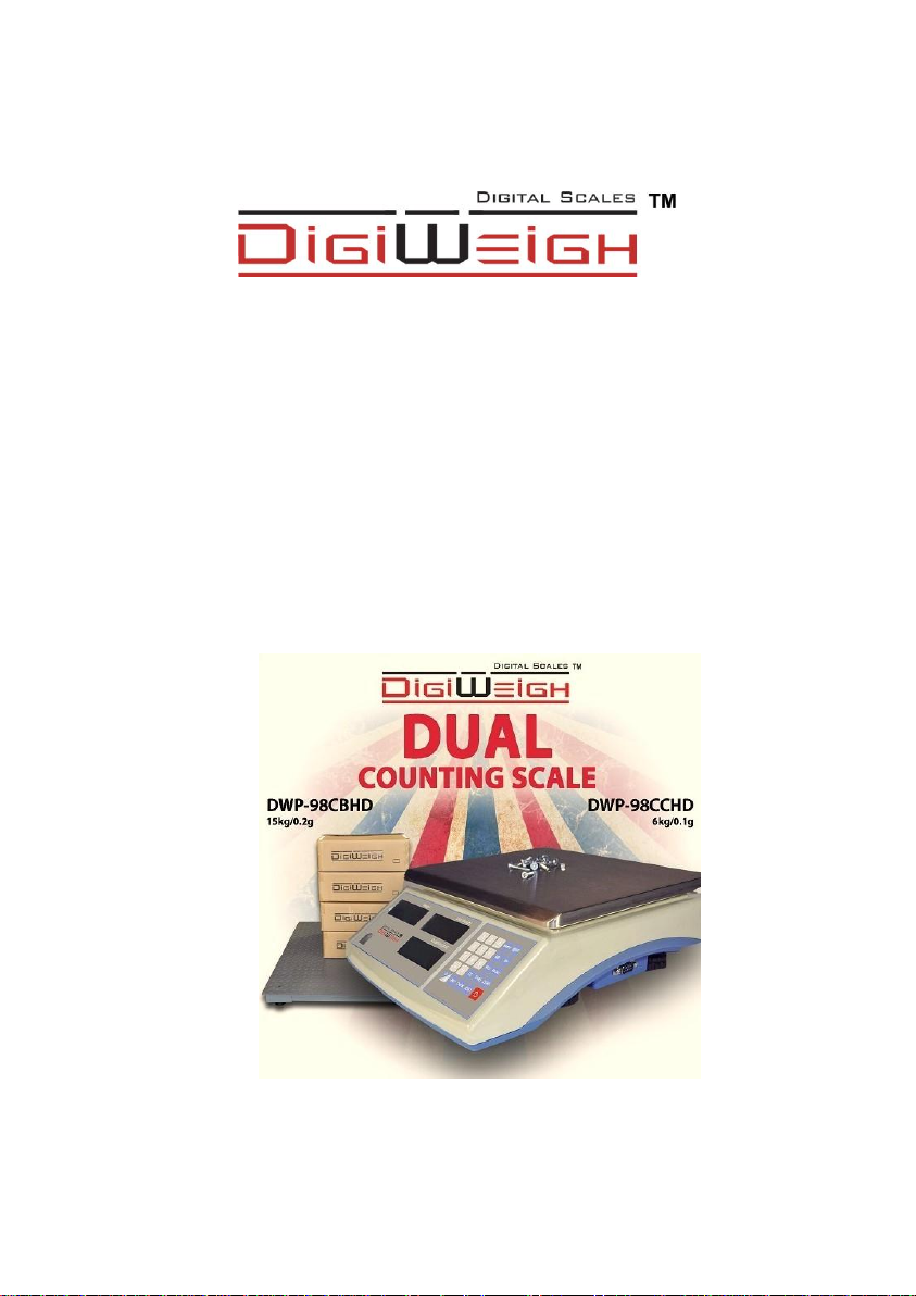
DWP-98D Dual scale
User’s Guide
PLEASE READ THIS MANUAL VERY CAREFULLY BEFORE
ATTEMPT TO OPERATE THE INSTRUMENT
Specifications subject to change without prior notice
Page 2

CONTENTS
1. INSTALLATION
2. SPECIFICATIONS
3. KEYS, DISPLAY AND CONNECTIONS
4. GETTING STARTED
5. INITIAL SETUP
6. INSTRUCTION FOR USE
7. RS232 DATA OUTPUT
8. BATTERY POWER AND RECHARGING
9. ERROR CODES
10. DAILY CARE AND MAINTENANCE
Page 3

1. INSTALLATION
Because of metrological legislation, installation/some
metrological parameter settings are limited to be done by
authorized personnel only. Do not attempt to change any of the
built-in metrological parameters. Contact your dealer for more
information and technical assistance.
CAUTION:
The instrument is legal for trade only when it is sealed (and/or
stamped) and bearing a serial number. Do not attempt to break
the seal (or stamp) affixed to the instrument or remove the
serial number. Contact your dealer for more information and
after sales service.
To ensure performance accuracy, do not use the instrument in
where or when the environment condition falls beyond as those
listed on SPECIFICATIONS.
Do not attempt to open the instrument, no user serviceable
parts inside.
Page 4
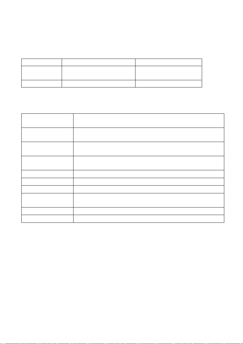
2. SPECIFICATIONS
Stabilization
time
2 second typical
Operating
temperature
0°C - 40°C / 32°F - 104°F
Power supply
220~240V AC (110V optional) 50/60Hz
built-in rechargeable battery 6V4AH.
Display
3 windows 6 digits 0.8’LCD display.
and 11 status indication
Zero range
0mV~8mV
Housing
ABS housing and Stainless steel pan(230*290mm)
ADC
Σ-Δ
External
Resolution
1/60000
PLU
100
Interface
RS-232 Output(second RS232 and RS485 optional)
Model#
DWP-98CCHD
DWP-98CBHD
Max
Capacity
6kg
15kg
Readability
0.1g
0.2g
2.1 GENERAL SPECIFICATIONS
DWP-98D Series(resolution 1:60000; unit :kg,lb,g)
Common Specification
Page 5
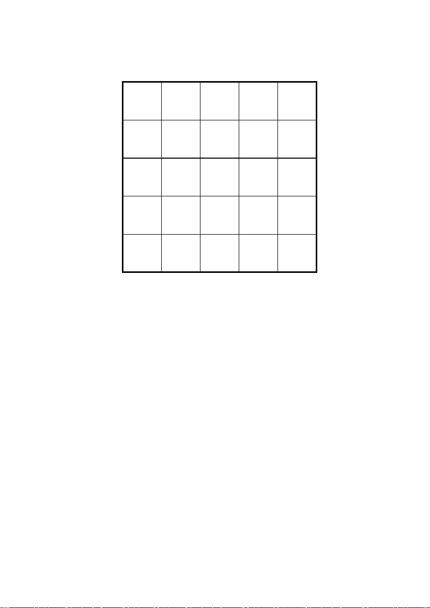
3. KEYS, DISPLAY AND CONNECTIONS
ON/
OFF
#SETCHECKUNIT
ZEROTARECE0.
RECALLPLU987
M+MR654
@WTSAMPLE321
ON/
OFF
#SETCHECKUNIT
ZEROTARECE0.
RECALLPLU987
M+MR654
@WTSAMPLE321
①/②
1.ON/OFF
Power on /off the indicator
2. UNIT PIECE WEIGHT SET KEY (@WT)
Press this key to confirm the unit piece weight entered by numeric keys.
3. WEIGHT UNIT KEY
Press this key to shift among various weight units.
4. M+ KEY
Press this key to accumulate the current quantity to memory
Press this key to print out the result
Press this key as next parameter when setting
5. MR KEY
Press this key to read the accumulate result
6. TARE KEY
Press this key to tare off the weight of a container.
Press this key to enter parameter setting when count down
or confirm and save parameter when setting;
Page 6

Press this key to confirm the preset-tare by numeric keys
7 SAMPLE QUANTITY SET KEY
Press this key to confirm the sample size (pieces) entered by numeric keys.
8. CHECK KEY
Press this key to set upper & lower quantity check limit and to trigger the
quantity check mode.
9. ZERO KEY
Press this key to set weight displayed to zero when an empty scale has
drifted away from a true zero reading.
10. CE KEY
Press this key to clear value entered.
11. NUMERIC KEYS
Numeric keys 0 ~ 9 and decimal key.
12. ①/② KEY
To convert the two channels for main and extend platform
13. #SET KEY
Press [SET] to get quick setting parameter
14.PLU KEY
Press this key to store the unit weight (100 unit weight can be stored by
press 0-9 numeric keys.)
15.RECALL KEY
Press this key to recall the unit weight as stored before
Page 7
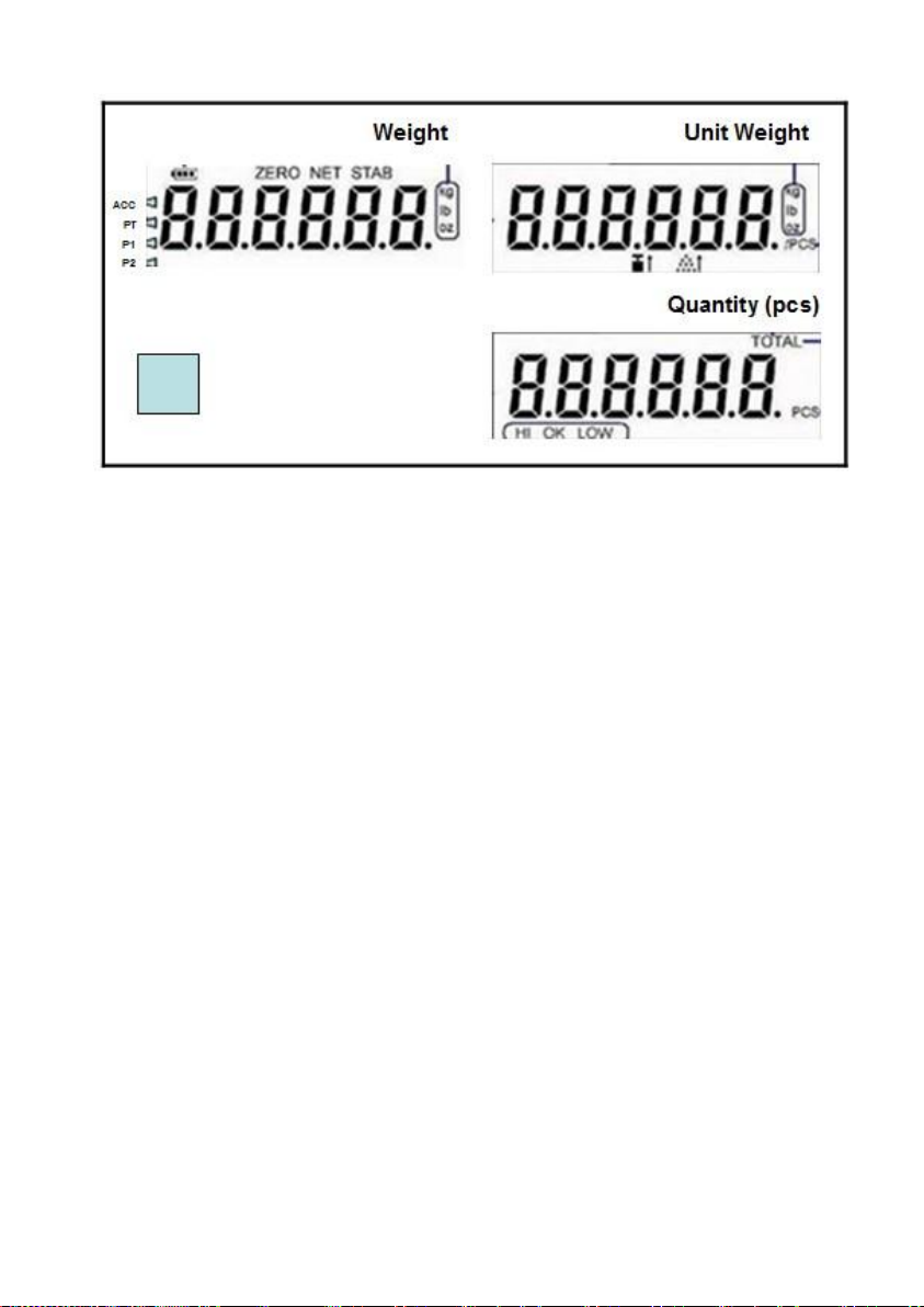
16. BATTERY POWER / LEVEL INDICATOR
This indicator appears to show:-
The instrument is running on the built-in rechargeable battery,
It shows the remaining battery level.
17. ZERO INDICATOR
Visible when instrument at true zero weight status.
18 .NET INDICATOR
Visible when tare function is in effect. The weight being shown on Weight
Panel is net weight.
19. STABLE INDICATOR
Visible when weight reading is stable.
20. WEIGHT UNIT INDICATOR
kg = kilogram, g = gram, lb = pound
21. ARROW INDICATION
Acc=appear when with accumulate result in store
PT =appear after preset tare
P1 =appear when main platform used as current
P2 =appear when extend platform used as current
Page 8

22. UNIT PIECE WEIGHT INDICATOR /pcs
The value left to it is the unit piece weight. This indicator remains visible
during normal operation status.
23. INSUFFICIENT SAMPLE WEIGHT CARNING INDICATOR
Visible when total weight of the sample size is below satisfactory level. If
possible, increase the sample quantity unit this indicator disappears.
24. INSUFFICIENT UNIT PIECE WEIGHT CARNING INDICATOR
Visible when the unit piece weight of the sample is below satisfactory level.
If possible, increase the sample quantity.
25. QUANTITY INDICATOR (pcs)
The value left to it is the quantity of the current transaction. This indicator
remains visible during normal operation status.
26. QUANTITY CHECK RESULT INDICATORS
HI = Quantity is higher than the HI limit set.
OK = Quantity is in between than the low and HI limits set.
LO = Quantity is lower than the LO limit set.
A. WEIGHT PANEL
Weight value is shown here.
B. UNIT PIECE WEIGHT PANEL
Unit piece weight is shown here.
C. QUANTITY PANEL
Quantity value is shown here.
D. BUBBLE LEVEL
Refer to this bubble to obtain a horizontal position for the instrument.
E. DC JACK INPUT
External power adaptor is plugged in here right below the scale
F. RS232 COMPORT
9 pin (DB9) RS232 interface output for connection with computer and other
peripherals.
Page 9

Pin2=RX Pin3=TX Pin5=GND
LOAD CELL
CONNECTOR PIN #
ASSIGNMENT
1
EXCITATION +ve
2
EXCITATION -ve
3
Shield
4
SIGNAL -ve
5
SIGNAL +ve
G. SECONDLY PLATFORM CONNECTION
9 Pin RS232 Connector
1 EXCITATION –
6 EXCITATION +
8 SIGNAL –
9 SIGNAL +
Page 10

4. GETTING STARTED
In order to obtain accurate weighing and counting result, the instrument
must be placed on a strong and level surface horizontally.
Avoid using the instrument in environment where excessive wind flow,
vibration and extreme temperature change exist.
The instrument should be installed from any sources of excessive electrical
noise. For full EMC or for RFI immunity, termination of cable shields and
correct grounding of the instrument is essential.
General warning: -
The instrument is not an explosion proof device.
The instrument is not a water proof device.
Do not open the instrument, no user serviceable parts inside.
Always contact your dealer for service.
The instrument not to be subject to shock, excessive vibration
or extremes of temperature (before or after installation).
4.1 BUILT-IN RECHARGEABLE BATTERY
The instrument is equipped with a built-in rechargeable battery. Before first
time use, recharge it for at least 8 hours to ensure the best battery
performance.
4.2 POWER ADAPTOR
Before plugging in the power adaptor, check and make sure the input
voltage of the adaptor matches with output voltage of the electricity outlet. If
not, contact your dealer immediately.
4.3 CONNECTING OTHER DEVICES
Always turn the instrument off before making any connections or
disconnections with external devices.
Page 11

4.3.1. Connecting with a Computer or Mini printer
4.3.2. Connecting secondly platform
5. INITIAL SETUP
5.1 INTERNAL SETTINGS
Preferred application parameters can be checked or set through internal
functions. Refer to 5.4 for internal function description and setting
procedures.
5.2 HOW TO ENTER AND SELECT INTERNAL FUNCTION
Follow the below steps to enter and select desired parameter of an internal
function.
a. Turn the instrument off and on again
b. Press [TARE] during countdown,
c. The instrument displays RS232
d. Hit [RECALL] to go to CAL then hit [TARE]
e. Enter password when P---- appears “0000”
f. ”The instrument is now in internal function,
5.3 KEY FUNCTION DURING INTERNAL FUNCTION SETTING
[TARE] = Enter, save and return,
[M+] = Quit without saving,
[CHECK] = Go next,
[RECALL] = Go previous,
[CE] = Clear,
Page 12

Page 13

Page 14

Page 15

6. INSTRUCTION FOR USE
6.1 POWER ON /OFF
Press on/off key for 2 seconds on panel, instrument is on and displays: -
a. software and revision number and capacity of instrument,
b. countdown process starts
c. all LCD segments,
After that, the instrument is ready for operation.
d. the Arrow P1 or P2 will show which is the current platform
Press on/off key for 2 seconds when the scale is on and in weighing status
to switch off the scale
6.2 START WEIGHING
a. If zero weight cannot be obtained when unloaded, press [ZERO].
After [ZERO] is pressed, Zero Indicator appears.
Refer to SPECIFICATIONS for maximum zero range,
b. Always place an object onto platter gently. Excessive force applied to
platter may cause damages to the weight sensor inside instrument,
c. Weight of the object is displayed on thus unit automatically,
d. It is a good practice to remove all loads from platter after weighing. It
will prolong the life of the weight sensor inside instrument.
6.3 ABOUT WEIGHT UNIT CONVERSION
The instrument supports conversion among weight units. Press [UNIT] to
shift between kg, g and lb.
To enable or disable a particular weight unit, set it ON or OFF respectively
in internal Unit.
The weight unit being employed before power off will be employed when
turned on again.
Note: Select the suitable unit before counting function. Can not change unit
during counting function.
Page 16

6.4 TARE OFF THE WEIGHT OF A CONTAINER1
1
Tare function is used to temporarily set the instrument to zero (such as
cancelling the weight of a box or a container) in order to get the net weight
result
6.4.1 Enable / Disable Repeat (Multiple) Tare
Depends on internal function setting, repeated (multiple) tare operation may
be enable (Mode 2) or disabled (Mode 1). Contact your dealer for more
information.
When repeat (multiple) tare is enabled: -
1. the instrument will permit multiple tare operations provided that
both of the below requirements are fulfilled: -
The tare operation does not permit a reduction of the value of
the tare;
The tare effect can only be cancelled when there is no load on
the platter.
2. tare effect can only be cancelled when container is removed and
gross weight is zero.
6.4.2 Manual Tare
When a container is used, follow the below steps to tare the weight of the
container off to get a net weight result.
a. Remove all loads from platter,
b. Make sure that the Zero Indicator is on. If not, press [ZERO] to set
weight reading to zero,
c. Place container on platter,
d. Press [TARE],
e. Net Indicator appears to indicate tare is in effect and weight reading
is net weight.
f. To cancel tare effect, remove all loads and container from platter and
press [TARE] ,
The tare weight is deducted from the weighing capacity (Max), reducing the
maximum weight that can be displayed.
Page 17

g. Net Indicator disappears. Tare effect has been removed and weight
2
reading is gross weight.
6.4.3 Preset Tare
This feature enables the user to manually enter the tare weight. During
normal operation, enter the pre-determined tare weight through numeric
keys then press [TARE]. This pre-determined tare value will be deducted.
Arrow for pre-set tare will be shown.
To cancel the preset tare effect, remove all loads from platter then press
[TARE]. Press [ZERO] ,then Arrow for pre-set tare will be disappear
NOTE: -Manual tare is enable when preset tare is in effect. Manual tare will
cancel the effect of preset tare.
6.5 QUANTITY COUNTING
Quantity counting starts with determining the unit piece weight either by
keyboard entry or sampling process.
6.5.1 Entering Unit Piece Weight 2
This method is used where unit piece weight is known and is highly
standardized.
a. Refer to 6.2 to 6.4 for zero, selecting preferred weight unit and tare
operation,
b. Enter the unit piece weight and press [@WT]. The unit piece weight
is now displayed on the Unit Piece Weight Panel.
c. Place a load on the platter. The weight of the load is displayed on the
Weight Panel and the quantity is displayed on the Quantity Panel.
d. To enter new unit piece weight, repeat step b above.
6.5.2 Sampling Process
This method is used where unit piece weight is unknown or the weight of
individual piece is not highly standardized.
When the individual unit piece weight is not standardized, it is strongly
recommended that counting procedures as described in 6.5.2 should be employed.
Page 18

a. Refer to 6.2 and 6.4 for zero, selecting preferred weight unit and tare
3
operation,
b. Place a sample size with known quantity on platter
c. Enter the quantity of the sample through the numeric keypad and
confirm by pressing [SAMPLE].
d. The instrument will automatically determine the unit piece weight and
display it on the Unit Piece Weight Panel3.
e. Step by step add more load onto the platter (or remove part of the
load from the platter),
f. The latest Weight, unit piece weight and total quantity would be
displayed on the corresponding panels,
g. To start a new sampling, repeated step a to d above.
6.5.2 Sampling process between main and extend platform
With a remote weighing base or platform that can be any size .Can switch
between the two scales: Counting sample on light capacity unit and switch
to heavier capacity base when larger quantities are required.
This method is used where unit piece weight is unknown or the weight of
individual piece is not highly standardized.
a. Refer to 6.2 and 6.4 for zero, selecting preferred weight unit and tare
operation on the light capacity platform(make sure the arrow point to
current platform)
b. Place a sample size with known quantity on platter
c. Enter the quantity of the sample through the numeric keypad and
confirm by pressing [SAMPLE].
d. The instrument will automatically determine the unit piece weight and
display it on the Unit Piece Weight Panel
e. Press the [ ①/② ] to switch arrow to larger platform; Now this
platform will be the current platform for quantity counting
f. Step by step add load onto the larger platform
g. The latest Weight, unit piece weight and total quantity would be
At this point, sampling process is completed and Auto Piece Weight
Enhancement Function comes into effect.
Page 19

displayed on the corresponding panels,
To start a new sampling, repeated step a to f above
6.7 MEMORY ACCUMULATION FUNCTION
6.7.1 To Accumulate a Transaction to Memory
a. When quantity is being displayed on Quantity Panel, press [M+] to
and accumulate data of current transaction to memory,
b. The instrument: -
displays “ACC n” on Quantity Panel. ACC denotes data has
been accumulated to memory. Arrow point to ACC is shown.
n donates the number of transactions which have been
accumulated to memory.
displays total accumulated value (total weight and total quantity)
on Total weight panel and Unit Weight Panel.
output transaction printout(s) through the RS232 comport. The
instrument returns to normal operation status after 2 seconds if
the RS232 setting is manual and ACC is on
c. Repeat a for subsequent transactions
6.7.2 Memory Recall and Clearance
a. Remove all loads from platter,
b. Press [MR] to recall total accumulated weight from memory,
c. The instrument displays: -
Display “ACC n” on Quantity Panel. ACC denotes data has been
accumulated to memory. Arrow point to ACC is shown; n donates the
number of transactions which have been accumulated to memory.
Displays total accumulated value (total weight and total quantity) on
Total weight panel and Unit Weight Panel.
e. Press [M+] to print out the accumulate result if the RS232 setting is
manual and format=2
d. At this point: -
Press [ZERO] to quit or,
Press [CE] to clear memory, then [ZERO] to return to normal
operation status.
Page 20

6.8 QUANTITY CHECK FUNCTION4
4
6.8.1 To Enter High and Lo Quantity Limits
The instrument is equipped with quantity check function. Follow the below
steps to trigger checkweighing mode: -
a. During normal operation, press [CHECK].
b. The instrument displays High Limit and current HI limit value is
displayed on Quantity Panel.
c. Press [TARE] to accept or enter a new HI limit through the numeric
keys and then press [TARE] to confirm,
d. The instrument then displays Lo Limit and current LO limit value is
displayed on Quantity Panel.
e. Press [TARE] to accept or enter a new LO limit through the numeric
keys and then press [TARE] to confirm,
Hints: -
1. For normal comparison, set both HI and LO limits,
2. To check only if result is lower or equal to LO (result ≤ LO), set HI
limit = 0,
3. To check only if result is higher or equal to HI (result ≥ HI), set LO
limit = 0,
4. To check if result is equal to a specified value, set both HI limit and
LO limit = the specified value
6.8.2 Visual and Audio Quantity Check Signals
6.8.2.1 Visual signal: - Quantity check result is displayed by one of the
Check Result Indicators located on Quantity Panel.
6.8.2.2. Audio signal: - depends on setting of internal function F5, audio
signal can be triggered when result is = within range, out of
range or turned off.
6.8.3 To Quit Checkweighing Mode
To quit checkweighing mode, set both HI and LO limits to zero.
Quantity check function will not function when weight reading is less than 20d.
Page 21

6.9. Quick setting
Press [SET] to get quick setting parameter ,Press [TARE] to enter and
[M+] and [RECALL] to shift :
PARA, including time, date, back light, auto power off , key beep, unit ,
CHECK , setting checking beep mode, same as mentioned in 5.4
RS232, setting RS232 parameter , same as mentioned in 5.4
RECHARGE setting : To check the currency when charging(mA)
Count : 1) calibration count value; 2)parameter set count value,
Quit setting by press [ZERO]
Quit Count info need by press [ZERO] for 5 seconds
Page 22

7. RS232 DATA OUTPUT
DATA BIT
DESCRIPTION
1~2
MOTION STATUS
US = UNSTABLE
ST = STABLE
3
COMMA SEPARATION
4~5
NET/GROSS
NT = NET WEIGHT
GS = GROSS WEIGHT
6
SIGN (Sign of weight reading)
Positive = space. Negative = minus (-)
7~13
WEIGHT VALUE
7-character string containing the current weight including
location of decimal point.
If there is no decimal point, then the first character is a
5
Data output parameters are fixed as below: -
Data Bit = 8
Parity = None
Stop Bit = 1
There are 2 data output modes (PC and Prt) are available5. PC is for
communication with computer and other peripherals which accepts and
processes continuous data communication. Prt (printer) is for transmission
to printer or other peripherals which accept only single or manual data
transmission.
Baud rate has to be set before proceeding to other settings.
7.1 PC (COMPUTER) MODE
Weight status and data are sent under the PC (Computer) Mode). Data is
transmitted in ASCII code. Data format is listed on below table.
Refer to 5. INITIAL SETUP for setting information
Page 23

space.
14
COMMA SEPARATION
15~16
UNIT
kg = kilogram
g_= gram (_ = blank space)
lb = pound
17
Cr
18
LF
7.2 PRT (PRINTER) MODE
7.2.1 Printing Current Transaction
A standard printout as will be sent through the RS232 Comport when [M+]is
pressed. Refer to Standard Printout Sample on next page for description.
Number of copies sent = the number of copy set in internal function Refer to
5 INITIAL SETUP for more information. If extra copies are needed, press
[M+] again.
7.2.2 Printing the Totalized Accumulated Result
Follow the below steps for to print the totalized accumulated result: -
a. Remove all loads from platter,
b. If zero weight reading cannot be obtained when unloaded, press
[ZERO]
c. Press [MR] then followed by [M+], The below data and format will
be sent,
Refer to Totalized Accumulated Printout Sample on next page for
description.
Page 24

Format=1
TIME 12:08:57
DATE 07.08.2010
No. 0
NET 4.000kg
UNIT WT. 0.5 g
Q'ty PCS
HIGH 5000PCS
LOW 4500PCS
HIGHER THAN LIMIT
TIME 13:48:23
DATE 07.08.2010
No. 4
TOTAL 14997PCS
DATE TIME No. COUNT TARE NET TOTAL UNIT.W
01-01-2001 00:00:10 7 A 10 P 0.0000kg 0.2001kg 10P 20.0052 g
01-01-2001 00:00:20 8 B 56 P 0.00kg 1.12kg 66P 20.0052 g
A and B stand for the data is from which platform
Format-=2
Standard Printout Sample Description
1. Time of printing,
2. Date of printing,
3. M+ sequent number
4. Net weight,
5. Unit piece weight,
6. Quantity,
7. One blank line,
8. One blank line,
9. HI limit set**
10. LO limit set**
11. Quantity Check result
Totalized Accumulated
Printout Sample Description
1. Time of printing,
2. Date of printing,
3. Total No. of transaction
4. Total accumulated quantity
Page 25

8. BATTERY POWER AND RECHARGING
Remaining battery power of the built-in rechargeable battery is displayed on
the BATTERY POWER / LEVEL INDICATOR.
8.1 SYMBOLS AND REMAINING POWER: -
Full Battery: ≥ 6.3V;
2 Blocks: ≥6.0V;
1 Block: ≥5.7V
Frame only: <5.7V
8.2 BATTERY OPERATION TIME
Depends on the battery condition, a fully charge new rechargeable battery
will usually give (when connect to one 350 ohm load cell): -
Around 70 hours of continuous operation with backlight is highest
Around 200 hours of continuous operation without backlight.
8.3 RECHARGE BATTERY
When appears, (when battery is less than 5.7V), it means the
built-in rechargeable battery is at low voltage status. It is recommended to
recharge as soon as possible.
To protect the built-in rechargeable battery, this instrument will power off
automatically when battery voltage is at extremely low level (when battery is
at around 5.4V). If this is the case, do not attempt to power this instrument
on. Recharge this instrument immediately. Fail in doing so may cause
unrecoverable damage to the built-in rechargeable battery.
Battery charging status is shown on LCD CHARGE STATUS INDICATOR:
When charge , the status is shift of 1 block,2 block ,3 block and only frame
Battery recharge is possible while operating. Overcharge protection circuit
is built inside to prevent battery damages caused by overcharge.
Heat will be generated during recharging and it is normal to feel minor heat
at front housing of this instrument.
Page 26

9. ERROR CODES
Error
Code No.
Description
Err 1
Time value error
Err 2
Date value error
Err 3
Logic error. LO limit is higher than HI limit
(and HI is not = 0)
Err 4
Not sense the loadcell signal
Err 5
Exceed maximum power on zero range
Err 6
Exceed maximum manual zero range
Err 7
Tare operation error
Err 8
Offset out of range / unstable during power on
--oL--
Overload (Gross weight is more than Max plus 9d)
Page 27

10. DAILY CARE AND MAINTENANCE
Clean the instrument with a soft, damp cloth. If necessary, use a mild
detergent in water,
Do not use any harsh, abrasive material, acetone, volatile solvent,
thinner or alcohol for cleaning,
Verify the accuracy of this unit periodically. Re-calibrate this unit if
necessary. In some countries, calibration requires authorized /
qualified agent. Contact your dealer for more information,
Store this unit in a dry and clean place,
Recharge battery before and every 2 months during long time
storage.
 Loading...