

DIGIWAY PTY P750, P550 Instruction Manual
DIGIWAY PTY LTD
1
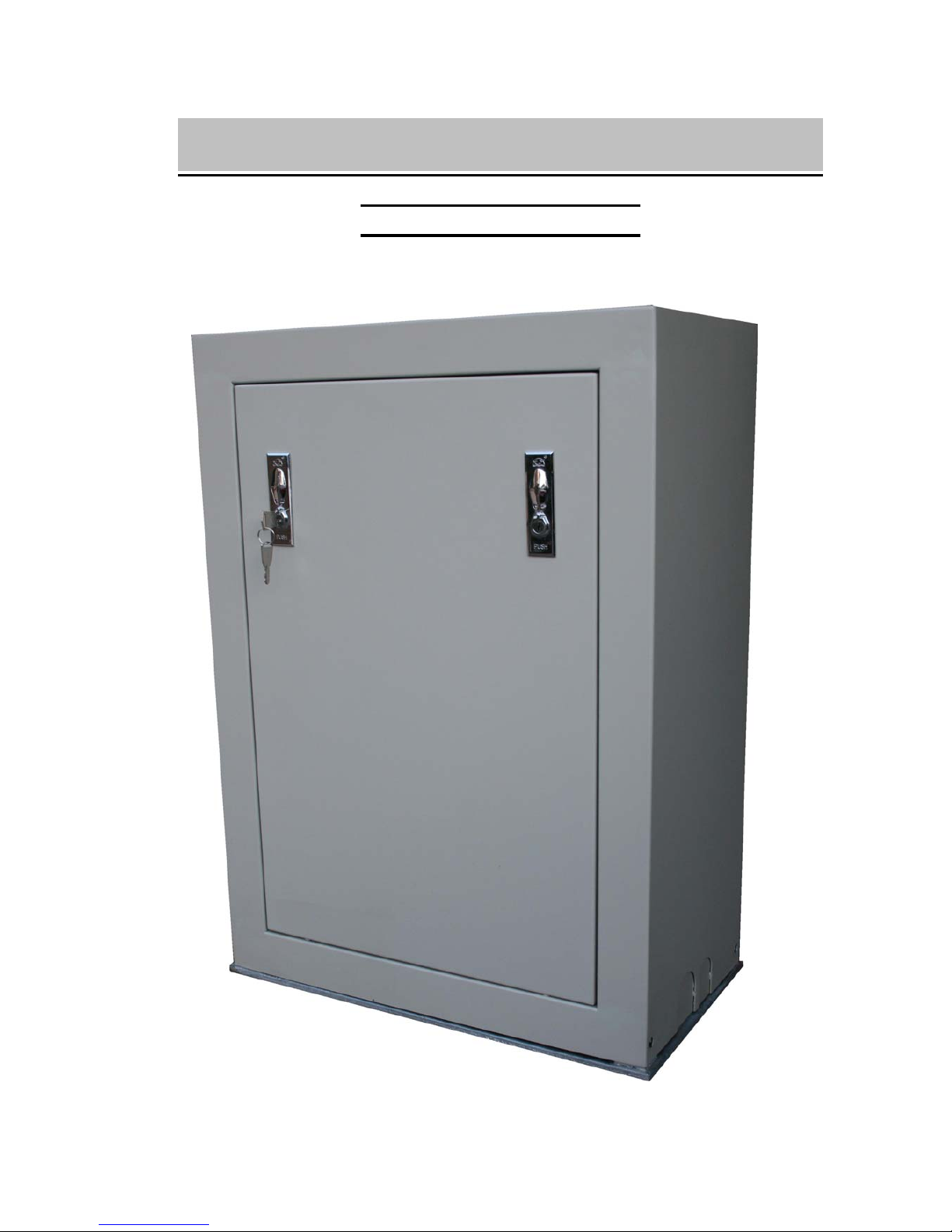
P750 Sliding Gate Motor
P550 Sliding Gate Motor
Version -V2.X
INSTRUCTION MANUAL
DIGIWAY PTY LTD
2
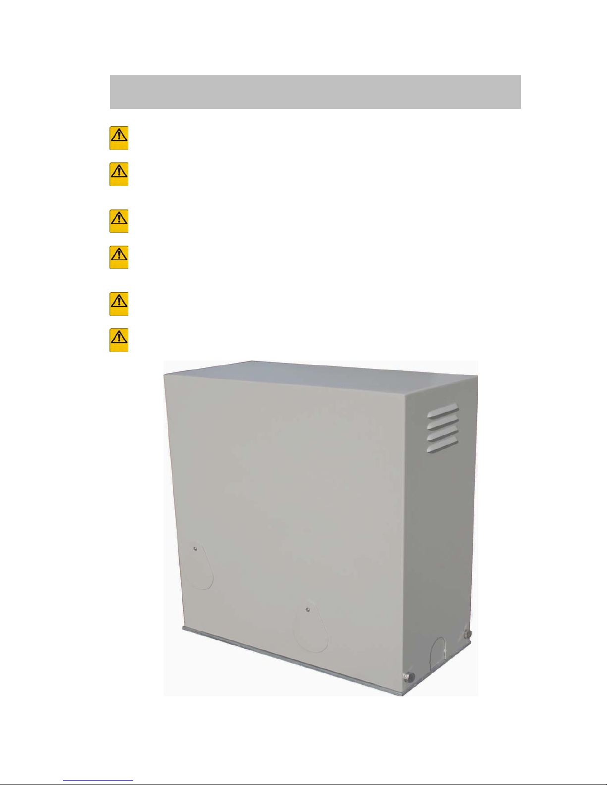
ATTENTION To prevent electrical shock, disconnect from power source before installing or service
ATTENTION Electricity and power motors associated accessories could be fatal or at least cause
seriously injury. All main voltage wiring must be installed by a licensed electrician.
ATTENTION Additional safety device MUST be fitted such as Photo Electric Beam, Loop Detectors.
ATTENTION Before do the manual release, the mains power switch must be off even there is no
power.
ATTENTION Before power on, the manual release MUST engaged
ATTENTION Gate opened stopper and closed gate stopper MUST be installed.
P550 Sliding Gate Motor
IMPORTANT SAFETY WARNING
DIGIWAY PTY LTD
3
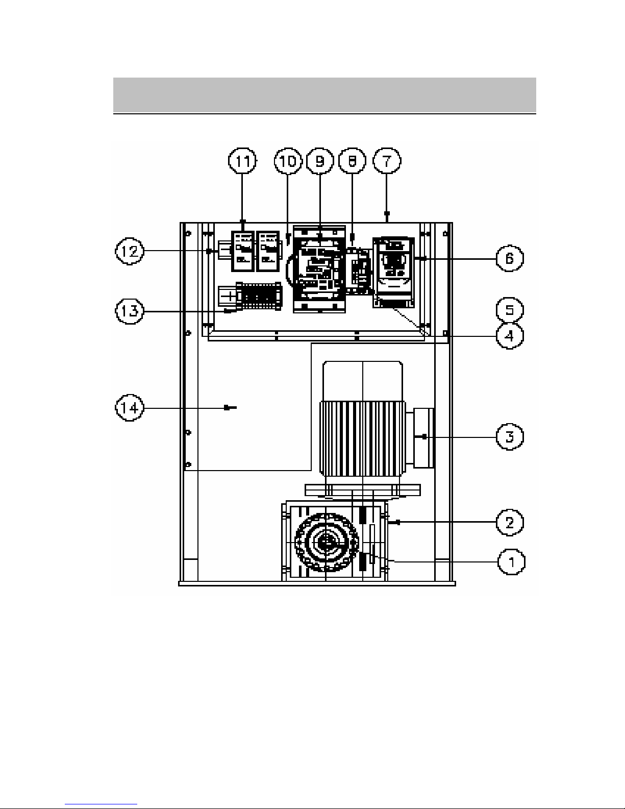
Fig -1
1) Manual Release bolts 2) Gear box
3) Motor 4) Circuit breaker
5) Terminals 6) Inverter
7) Perspex 8) EMC filter
8) Main control board 10) Transformer
11 Loop detector (option) 12 Din rail
13) Access control terminals 14) Room for other accessary
GENERAL LAYOUT
DIGIWAY PTY LTD
4
1. General Descriptions
The P550 and P750 sliding gate motors was designed for heavy duty industry track gate or cantilever
gate. Heavy duty three phase industry motor driven by VSD (variable speed drive), gate can run at
different speeds. Built in encoder and intelligent controller combination can make the gate running
more smoothly. The controller can receive the signals from swipe card, loop detectors, remote control,
photo-electric beams and any kind of access control system. Galvanised metal sheet and powder coated
high quality cabinet(1.5mm thickness) has remove door (P750) and plenty of room for the access
control accessaries including din rail mounting. 50VA transformer (12V/24v/2A) can directly drive
magnetic lock, warning lights etc.
2. Technical Specifications
Power supply 230/240V AC at 10A
Output voltage 230V AC three phase (via) inverter, Max. 0.75KW
Motor rate Three phase two poles 0.55KW (P550) or 0.75KW (P750)
Gate type Track or cantilever
Drive speed Up to 700mm/sec (with big opinion)
Max. gate length No limitation
Fully programmable Auto close time, PE trig close time etc.
Accessories power supply 12V@2A or 24@2A, Max. 50VA, protected by 1A fuse
3. Control Board layout
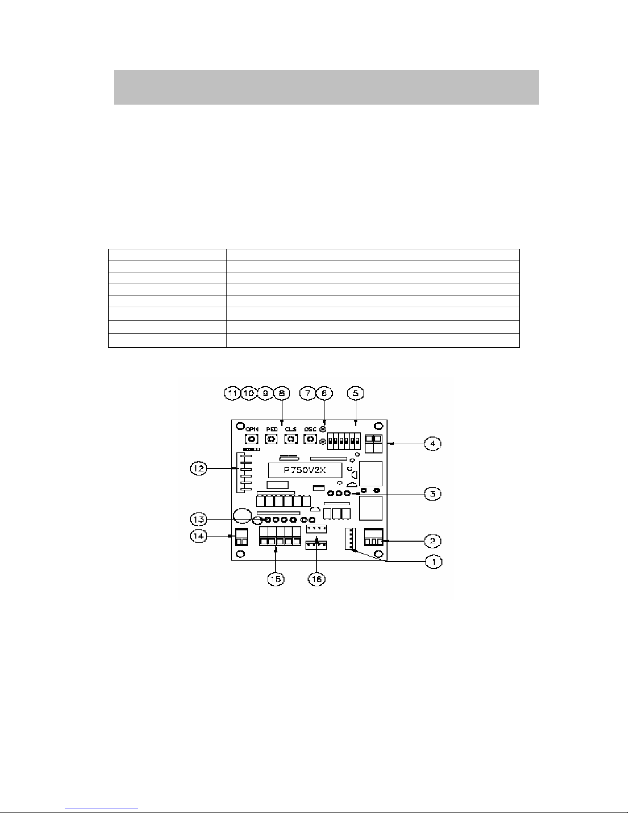
Fig-2
1) Plug to the inverter 2) Lock relay output
3) Drive signal LED 4) Gate closed relay output
5) DIP switch 6) Gate status display LED-Green
7) Gate status display LED-Red 8) OSC open/stop/close button
9) CLS close button 10) PED pedestrian button
11) OPN open button 12) 6 pins remote plug
13) Control signal display LED 14) Input interface power 12V AC
15) Control signal plug 16) Encoder plug
CONTROL INPUIT AND BUTTON
 Loading...