

DIGIWAY PTY LTD
SW50 V2.X Dual Swing Gate Motor
INSTRUCTION MANUAL
- 1 -

IMPORTANT SAFETY WARNING
Electricity and power motors associated accessories could be fatal or at
least cause seriously injury. Digiway suggested some safety device to be
used so as to prevent personnel from being injured by motorized device
being controlled. All main voltage wiring must be installed by a licensed
electrician.
Recommended install PE beams or loop detectors for additional
safety.
Do not operate gate unless gate is in full view and free from objects.
Remote control must be keep away from children.
- 2 -

MAIN FEATURES
1. General Descriptions and features
1.1 General descriptions
It is recommended reading and understanding this manual before start to install the control board.
Some features and idea are new. So take some time to read through the manual to get better
understanding of the board. That will save your time during installation and get the best benefit
from the control board.
1.2 General features
SW50 is designed for most of domestic swing gate. It can be mounted on brick wall/pier or steel
post. The arm supplied can be met most of application situations. If special need, customer can
modified arm or ask supplier/dealer to contact manufacturer for different arm.
Before installation must check:
A) Gate moves freely by hand without any difficulty in either open and closing directions.
B) The post or pier must be strong enough.
C) Gate must have open and closed stopper
D) 240V 10A power point must be available within one metre of the post/pier
E) If there is not enough side room, minimum side room requirement see following drawing.
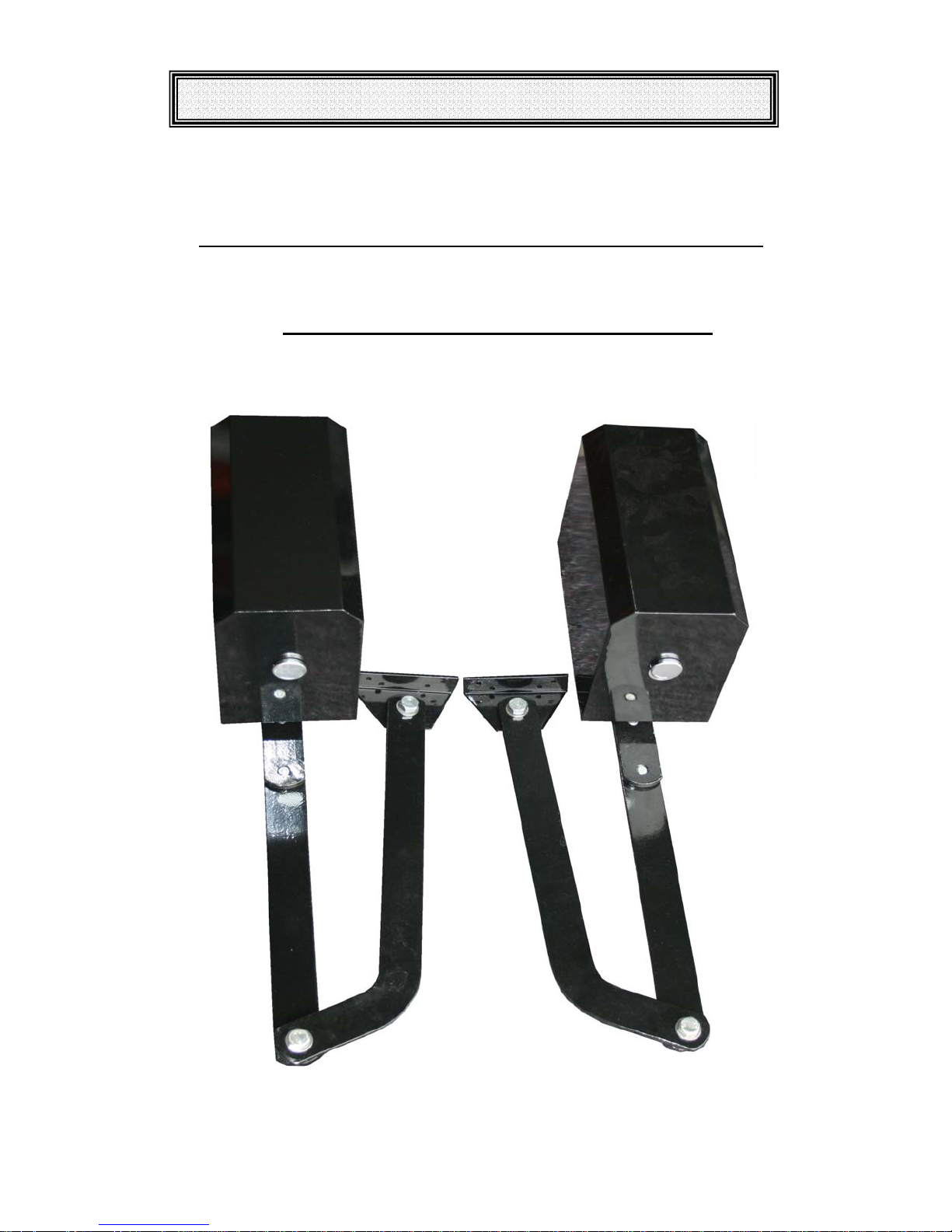
2. Motor installation
Here are the arms. Different combination (some need minimum modify, drilling holes) and
different motor mounting positions can drive different gate.
Fig. 1 SW50 different arms
- 3 -
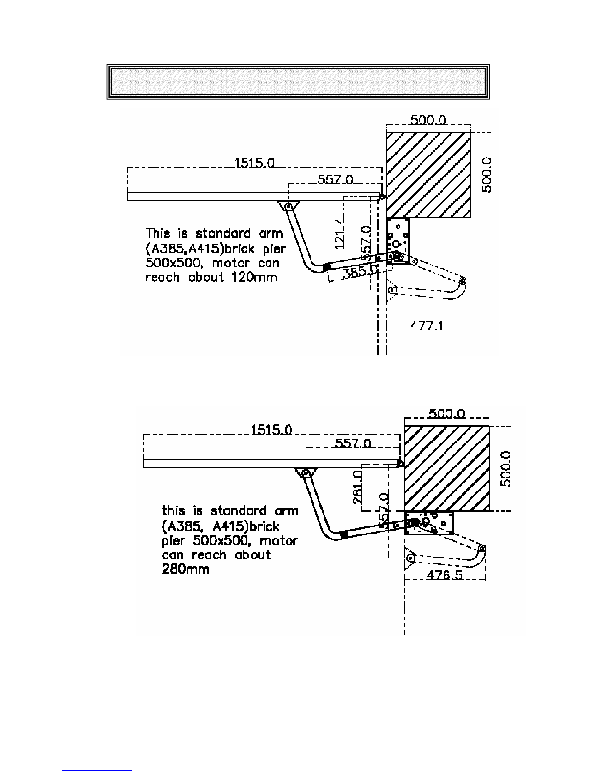
GATE MOTOR MOUNTING
Fig. 2 A385, A415 arms swing in vertical mounting
Fig. 3 A385, A415 arms swing in parallel mounting
- 4 -

GATE MOTOR MOUNTING
Fig. 4 A385, A585 arms swing out vertical mounting
Fig. 5 A385, A585 C800 arms swing in vertical mounting small side room
- 5 -

GATE MOTOR MOUNTING
Fig. 6 A585, A585 arms swing in vertical mounting
Fig. 7 SW50 motor side view
- 6 -

GATE MOTOR MOUNTING
Fig. 8 SW50 clutch/manual release
Manual operation: Disengage motor by undo manual release bolt several turns, so that motor
basis can move on chassis, hold motor move away from output shaft. To re-engage motor by move
motor towards to output shaft and then tight manual release bolt.
- 7 -

GATE MOTOR CONTROLLER
3. Control board
The SW50 swing gate motor controlled by DC2 control board, which has following features:
• Control one or two 12 or 24V DC motors. For Swing gates, Sliding Gates, Roller shutter
doors etc.
• Limit switch inputs, N/C or N/O
• Lock or lights relay output.
• Adjustable timers: auto close time and PE trig auto close time.
• Pedestrian cycle
• Safety control inputs.
• Self-learn soft start and soft stop.
View of Control board
1 243
5
8
9 12 13
10 11
1. OPN open push button
2. CLS close push button
3. PED pedestrian open push button
4. OSC stop push button
5. Gate status display, open green, close red
6. Mode selection DIP switch
7. Close motor force (reverse power)
8. Control inputs terminals.
9. Limit switch input
10. Lock output relay
11. M1 output
12. M2 output
13. Accessary power supply12V/24V
14. Battery terminals
15. Power supply 12 V or 24V AC.
6
Fig. 9 DC2 PCB
7
14 15
- 8 -

GATE MOTOR CONTROLLER
3.1 Control inputs
Fig.10. DC2 PCB dimensions and mounting holes
Control Terminals
OPN ----- N/O open input.
PED ------ N/O pedestrian open push button, only open motor-1
CLS-------N/O Close Gate
OSC------ N/O pedestrian open push button, only open motor-1
STP-------N/C Stop motor
PEB ------ N/C photo electrical beams
OL1 ------ Motor 1 open limit switch, N/C or N/O selected by DIP4
CL1 ------ Motor 1 close limit switch, N/C or N/O selected by DIP4
OL2 ------ Motor 2 open limit switch, N/C or N/O selected by DIP4
CL2 ------ Motor 2 close limit switch, N/C or N/O selected by DIP4
Plug in receiver or on board receiver
Buttons
OPN button ---- full (M1&M2) open gate and used for settings
PED button ----- Ped (M1) open gate and used for settings
CLS button ----- CLS gate and used for settings
OSC button ----- Stop motor
3.2 DIP Switch Settings
DIP1---- SET ON—set, OFF – Run
DIP2---- SYNC ON—SYNC mode, OFF – No Sync mode
DIP3---- LKPS ON—Lock Pulse Output, OFF – Lock Presence Output
DIP4---- NOLS ON—N/C limit switch, OFF – N/O limit switch
DIP5---- PECL ON—PE trig Auto Close, OFF – No PE trig Auto close
DIP6---- AUCL ON—Auto Close Mode, OFF – No Auto close
- 9 -

CONTROLLER SETTINGS
3.3 Motor Force
In N/C limit switch mode, if any motor current over current setting, both motors will stop in
opening cycle or reopen in closing.
In N/O limit switch mode (this model also called no limit switch, current detect mode), if M1 over
current settings, only stop M1, while M2 current over current setting, only stop M2.
3.4 Power input
12 or 24V AC power input. 12VAC for 12VDC motor, 24VAC for 24V DC motor
3.5 Battery Backup
12V battery --- 12VDC motor, 12VAC input.
24V battery --- 24VDC motor, 24VAC input.
Solar regulator output can be direct connected to this terminal if in case of solar application.
3.6 Motor output
M1: Motor 1 output. M2: Motor 2 output
3.7 Power output
Power out for accessaries. About 14V----- 12VAC supply, about 26V------24VAC supply
3.8 Timers setting
Push Buttons functions
Button SET ON---Setting SET OFF---Running
OPN Sync Delay Time Open gate
PED Lock Pulse Time Partial open gate
CLS PE Trig Close Time Close gate
OSC Auto Close Time Stop gate
Note
Set time settings
Turn SET on, red and green LED flashes a little fast alternatively.
Push and hold on OPN for Sync Delay Time
Push and hold on PED for Lock Pulse Time
Push and hold on CLS for PE Trig Close Time
Push and hold on STP for Auto Close Time
Factory setting
Timer F/Setting Step Setting Method Range
Sync Delay Time 2 sec. 0.1 sec. SET on + OPN Button 0-25 sec.
Lock Pulse Time 2 sec. 0.1 sec. SET on +PED Button 0-25 sec.
PE Auto close Time 2 sec. 0.1 sec SEC on + CLS Button 0-25 sec
Auto Close Time 30 sec. 0.1 sec. SET on + PRO Button 0-6553 sec
To restore factory setting, turn power off and set DIP1 (SET) on, push and hold
CLS button, then power on. While hold CLS button, set SET1 off and then release
the CLS button. Now controller restored factory setting from memory.
Get into special setting model:
Turn power off, set DIP1 o, push and hold CLS button, power up. Then release CLS button. Now
controller gets into special setting model
.
- 10 -

4 Motor Connections
4.1 Two wires motor
MOTOR CONNECTION
To controller
Fig.11. Two wires system with limit switch
- 11 -

MOTOR CONNECTION
4.2. Five Wires motors (SW50 config to 2 wires system)
Five wires motor drawing as the drawing.
.
Fig.12. Five wires system with limit switch
4.3. Two wires motors without limit switch
DC2 controller can also control linear drive motor without limit switch. Set pot/motor force
according to the motor. Controller detects motor current to stop motor.
4.4 Step by step set up motor.
a) Mounting and connect motor
b) Disengage cutch and push two gates in middle position, then engage clutch. Power up,
push OPN button, gate should open, if any gate goes close direction, switch motor two
wires.
c) Adjust limit switch (make sure DIP4 limit switch selection is matched to limit switch).
(1) If 5 wires system, turn power off and disengage clutch and setting limits switch.
Move gate to closed potion and adjust closed limit stop to touch the limit switch
and this limit should connect to closed limit switch in put on control board. Open
gate to opened position do the same things for opened limit switch.
(2) If 2 wires system with limit switch with diode, need keep power on, push remote,
while gate is running(either open or close), using screw driver touch limit switch,
so can find out which limit is for open or close. Turn power off, then disengage
clutch, push gate and set up limit switch.
(3) If two wires system without limit switch, in this case, opened and closed
mechanical stopper must be installed. Adjust motor force pot to suit actual gate
power requirement.
d) Power up, use remote or push button to operate gate. Controller will automatically learn
soft stop positions. After two fully close and open cycles, auto-learn procedure finish.
- 12 -

TROUBLE SHOOTING GUIDE
5 Trouble shooting guide
5.1 General checking
Normally if installation is done properly, there would be trouble free. If in case of malfunction,
please checking as following steps.
1) Check the DIP setting limit switch selection is right.
2) Gate status LED green (open) and red (close), one or both should be flashing depending on the
gate position. If not flashing, please check the power supply and 12V DC output circuits if there is
a short circuits.
5.2 Gate not open
1) Check the limits switch type selection if it is right.
2) Push button on the control board, if gate status green LED flashing and red LED off, please
check motor fuse and motor.
5.3 Gate not close
1) Check the limits switch type selection if it is right
2) Check the DIP switches auto close mode selection if it is right.
3) Check control input. If one or more of OPN, PED, PEB input LED are on, which means access
control system hold gate open.
- 13 -
 Loading...