

DIGIVISION STREAMERH264 User Manual

Distributore per l’Italia : http://www.digivision.it
_
DIGIVISION srl - Viale Piave 3 - 20129 MILANO Italy
telefono ++39 02 7600 7932 - fax ++39 02 7601 6305
Ufficio vendite e-mail : vendite@digivision.it
STREAMERH264 UserManual

www.digivision.it StreamerH264 User Manual
Distributore per l’Italia : http://www.digivision.it
_
DIGIVISION srl - Viale Piave 3 - 20129 MILANO Italy
telefono ++39 02 7600 7932 - fax ++39 02 7601 6305
Ufficio vendite e-mail : vendite@digivision.it
-1-
Gent. Cliente,
La ringraziamo per la preferenza accordataci e Le indichiamo alcuni piccoli
suggerimenti per il Setup e l’installazione del suo nuovo STREAMERH264:
Dopo aver estratto l’ apparecchio dalla sua confezione, lo posizioni in un posto
areato evitando il posizionamento in armadi ecc. Colleghi la Camera Sony, se
ha acquistato anche questo prodotto da noi, o la sua camera o sorgente video,
successivamente colleghi l’ apparecchio in rete tramite apposito cavo RJ45,
infine colleghi l’ alimentatore in dotazione, potrà se lo ritiene opportuno altresi
collegare un monitor di controllo VideoComposito collegandolo al connettore
BNC di uscita dello STREAMERH264.
Una volta avviato l’ apparecchio, potrà accedervi via rete usando l’ utility
“truemanager.exe” che troverà nel CD in dotazione o in mancanza di quest’
ultimo potra scaricarlo all’ indirizzo
www.digivision.it/downloads/STREAMERH264/H264CD.zip
questo file
contiene le utility, i manuali ed i software per la gestione del suo
STREAMERH264.
In alternativa puo indirizzare l’ apparecchio con uno dei seguenti indirizzi di IP:
“192.168.1.10” oppure “192.168.10.100” usando Internet Explorer e
installando sulla sua interfaccia di rete una classe di ip che riconduca ad una
delle due listate sopra, in qualunque caso lo user e la password impostate di
default sono: username “admin” password “1234” esclusi gli apici, se dovesse
trovare delle difficoltà ad eseguire queste operazioni La invitiamo ad inviare
una mail a lab@digivision.it
avendo per oggetto la seguente riga
“STREAMERH264 info sull’ installazione”.

www.digivision.it StreamerH264 User Manual
Distributore per l’Italia : http://www.digivision.it
_
DIGIVISION srl - Viale Piave 3 - 20129 MILANO Italy
telefono ++39 02 7600 7932 - fax ++39 02 7601 6305
Ufficio vendite e-mail : vendite@digivision.it
-2-
ATTENZIONE nella funzione FULL DUPLEX.....
1) in Modalita’ full duplex : Maximum bitrate supportato 2 Mbps
( in Modalita’ Encoder Maximum bitrate supportato 4 Mbps )
2) Attenzione alcune combinazioni nel sistema
in full duplex NON sono supportate !!
Duplex system 1 Duplex system 2 Supporto
Ntsc PAL Ntsc PAL
720x480 (720x576) 720x480 (720x576) No
720x480 (720x576) 352x240 (352x288) SI
720x240 (720x288) 720x240 (720x288) No
352x480 (352x576) 352x480 (352x576) SI
352x480 (352x576) 352x240 (352x288) SI
352x240 (352x288) 352x240 (352x288) SI
In caso di bisogno inviare una email a lab@digivision.it
o telefonare allo 02 7600 7932 chiedendo del supporto tecnico per
STREAMER H264

www.digivision.it StreamerH264 User Manual
Distributore per l’Italia : http://www.digivision.it
_
DIGIVISION srl - Viale Piave 3 - 20129 MILANO Italy
telefono ++39 02 7600 7932 - fax ++39 02 7601 6305
Ufficio vendite e-mail : vendite@digivision.it
-3-
Safety Precaution
Make sure to turn off the power before installing STREAMERH264.
Do not install under the direct sunlight or in dusty areas.
Make sure to use the product within the temperature and humidity specified in t he
specification.
Do not operate the product in presence of vibrations or strong magnetic fields.
Do not put electrically conducting materials in the ventilation hole.
Do not open the top cover of the product. It may cause a failure or electric shock on
the components.
To prevent from overheating, make sure to keep the distance at least 10cm from the
ventilation hole.
Check for proper voltage before connecting the power.
We appreciate your purchasing StreamerH264 series. Before installing the
product, please read the following with care.

www.digivision.it StreamerH264 User Manual
Distributore per l’Italia : http://www.digivision.it
_
DIGIVISION srl - Viale Piave 3 - 20129 MILANO Italy
telefono ++39 02 7600 7932 - fax ++39 02 7601 6305
Ufficio vendite e-mail : vendite@digivision.it
-4-
Table of Content
Table of Content
1. Introduction
1. About User Manual
2. Feature
3. Product and Accessories
4. Part Names and Functions
5. System Modes and Connections
2. Installation
1. Connecting Video
2. Connecting Audio
3. Connecting Serial Ports
4. Connecting Sensor and Alarm
5. Connecting Power
6. Check if It Works
3. System Operation
1. LED Display
2. Remote Video Monitoring
3. Initialization of IP Address
4. Remote Configuration
1. Remote Configuration
2. Encoder Configuration
2.1 System Configuration
2.2 Video Configuration
2.3 Audio Configuration
2.4 Network Configuration

www.digivision.it StreamerH264 User Manual
Distributore per l’Italia : http://www.digivision.it
_
DIGIVISION srl - Viale Piave 3 - 20129 MILANO Italy
telefono ++39 02 7600 7932 - fax ++39 02 7601 6305
Ufficio vendite e-mail : vendite@digivision.it
-5-
2.5 Serial Port Configuration
2.6 Event Configuration
2.7 Preset Configuration
2.8 Record Configuration
2.9 User Configuration
3. Decoder System
3.1 Network Configuration
3.2 Display Configuration
4. Duplex System
5. Trouble Shooting
Appendix A: Sensor and Alarm Port
1. Sensor Port
2. Alarm Port
Appendix B: Serial Port
1. RS-232 Port
2. RS-422/485 Port

www.digivision.it StreamerH264 User Manual
Distributore per l’Italia : http://www.digivision.it
_
DIGIVISION srl - Viale Piave 3 - 20129 MILANO Italy
telefono ++39 02 7600 7932 - fax ++39 02 7601 6305
Ufficio vendite e-mail : vendite@digivision.it
-6-
1. Introduction
1. About User Manual
The User Manual is to provide information on operation of the high quality Video + Audio
corporate communication system STREAMERH264. In this guide, information on
installation, operation, configuration of STREAMERH264 is written as well as how to
trouble shoot in case problems arise.
2. Feature
STREAMERH264 is a video and audio corporate communication system based on IP
network through LAN, ADSL/VDSL, and Wireless LAN. The STREAMERH264 series
operates as one of the three modes: Encoder, Decoder and Duplex. Encoder system
compresses and transmits video data. Decoder receives and decompresses the video
data. Duplex system provides bi-directional transmission of video data.
Video
- High-quality compression algorithm, H.264
- Compression in various resolution: CIF, Half-D1, D1
- Wide range of video transmission rate: 32kbps ~ 4Mbps
- Various transmission mode: CBR, VBR
- Motion detection
Audio
- Multi-transmission mode: Uni-direction (Encoder -> Decoder, Decoder ->
Encoder), Bi-direction

www.digivision.it StreamerH264 User Manual
Distributore per l’Italia : http://www.digivision.it
_
DIGIVISION srl - Viale Piave 3 - 20129 MILANO Italy
telefono ++39 02 7600 7932 - fax ++39 02 7601 6305
Ufficio vendite e-mail : vendite@digivision.it
-7-
Network
- Static IP and Dynamic IP(DHCP, PPPoE)
- One to one and one to many connection
- Multicasting
- Automatic transmit rate control according to network condition
Serial Data
- Two serial ports
- Various PTZ camera protocol
- Data pass-through mode: Serial data communication between Encoder –
Decoder
Sensor and Alarm
- Connections to external sensor and alarm devices
- Event Alarm
USB
- Connection to internal or external USB storage for remote access
User Interface
- System status display utilizing OSD(On Screen Display)
- System configuration using Internet Explorer
Reliability
- Reliable embedded system
- System recovery utilizing dual watch-dog functions
www.digivision.it StreamerH264 User Manual
Distributore per l’Italia : http://www.digivision.it
_
DIGIVISION srl - Viale Piave 3 - 20129 MILANO Italy
telefono ++39 02 7600 7932 - fax ++39 02 7601 6305
Ufficio vendite e-mail : vendite@digivision.it
-8-
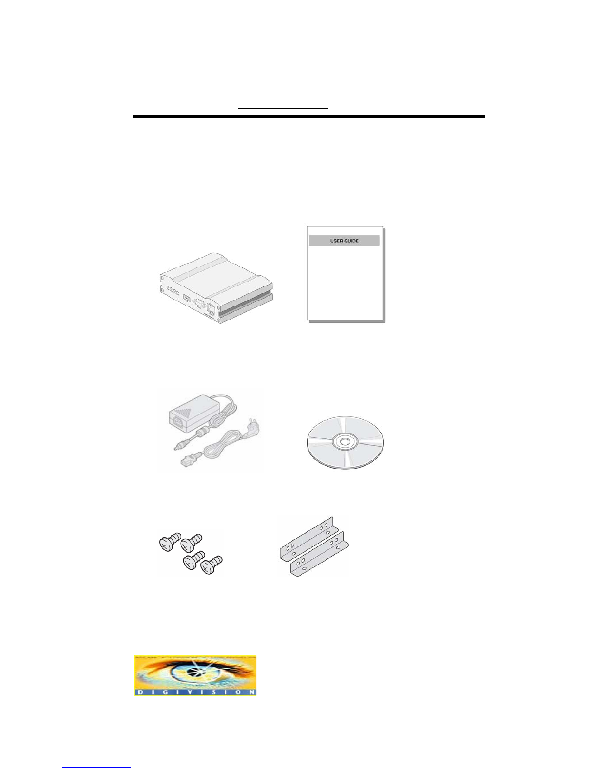
3. Product and Accessories
STREAMERH264 System User Manual
Power adaptor and cable CMS S/W CD
Screws Brackets
<Picture 1> Product and Accessories
www.digivision.it StreamerH264 User Manual
Distributore per l’Italia : http://www.digivision.it
_
DIGIVISION srl - Viale Piave 3 - 20129 MILANO Italy
telefono ++39 02 7600 7932 - fax ++39 02 7601 6305
Ufficio vendite e-mail : vendite@digivision.it
-9-
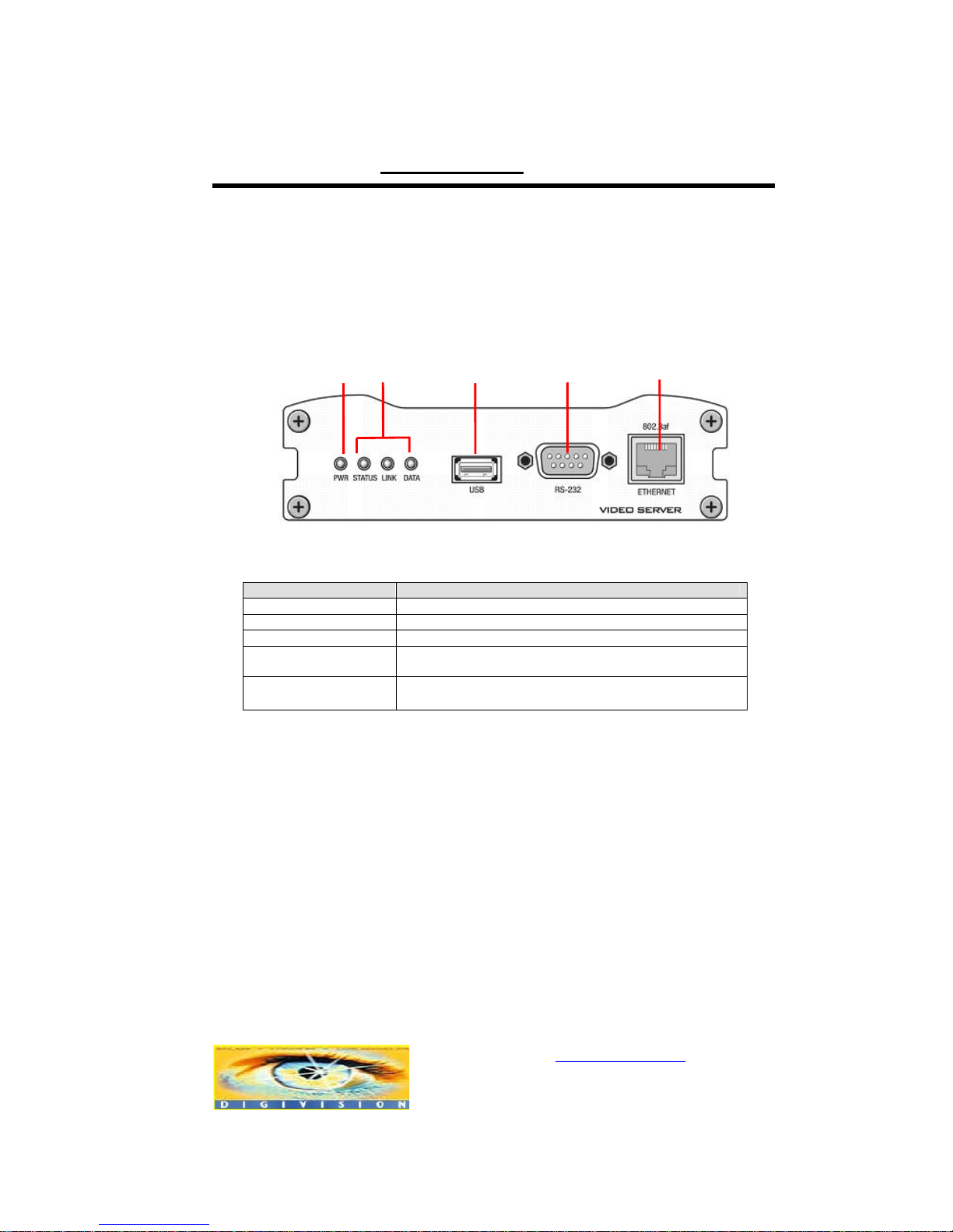
4. Part Names and Functions
Front View
Parts Function
n Power LED(PWR) Display power On/Off condition
o Other LEDs Display system status
p USB USB port for any USB device
q RS-232C Serial communication port 1 (COM1) for PTZ control or
bi-directional command pass-through
r LAN(Ethernet) 100/10-base-T Ethernet interface
n
o
p
q
r
www.digivision.it StreamerH264 User Manual
Distributore per l’Italia : http://www.digivision.it
_
DIGIVISION srl - Viale Piave 3 - 20129 MILANO Italy
telefono ++39 02 7600 7932 - fax ++39 02 7601 6305
Ufficio vendite e-mail : vendite@digivision.it
-10-
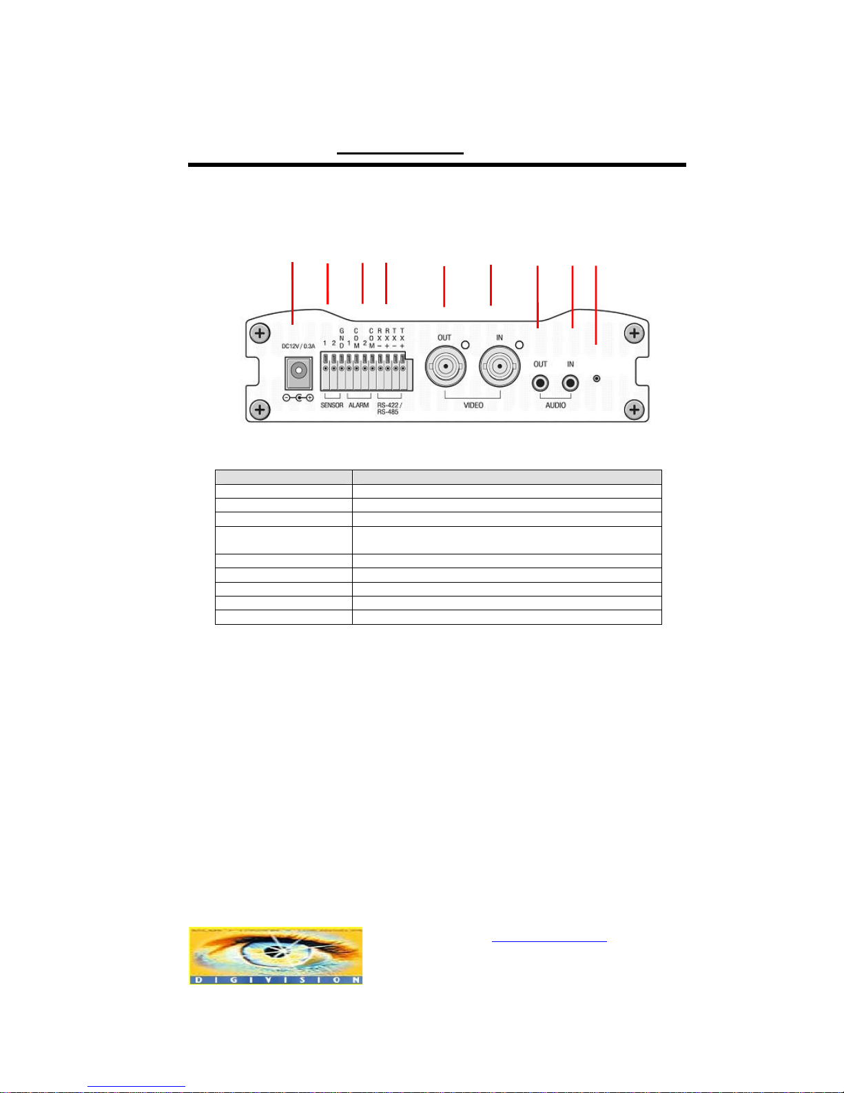
Rear
Connector Function
n POWER IN DC 12V power input
o SENSOR Sensor input
p ALARM Relay output
q RS-422/485
(COM2)
Serial port 2 (COM2) for PTZ control and etc. Support
RS-422 and RS-485 protocol
rVIDEO OUT Video output
sVIDEO IN Video input
tAUDIO OUT Audio output
uAUDIO IN Audio input
v RESET Reset button for network reset
5. System Modes and Connections
The STREAMERH264 system operates in one of three modes: Encoder, Decoder,
Duplex. STREAMERH264 systems can be connected in either 1-to-1 fashion where one
encoder is connected one decoder or 1-to-many fashion where one enc oder connected
to many decoders. Also, it is possible to connect in duplex mode on both sides to have
bi-directional transmission of video images.
Following chart shows possible combinations of video, audio and serial data
transmission.
r
s
t u v
o
p q
n
www.digivision.it StreamerH264 User Manual
Distributore per l’Italia : http://www.digivision.it
_
DIGIVISION srl - Viale Piave 3 - 20129 MILANO Italy
telefono ++39 02 7600 7932 - fax ++39 02 7601 6305
Ufficio vendite e-mail : vendite@digivision.it
-11-
System Mode Video Audio Serial Data
Encoder Transmit Transmit/Receive Transmit/Receive
Decoder Receive Transmit/Receive Transmit/Receive
Duplex Transmit/Receive Transmit/Receive Transmit/Receive
Therefore, the system modes are defined by the video communication and all s ystem
modes are capable of bi-directional transmission of audio or serial data.
Topology
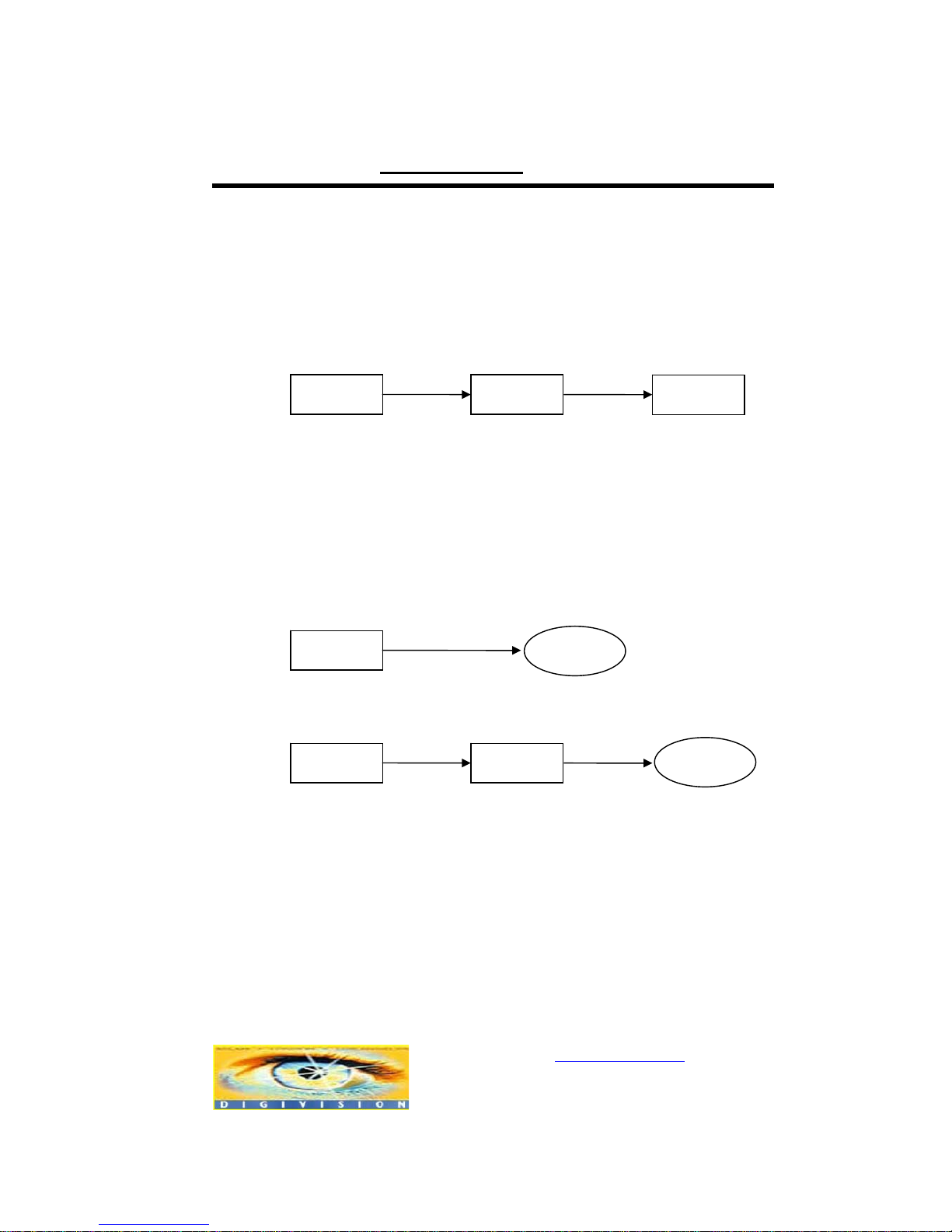
Generally, the encoder and the decoder are connected in 1-to-1 mode. To support
specific situations, 1-to-many connection is also supported.
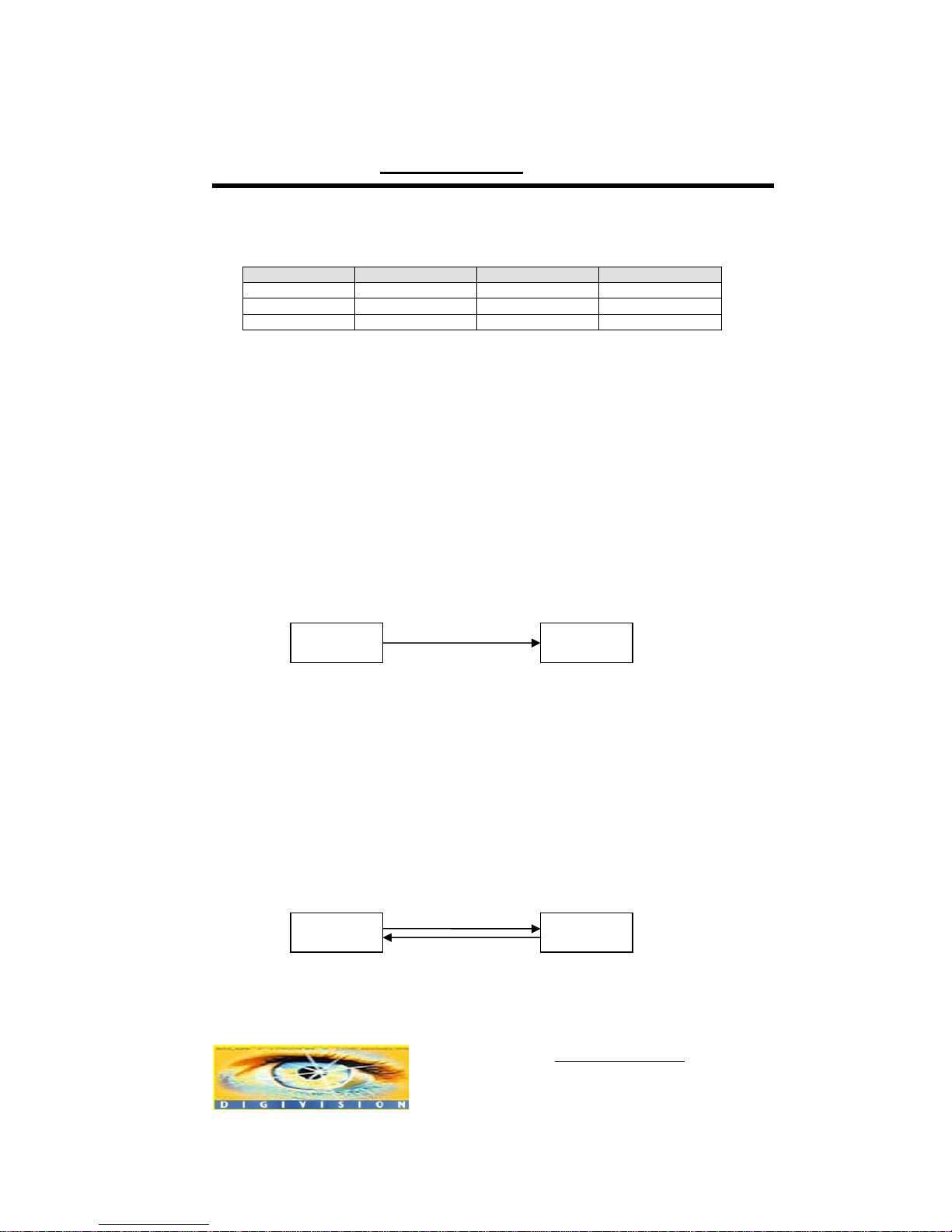
1:1 Connection (Unidirection)
Mostly used configuration is 1 to 1 connection. An encoder is installed at a site where
video images can be transmitted and a decoder is installed at a center location to
receive and view the video images on analog monitor. Audio and serial data are
transferred in either direction.
1:1 Connection (Bi-direction)
Duplex Duplex
Site
Remote Center
Encoder Decoder
Site
Remote Center
www.digivision.it StreamerH264 User Manual
Distributore per l’Italia : http://www.digivision.it
_
DIGIVISION srl - Viale Piave 3 - 20129 MILANO Italy
telefono ++39 02 7600 7932 - fax ++39 02 7601 6305
Ufficio vendite e-mail : vendite@digivision.it
-12-
It is another way to use 1 to 1 connection. In this type of connection, not only aud io but
also video is transferred bi-directionally. The video capability
(resolution/framerate/bitrate) in duplex mode connection is restricted than that in
unidirectional connection.
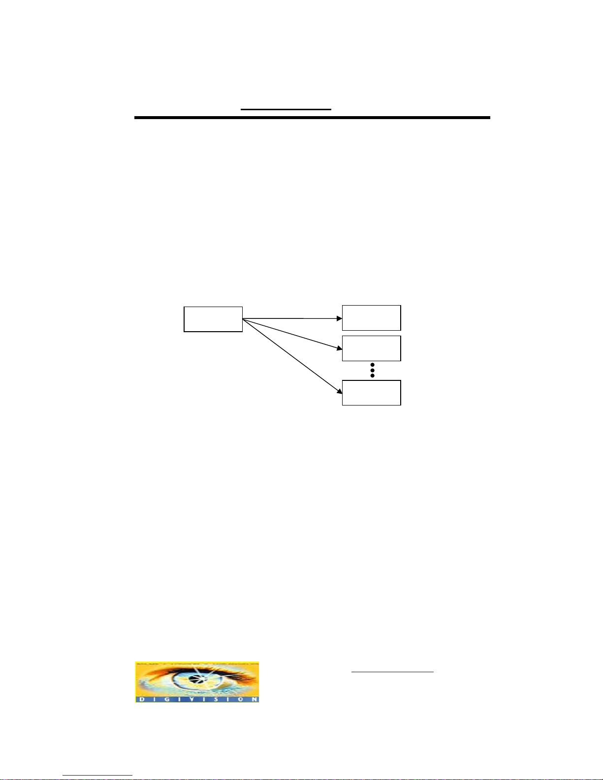
1:N Connection (Unidirection)
In this configuration, a site can be monitored from many remote center locations.
Although up to 64 decoders can be connected to on encoder, in the real network
environment, network bandwidth can limit the maximum connections.
Functionally, the central monitoring system software can replace the decoder.
Multicast Mode
Within the network that supports multicasting, a large number of decoders can be used
to receive video effectively from an encoder using a single streaming of vi deo and au dio.
Encoder
Decoder
Decoder
Decoder
Remote Center
Site
www.digivision.it StreamerH264 User Manual
Distributore per l’Italia : http://www.digivision.it
_
DIGIVISION srl - Viale Piave 3 - 20129 MILANO Italy
telefono ++39 02 7600 7932 - fax ++39 02 7601 6305
Ufficio vendite e-mail : vendite@digivision.it
-13-
Relaying
In this arrangement, video and audio can be retransmitted from a center to another
center. The arrangement is useful when the network bandwidth to the site is limited
while there are more than one center wanting to monitor the site.
Central Monitoring System
CMS (Central Monitoring System) is a Windows based remote monitoring program to
access multiple encoders for real-time monitoring or control of the encoders and
connected cameras. Please refer to CMS User Manual for more information on CMS.
Encoder Decoder
Site
Remote Center
Encoder
CMS
Encoder Decoder
Site
Center 1
Decoder
Center 2
CMS
Site
Remote Center

www.digivision.it StreamerH264 User Manual
Distributore per l’Italia : http://www.digivision.it
_
DIGIVISION srl - Viale Piave 3 - 20129 MILANO Italy
telefono ++39 02 7600 7932 - fax ++39 02 7601 6305
Ufficio vendite e-mail : vendite@digivision.it
-14-
2. Installation
1. Connecting Video
Encoder System
- Connect camera video output line to the encoder (STREAMERH264) video
input port.
Decoder System
- Connect monitor video input line to the decoder (STREAMERH264) video
output port.
Duplex System
- Connect camera video output line to the encoder (STREAMERH264) video
input port and connect monitor video input line to the decoder
(STREAMERH264) video output port.
2. Connecting Audio
Audio is bi-directional in any configuration regardless of the system mode. If necessary,
it can be configured to be in transmit-only, receive -only or bi-directional mode.
- Connect audio input and output ports to audio devices accordingly.
- Audio signal is in line level, therefore, microphone or speaker with amplification
function should be used.
3. Connecting Serial Ports
For camera control, PTZ controller(keypboard) and receiver can be connected to serial

www.digivision.it StreamerH264 User Manual
Distributore per l’Italia : http://www.digivision.it
_
DIGIVISION srl - Viale Piave 3 - 20129 MILANO Italy
telefono ++39 02 7600 7932 - fax ++39 02 7601 6305
Ufficio vendite e-mail : vendite@digivision.it
-15-
ports. Two corresponding serial ports in encoder and decoder which are connected in
connected in 1-to-1 fashion works in pass-through mode. This means that commands
at a local system’s COM1 port will be transparently passed to the remote system’s
COM1 port. Also, a command at a local system COM2 port will pass to the remote
system’s COM2 port.
4. Connecting Sensor and Alarm
Connect sensor and alarm devices to corresponding terminals accordingly.
5. Connecting Power
After confirming the power source, connect power adaptor and connect the 12VDC
connector to the system. Soon the system will boot up to an operating mode.
6. Check if It Works
As soon as the power is supplied to the system, it will boot and, after about 30 seconds,
the system will be ready for operation. Depending on the model of the system, the LED
display may be different as the system is running.
Encoder LED Display
Above LED status display shows that neither camera is connected nor a decoder is
connected. Once the encoder is connected to a decoder, color of link LED will light in
PWR
STATUS
LINK DATA
OFF
Red
Green
Blinking
OFF

www.digivision.it StreamerH264 User Manual
Distributore per l’Italia : http://www.digivision.it
_
DIGIVISION srl - Viale Piave 3 - 20129 MILANO Italy
telefono ++39 02 7600 7932 - fax ++39 02 7601 6305
Ufficio vendite e-mail : vendite@digivision.it
-16-
green color and the LED will blink as video or audio transmissions occur.
Decoder LED Display
Above LED status display shows that the encoder has started without connecting to a n
encoder. Once an encoder is connected, the color of link LED will be changed to green
and the LED will blink as video or audio data transmissions occur.
Duplex LED Display
Above LED status displays shows that duplex system has correct camera input but it is
not connected to another duplex system. Once a duplex system is connected, the color
of the link LED will change to green and the LED will blink as video or audio data
transmissions occur.
PWR
STATUS
LINK
Red
Green
Blinking
DATA
OFF
PWR
STATUS
LINK
Red
Green
Blinking
DATA
OFF
Red
Blinking
Red
Blinking
www.digivision.it StreamerH264 User Manual
Distributore per l’Italia : http://www.digivision.it
_
DIGIVISION srl - Viale Piave 3 - 20129 MILANO Italy
telefono ++39 02 7600 7932 - fax ++39 02 7601 6305
Ufficio vendite e-mail : vendite@digivision.it
-17-
3. System Operation
1. LED Display
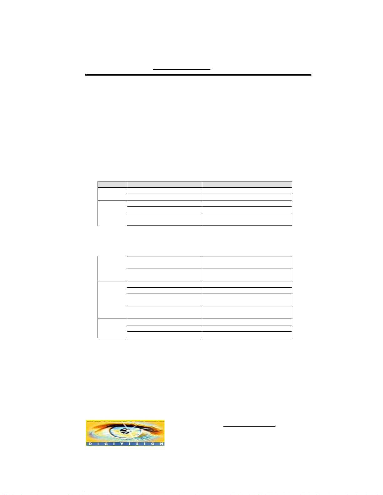
Description of LEDs
System status can be monitored with LEDs.
LED State Description
Off No power
PWR
Red Power on
Green blinking Normally operating
Red System failure: Needs diagnostics
Constant change of colors
between Red and Green
NTSC/PAL setting does not match
with input video signal
Red Blinking Failed to obtain IP address in
DHCP mode or PPPoE mode
Constant change of colors
between Green blinking 2
times and Red blinking once
Failed to register on DDNS server
Green blinking, Red blinks
once every 5 seconds
Video loss in Encoder system
STATUS
Orange blinking Improper resolution setting in
duplex mode
Off No connection to remote system
Green Connected to a remote system
Red blinking Decoder only: trying to connect to
an Encoder
LINK
Orange Illegal connection (unsupported
combination of system modes)
Green Data transmission in progress
Red Data loss
DATA
Off No data transmission
2. Remote Video Monitoring

www.digivision.it StreamerH264 User Manual
Distributore per l’Italia : http://www.digivision.it
_
DIGIVISION srl - Viale Piave 3 - 20129 MILANO Italy
telefono ++39 02 7600 7932 - fax ++39 02 7601 6305
Ufficio vendite e-mail : vendite@digivision.it
-18-
There are two ways to view the video once connections are made between the site and
center system. In order for a proper operation, an IP address must be set accordingly
and please refer to True Manager in Chapter 4 or Remote Setting in Chapter 5 for a
further details.
Video Monitoring with Decoder System
Once the encoder IP address is set in the remote IP address section of the decoder, the
decoder system will connect to the encoder system and start receiving the video images.
Normally, a monitor connected to the decoder will display video images.
Video Monitoring using Internet Explorer
If an encoder’s IP address in entered on the Internet Explorer, the system will ask for
confirmation to install Active-X control. Once authorized, the Internet Explorer will start
to display video images from the encoder as shown below.
http://192.168.10.100
 Loading...