

Page 1

TE400 Series
TE420B/TE420/412P/410P/407P/405P
User Manual
Release 1.0
Page 2

150 West Park Loop, Suite 100
Digium, Inc.
Huntsvil le, AL 35806
United States
Main Number: 1.256. 428.6000
Tech Support : 1.256.428.6161
U.S. Toll Free: 1.877.546.8963
Sales: 1.256.428.6262
www.digium.com
www.asterisk.org
www.asterisknow.org
© Digium, Inc. 2007
All rights reserved.
No part of this publication may be copied, distributed, transmitted, transcribed, stored in a
retri eval syst em , or t ran sl ated int o any huma n or compu te r lan gu ag e with ou t t he pr io r wri tte n
permission of Digium, Inc.
Digium, Inc. has made every effort to ensure that the instructions contained in this document
are ade q u a te an d error free. The manu facture r w i ll, if ne c es s ary , explai n issues w h ic h m ay
not be covered by this documentation. The manufacturer’s liability for any errors in the
docume nts is limi ted to the correctio n of errors and the aforementioned advis ory services.
This doc ument has been prepar ed for us e by profe ssiona l and pr operly tr ained personn el,
and the cus to m er as su m es full respon si bi lity when us in g it.
Adobe and Acrobat are registered trademarks, and Acrobat Reader is a trademark of Adobe
Systems Incorporated.
Asteri sk and D igi um a r e re gi ster e d tr ad emar ks and Ast eri sk B usi ne ss Ed it i on, A st eri sk NOW,
AsteriskGUI, and Asterisk Appliance are trademarks of Digium, Inc.
Any other trademarks mentioned in the document are the property of their respective owners.
Release 1.0 Digium, Inc. Page 2
Page 3

Safety Certificati on and Agency Approvals
Safety:
UL 60950-1:2003, First Edition
CSA C22.2 No. 60950-1-03 1st Ed. April 1, 2003
IEC 60950-1:2001 First Edition
EN 60950
AS/NZS 60950
Note: Finland, Norway and Sweden require that equipment using this
product must be located in a Restric ted Access Location (RAL).
Telecom:
FCC Part 68, ANSI/ITA-968-A, Including Amendment A1 and A2
Industry Canada CS-03
AS/ACIF S016: 2001
AS/ACIF S038: 2001
ICASA (TE405P/TE407P/TE410P/TE412P)
RosTest
TBR4 November 1995 as amended by TBR4/A1 December 1997
TBR12 December 1993
TBR13 January 1996
Emissions:
Note: Shielded T1/E1/J1 cables are required for compliance purp oses.
47 CFR Part 15, Subpart B / 47 CFR Part 15, Subpart B, Class B
EN 55022:1998 Class B / EN 55022:1998 Class B Radiated and
Conducted
EN 55024:1998 / IEC 61000
Release 1.0 Digium, Inc. Page 3
Page 4

Immunity:
EN55024 ITE, EN61000
Federal Communications Commission Part 68
This equipment complies with Part 68 of the FCC rules and the
requirements adopted by the ACTA. On the back of the TE 400 Series
printed circuit board is a label tha t contains, among other information, a
product identifier in the format US:AAAEQ##TXXXX. If requested, this
number must be provided to the telephone compa ny.
A plug and jack used to connect this equipment to the premi ses wiring
and telephone network must comply with the applicable FCC Part 68
rules and requirements adopted by the ACTA.
If the TE 400 Series causes harm to the telephone network, the telephone
company may notify you in advance that temporary discontinuance of
service may be required. But if advance notice is not practical, the
telephone company will noti fy you as soon as possible. Also, you will be
advised of your right to file a complaint with the FCC if you believe it is
necessary.
The telephone company may make changes in its facilities, equipment,
operations or procedures that could a ffect the operation of the equipment.
If this happens, the telephone company will provide advance notice in
order for you to make necessary modifications to maintain uninterrupted
service.
If you experience problems with the TE 400 Series, contact Digium, Inc.
(+1.256.428.6161) for repair and/or warranty information. If the
equipment is causing harm to the telephone network, the telephone
Release 1.0 Digium, Inc. Page 4
Page 5

company may request that you disconnect the equipment until the
problem is resolved.
FCC Part 15
This device complies with part 15 of FCC rules. Operation is subject to
the following two conditions: (1) This device may not cause harmful
interferen ce, and (2) T h is dev ice mu s t accep t any in terference receiv ed,
including interf erence that may cause undesired operation.
Industry Canada Compliance Information
Notice: The Industry Canada label applied to the product (identified by
the Industry Canada logo or the "IC:" in f ront of the certification/
registration number) indicates that the Industry Canada technical
specifications were met.
Release 1.0 Digium, Inc. Page 5
Page 6

Introduction to TE 400 Series Documentation
This manual is a user guide for Digium’s TE 400 Series cards. The
Digium TE 400 Series cards are a T1/E1 capable card series created for
voice and data. The car d s in this se ri es are as follo w s:
Table 1: TE400 Series Cards
Model Features Type
TE420B
TE420
TE412P
TE410P
TE407P
TE405P
Release 1.0 Digium, Inc. Page 6
3.3 volt, 4 Ports, Echo Cancellation
3.3 volt, 4 Ports
3.3 volt, 4 Ports, Echo Cancellation
3.3 volt, 4 Ports
5.0 volt, 4 Ports, Echo Cancellation
5.0 volt, 4 Ports
PCI Express
PCI Express
PCI 2.2
PCI 2.2
PCI 2.2
PCI 2.2
Page 7

Document Organization
The TE400 Series user’s guide is organized in the following manner:
Chapter/
Appendix
1
2
3
4
A
B
C
Title Description
Overview Identifies the features of the card you received. This
chapter covers applications and uses of the TE 40 0
Series cards i n the real world.
Card Installation Provides instructions for installing the card in your
PC, acquiring correct drivers, and checking device
compatibility.
Configuration Provides examples for configuring dial plan options.
Troublesh ooting Expla ins resolutio ns to common problems and
frequentl y as ked questions per taining to card
installation and usage.
Pin Assignments Lists the connectors and pin assignments .
Specifications Details card specifications.
Glossary and
Acronyms
Defines terms related to this product.
Release 1.0 Digium, Inc. Page 7
Page 8

Symbol Definitions
Caution stat emen ts in dicate a c onditio n whe r e d amage to t he un it o r
its configuration could occur if operational procedures are not
followed. To reduce the risk of damage or injury, follow all steps or
procedures as instructed.
The ESD sym b o l in d i ca t es electrostat i c sen s i ti ve de vi ce s . O b serve
prec autions for handling devi ces. Wear a proper ly grounded
electrostatic discha rge (ESD) wrist strap while handling the device.
The Electrical Hazard Symbol indicates a possibility of electrical
shock when operat ing this unit in certain situations. To reduce the
risk of damage or injury, fol low all steps or proc edures as
instructed.
Release 1.0 Digium, Inc. Page 8
Page 9

User Cautions
Servicing.
Do not attempt to service this card unless specifically instructed to do
so. Do not attempt to remove the card from your equipment while
power is present. Refe r ser vicing to qualified service personnel.
Water and Moisture.
Do not spill liquids on this unit. Do not operate this equipment in a
wet environme nt.
Heat.
Do not operate or store this product near heat sources such as
radiators, air ducts, areas subject to direct, intense sunlight, or other
products that produce heat.
Static Electricity.
To reduce the risk of damaging the unit or your equipment, do not
attempt to open the enclosur e or gain acc es s to areas where you ar e
not instructed to do so. Refer servicing to qualified service personnel.
Save these instructions for future reference.
Important Safety Instructions
Release 1.0 Digium, Inc. Page 9
Page 10

TABLE OF CONTENTS
Chapter 1
Overview . . . . . . . . . . . . . . . . . . . . . . . . . . . . . . . . . . . . . . . . . . . . . . .14
What is Asterisk?. . . . . . . . . . . . . . . . . . . . . . . . . . . . . . . . . . . . . . .19
Chapter 2
Card Installation . . . . . . . . . . . . . . . . . . . . . . . . . . . . . . . . . . . . . . . . . 20
Unpacking the Card . . . . . . . . . . . . . . . . . . . . . . . . . . . . . . . . . . . .21
Identifying Communication Ports . . . . . . . . . . . . . . . . . . . . . . . . . .22
T1/E1 Selection . . . . . . . . . . . . . . . . . . . . . . . . . . . . . . . . . . . . . . .24
Identifying Multiple Cards . . . . . . . . . . . . . . . . . . . . . . . . . . . . . . . .24
Connecting Timing Cables . . . . . . . . . . . . . . . . . . . . . . . . . . . . . . .25
PCI Slot Compatibility . . . . . . . . . . . . . . . . . . . . . . . . . . . . . . . . . . .27
Hardware Installation . . . . . . . . . . . . . . . . . . . . . . . . . . . . . . . . . . . 29
Software Installation . . . . . . . . . . . . . . . . . . . . . . . . . . . . . . . . . . . .30
Chapter 3
Configuration . . . . . . . . . . . . . . . . . . . . . . . . . . . . . . . . . . . . . . . . . . . .34
Configuring T1/E1 Lines . . . . . . . . . . . . . . . . . . . . . . . . . . . . . . . . .34
Testing Your configuration. . . . . . . . . . . . . . . . . . . . . . . . . . . . . . . .41
Chapter 4
Troubleshooting . . . . . . . . . . . . . . . . . . . . . . . . . . . . . . . . . . . . . . . . .43
Appendix A
Pin Assignments . . . . . . . . . . . . . . . . . . . . . . . . . . . . . . . . . . . . . . . . .49
Release 1.0 Digium, Inc. Page 10
Page 11

Table Of Contents
Appendix B
Specifications . . . . . . . . . . . . . . . . . . . . . . . . . . . . . . . . . . . . . . . . . . .5 0
Appendix C
Glossary and Acronyms . . . . . . . . . . . . . . . . . . . . . . . . . . . . . . . . . . .5 2
Release 1.0 Digium, Inc. Page 11
Page 12

List of Figures
Figure 1: Sample Legacy Phone Application . . . . . . . . . . . . . .16
Figure 2: Sample Channel Bank Application . . . . . . . . . . . . . .17
Figure 3: Sample IP Phone Application . . . . . . . . . . . . . . . . . .18
Figure 4: TE405P Card . . . . . . . . . . . . . . . . . . . . . . . . . . . . . .22
Figure 5: TE420 Card . . . . . . . . . . . . . . . . . . . . . . . . . . . . . . .23
Figure 6: T1/E1 Jumpers . . . . . . . . . . . . . . . . . . . . . . . . . . . . .24
Figure 7: Ident Wheel . . . . . . . . . . . . . . . . . . . . . . . . . . . . . . . .25
Figure 8: Timing Ports . . . . . . . . . . . . . . . . . . . . . . . . . . . . . . .26
Figure 9: Motherboard PCI Slots . . . . . . . . . . . . . . . . . . . . . . .27
Figure 10: Insert the Card . . . . . . . . . . . . . . . . . . . . . . . . . . . . .29
Figure 11: dmesg Screen Capture . . . . . . . . . . . . . . . . . . . . . . . 41
Release 1.0 Digium, Inc. Page 12
Page 13

List of Tab le s
Table 1: TE400 Series Cards . . . . . . . . . . . . . . . . . . . . . . . 6
Table A-1: RJ45 Telco Port Connector . . . . . . . . . . . . . . . . . . . .49
Table B-2: Maximum Power Consumption . . . . . . . . . . . . . . . . .51
Release 1.0 Digium, Inc. Page 13
Page 14

Chapter 1 Overview
The Digium TE 400 Series cards are a T1/E1 capable card series created
for voice and data. They support industry standard protocols, including
Robbed Bit Signaling, E&M, Primary Rate ISDN (PRI), and several data
modes (PPP, HDLC, Cisco HDLC and frame relay). The TE400 Series
are capable of running in E1, T1, or J1 modes. They are also capable of
DACSing channels f rom one span to another . The TE 400 S eries are ideal
for connecting phones to a channel bank, connec ting to your T1/E1
switch, or connecting to a legacy PBX.
This manual is for use with the TE420/TE420B PCI Express car d, as well
as the 5 volt TE405P/407P and the 3.3 volt TE410P/412P Quad T1/E1
PCI cards. These cards are identified collectively as the TE 400 Series
cards throughout this manual.
Designed to be fully compatible with existing software applications and
integrate fully with Asteris k Open Source PBX/I VR platform, the TE 400
Series cards allow many advanced call fea tures.
Data Modes:
Cisco HDLC
HDLC
PPP
Multilink PPP
Frame Relay
Release 1.0 Digium, Inc. Page 14
Page 15

Voice Modes:
PRI CPE and PRI NET
– NI1
– NI2
– EuroISDN
– 4ESS (AT&T)
– 5ESS (Lucent)
– DMS100
E&M
– Wink
– Feature Group B
– Feature Group D
FXO and FXS
– Ground Start
– Loop Start
– Loop Start with Disconn ect Detect
Chapter 1: Overview
The TE 400 Series cards can be used to connect your Asterisk machine to
the PSTN world, your channel bank, or even another PBX. This is
accomplished via a T1/E1 interface. The cards allow Asterisk software to
connect to your network, creating a professional telephony environment.
Figure 2 shows an example of the card’s primary application.
Release 1.0 Digium, Inc. Page 15
Page 16
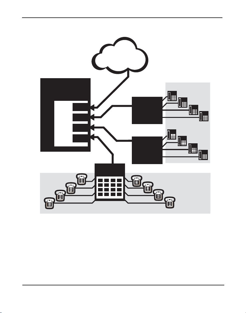
CLEC
Chapter 1: Overview
Asterisk
Server
TE4xx
Figure 1: Sample Legacy Phone Application
T1
T1
T1
Channel
Bank
PRI
Legacy
PBX
Legacy
Phones
Legacy
PBX
Analog
Phones
Release 1.0 Digium, Inc. Page 16
Page 17
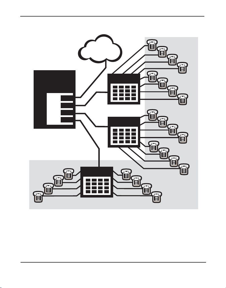
CLEC
Asterisk
Server
TE4xx
Analog
Phones
PRI
T1
T1
T1
Channel Bank
Channel Bank
Channel Bank
Chapter 1: Overview
Figure 2: Sample Channel Bank Application
Release 1.0 Digium, Inc. Page 17
Page 18
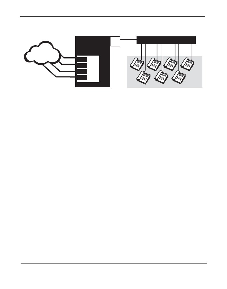
Chapter 1: Overview
CLEC
ASTERISK
SERVER
TE4xx
Switch
Eth
LAN
IP
Phones
PRI
T1
PRI
T1
Figure 3: Sample IP Phone Application
Release 1.0 Digium, Inc. Page 18
Page 19

Chapter 1: Overview
What is Asterisk?
Asterisk is the first open -source telephony platform. Since it runs on
Linux, it inherits all of the power and stability of that operating system.
The name Asteri sk is derived from the all-inclusive “wildcard” symbol i n
UNIX. It is representative of the wide range of opportunities it opens for
developers worldwide to create solutions which would otherwise be costprohibitive.
Asterisk allows you to create a PBX solution that rivals the features and
functionality of traditi ona l telephony swi tc hes. Current P BX soluti ons are
expensive and proprieta ry. International companies are discover ing that
Asterisk is cost ef fectiv e, low mainte nanc e, and flexibl e enough to handle
all of their voice and data networking. Combined with Digium hardware
and a common PC, anyone can replace an existing switch or complement
a PBX by adding VoIP, voicemail, confer encing, and many other
capabilities . Aste risk will integrate with most standards- based IP
telephone handsets and softwa re. Analog phones and ADSI-screen
phones are also supported.
Release 1.0 Digium, Inc. Page 19
Page 20

Chapter 2 Card Installation
This chapter provides the following information:
Unpacking the Card on page 21
Identifyi ng C om m un ic a tion Por ts on page 22
T1/E1 Selection on page 24
Identifying Multiple Cards on page 24
Connecting Timing Cables on page 25
PCI Slot Compatibility on page 27
Hardware Installat ion on page 29
Software Installation on page 30
Note: The TE400 Series card installation instructions are written so
that they will apply to any card in the series. Examples and card
specific inf ormation are included as need ed .
Release 1.0 Digium, Inc. Page 20
Page 21

Chapte r 2: C ar d In st a lla tion
Unpacking the Card
When you unpack your card, carefully inspect it for any damage that may
have occurred in shipment. If damage is suspected, file a claim with the
carrier and contact your reseller from which the card was purchased, or
Digium T ec hnical Support (+1. 256.428. 6161). Keep the origina l shi pping
container to use for future shipment or proof of damage during shipment.
Note: Only qualified service personnel should install the card. Users
should not attempt to perform thi s function themselves.
Shipment Inspection
The following items are includ ed in shipment of the TE400 Series:
TE400 Series card (TE405P/407P/ 410P/412P/420/420B)
Release 1.0 Digium, Inc. Page 21
Page 22

Chapte r 2: C ar d In st a lla tion
Ports
1
2
3
4
Ident
Wheel
PCI 2.2
Connector
Jumpers
Timing
Port
Status
LEDs
Identifying Communication Ports
The TE400 Seri es cards consists of four RJ45 ports and four status LEDs.
The ports are used for connecting T1, E1, or J1 cables. Refer to Figure 4
on page 22 or Figure 5 on page 23 to locate the ports and LEDs.
Figure 4: TE405P Card
Release 1.0 Digium, Inc. Page 22
Page 23

Ports
1
2
3
4
Status
LEDs
Jumpers
Ident
Wheel
PCI Express
Connector
Timing
Port
Chapte r 2: C ar d In st a lla tion
Figure 5: TE420 Card
Release 1.0 Digium, Inc. Page 23
Page 24

Chapte r 2: C ar d In st a lla tion
T1/E1 Selection
The card includes a row of jumpers to select either T1 or E1 mode for the
spans. An exam p le of the jum pe rs fro m the TE 405 car d is sh own i n
Figure 6. The T1/E1 mode, in most cases, is set at the distributor before
shipment. You may want to check the setting to be certain they are set for
your specific use.
Figure 6: T1/E1 Jumpers
Identifying Multip le Cards
If multiple TE400 Series cards are insta lled in the same machine, then the
Ident wheel can be used to control the or der the ca rds are recognize d. The
click wheel switch with the word Ident printed above it can be set to a
different num ber for each installed card. This number adjusts the order in
which the drive r recognizes the card. For example: set the first card Ident
wheel to 0, set the sec ond card Ident wheel to 1, and so on. The Ident
wheel is shown in Figure 7.
Release 1.0 Digium, Inc. Page 24
Page 25

Chapte r 2: C ar d In st a lla tion
Figure 7: Ident Wheel
Connecting Timing Cables
The timing por t allow s up to four TE 4 00 Se rie s card s to share the sa me
sync (timing) source from the T1 line provider, or provide a consistent
sync source across multipl e cards. This is a useful fea ture for data and fax
modes and some voice applications to prevent corruption due to timing
slips on the second, third or fourth TE400 Series PC cards.
T o utilize this feature, dai sy-chain the P1 connector between each TE400
Series card using the Digium 4-posi tion timing cable. See Figure 8 on
page 26 for an example. Enable this featur e in the drivers using the
timingcable=1 switch when the drivers are loaded:
# modprobe wct4xxp timingcable=1
Release 1.0 Digium, Inc. Page 25
Page 26

Chapte r 2: C ar d In st a lla tion
Figure 8: Timing Ports
Caution.
Only qualified service personnel should continue with
hardware installation and confi guration of the TE400 Series
card. Use rs should not attempt to pe rform these functions
themselves.
Release 1.0 Digium, Inc. Page 26
Page 27

Chapte r 2: C ar d In st a lla tion
0
1
2
3
4
Slots
PCI Slot Comp at ib i li ty
Check the type of card you received to be sure it is compatible with your
PCI slot. To determine which slot you have, identify it by comparing it to
those shown in Figure 9 on page 27.
Slot Number:
0: AGP Pro Slot
1: 64-bit 5.0 volt PCI Slot
2: 64-bit 3.3 volt PCI Slot
3: 32-bit 5.0 volt PCI Slot
4: PCI Express Slot
Figure 9: Motherboard PCI Slots
Release 1.0 Digium, Inc. Page 27
Page 28

Chapte r 2: C ar d In st a lla tion
The TE405P/407P card is a 32-bit 33MHz card keyed for 5.0 volt
operation and works in any PCI 2.2 (or higher) compliant slot which
supports 5.0 volts. This means that in the motherboard shown in Fi gure 9,
the TE405P/407P card will fit into Slots 1 and 3. The TE405P/407P will
not fit into Slot 2.
The TE410P/412P card is a 32-bit 33MHz card keyed for 3.3 volt
operation and works in any PCI 2.2 (or higher) compliant slot which
supports 3.3 volts. This means that in the motherboard shown in Fi gure 9,
the TE410P/412P card will only fit into Sl ot 2. The TE410P/412P will
not fit into Slots 1 or 3.
The TE420/TE420B card is a PCI Express card. Slot 4, ill ustrated above,
is a 1 lane (X1) PCI Express compliant slot. The TE420/TE420B will
work in any PCI Express compliant slot, including lane lengths X4, X8,
and X16. This means that in the motherboard shown in Figure 9, the
TE420/TE420B will only fit into Slot 4. The TE420 can not be used in
Slots 1 through 3.
Release 1.0 Digium, Inc. Page 28
Page 29

Chapte r 2: C ar d In st a lla tion
Hardware Installat ion
1. Now that you are acquainted with the cards , power down your
computer and unplug it from its power sourc e.
2. Attach a static strap to your wrist a nd open the case .
3. Check the jumper setting to ensure it matches your equipment
configuration. Setting the jumper with the switch on enabl es the ports
for E1. Setting the jumper with the switch off enables the port s for T 1.
4. Remove the bracket place holder and insert the card into the PCI or
PCI Express slot. See Figure 10 for an example of card installation.
Figure 10: Insert th e C ar d
5. Replace the cover to your computer.
6. Plug all T1 or E1 equipment cables into the RJ45 ports as needed.
Note: It is recommended that you use shielded cables.
Release 1.0 Digium, Inc. Page 29
Page 30

Chapte r 2: C ar d In st a lla tion
Caution.
This unit must be connected to the Teleco mmu nications
Network in your country using an approved line cord, e.g.: for
Australia use only line cords complying with ACA Technical
Standard TS008.
Caution.
This unit must be connected only to the appr opriate
Telecommunications Network por t (as approved for use in your
specific country).
Softw a r e In s t al la t io n
The card is only supported under Linux. Digium, Inc. recommends
Debian, Fedora, and Red Hat, however, all other distributions are
supported by Digium Technical Support. Digium hardware requires
drivers and librarie s that are integrated with the Linux kernel. You can
obtain the source code from ftp.digium.com
. Detailed instructions are
provided in this section .
T o install software for your TE400 Series card, you will need:
Full Linux kernel 2.6 (or later) sour ce code.
Development librarie s and head ers for libncurses (only necessary for
Asterisk).
Development librarie s and head ers for zlib and openssl.
If you are using the 1.2.x series of Aste risk and Zaptel, you will need
Asterisk 1.2.18 or newer, and Zaptel 1.2.18 or newer. If you are using
the 1.4.x series of Asterisk and Zaptel, you will need Asterisk 1.4.4 or
newer and Zaptel 1.4.3 or newer. If you are using Asterisk Business
Edition, you will need version B. 2 or newer.
Release 1.0 Digium, Inc. Page 30
Page 31

Chapte r 2: C ar d In st a lla tion
1. Check your lspci PCI device listing. Boot the computer into Linux.
After the machine has loaded, log in and execut e the following:
# lspci -n
Confirm your lspci PCI device listing by scanning f or the following
information in the output screen:
0000:01:0e.0 ISDN controller: Unknown device
d161:<card identifier>
In the device listing shown above, <card identifier> will be populated
with one of the identifiers listed in the table below.
Table 1: Card Identifiers
Model Identifier
TE420B
TE420
TE412P
TE410P
TE407P
TE405P
0420
0420
0410
0410
0405
0405
A Digium TE400 Series (TE420B/TE420/412P/410P/407P/405P)
ISDN Controller should be identi fied. If a controller is not identified,
then your machine is not PCI 2.2 (or higher) or PCI Express
compatible and the card will not work with your equipment.
Release 1.0 Digium, Inc. Page 31
Page 32

Chapte r 2: C ar d In st a lla tion
2. Download the latest Zaptel drivers (1.2.17 or later) to your /usr/src
directory. The Zaptel drivers can be downloaded using either ftp or
http. They are accessible via ftp from ftp://ftp.digum.com/pub/zaptel.
They are acces sibl e v ia http fro m http://ftp.digium.com/pub/zaptel/.
The following example is one way that you could download the
drivers to your /usr/src directory:
# wget http://ftp.digium.com/pub/zaptel/zaptel-1.X.X.tar.gz
where the X.X stands for the version of Zaptel you are downloading.
3. Expand the downloaded tarball an d insta ll the drivers:
#cd /usr/src
#tar -zxvf zaptel-1.X.X.tar.gz
#cd zaptel-1.X.X
#make clean
#./configure (applies to 1.4.X only)
#make menuselect (applies to 1.4.X only if you wish
to customize the install)
#make
#make install
Note: If you don’t already have configuration files installed, you can
type make samples to install the default sample configuration files.
Release 1.0 Digium, Inc. Page 32
Page 33

Chapte r 2: C ar d In st a lla tion
4. Downloa d the latest released vers io n of As te risk (1 .2. 1 8 or late r).
Asterisk can be downloaded using ftp or http. It is accessible via ftp
from ftp://ftp.digum.com/pub/asterisk. It is also accessible via http
from http://ftp.digium.com/pub/asterisk. The following ex ample is one
way that you could download the drivers to your /usr/src directory:
# wget http://ftp.digium.com/pub/zaptel/
asterisk-1.X.X.tar.gz
where the X.X stands for the ve rsion of Aste risk you are downloa ding.
5. Expand the downloaded tarballs. Substitute the version of Asterisk
you are using with the XX in the command lines below.
# tar -zxvf asterisk-1.2.xx.tar.gz
# cd asterisk-1.2.xx/
# make
# make install
If the build fails, it may be because you are missing one of the build
dependencies, the kernel source, or development tools. Feel free to
contact your res e ller wher e the card was purchas ed, or call Digi um
Technical Support (+1.256.428.6161) for assistance.
Note: Complete instructions for installing Asteri sk are available at
www.asterisk.org
Release 1.0 Digium, Inc. Page 33
.
Page 34

Chapter 3 Configuration
The TE400 Series cards have a variety of configuration options. This
chapter provides confi gurations for PRI, channel bank, E&M wink, and
finally, data mode. These sample configur ations are pr ovi ded to assi st y ou
in familiarizing yourself with the flexibility of editing the configuration
files to meet your specific needs. The list of possibl e configur ations is too
expansive to cover in this user manual.
Configuring T1/E1 Lines
1. Begin by opening the zaptel.conf file from the /etc/asterisk/
directory.
2. Configure the SPAN Map.
For each T1/E1 you are using you will need to define a span. The
SPAN map includes defini ng the SPAN number, t iming, li ne build out ,
framing and coding. Configuration details for each of these items is
explained in this section.
span => NUMBER,TIMING,LINE BUILD OUT,FRAMING,CODING
Number:
This is the port the spa n is plugged into. Port 1 being the furthest span
from the PCI bus . Th e por t num ber s are not ed on the PCI bracket.
Release 1.0 Digium, Inc. Page 34
Page 35

Chapter 3: Configuration
Timing:
Determines whether the card provides timing (0), takes timing (1),
takes backup span timing (2), provides backup span timing (3), and so
on. Only one span can be defined to take timing and it defines timing
for the rest of the card s pan s .
Line Build Out
For most setups the line build out is 0.
0: 0 db (CSU) / 0-133 feet (DSX-1)
1: 133-266 feet (DSX-1)
2: 266-399 feet (DSX-1)
3: 399-533 feet (DSX-1)
4: 533-655 feet (DSX-1)
5: -7.5db (CSU)
6: -15db (CSU)
7: -22.5db (CSU)
Framing
T1 utilizes framing set for D4 (SF) or ESF. E1 utilizes CAS or CCS.
Coding
T1 coding can be AMI or B8ZS. E1 coding can be AMI or HDB3. E1
can also have the extra flag CRC4 at the end for CRC4 checking.
Yellow flag can also be added at the end for transmitting a yellow
alarm when all channels are in use.
Release 1.0 Digium, Inc. Page 35
Page 36

Chapter 3: Configuration
The following is a typical setup for a telco in the US:
span => 1,1,0,esf,b8zs
In Europe:
span=>1,1,0,ccs,hdb3
First Example: Channel Bank
The Channel Bank in this example has 24 FXS ports. In this
configuration, the
zaptel.conf is set for the card to provide timing to the
channel bank and fxoks is set for 24 stations.
zapata.conf to mirror the configur ation with signalling=fxo_ks
Set
and define it for channels 1-24.
/etc/zaptel.conf:
span=1,0,0,esf,b8zs
fxoks=1-24
/etc/asterisk/zapata.conf:
group=1
context=channelbank
signalling=fxo_ks
channel=1-24
Release 1.0 Digium, Inc. Page 36
Page 37

Chapter 3: Configuration
Second Example: E&M Line
In the E&M Line configur ation, the zaptel.conf is set for the card to take
timing from the telco on E&M with wink while zapata.conf mirrors the
configuration. However, Fea t_D is a type of E&M with wink that accepts
DID, but there are many E&M options; E&M_W, E&M, Feat_B, etc.
/etc/zaptel.conf:
span=1,1,o,esf,b8zs
e&m=1-24
/etc/asterisk/zapata.conf:
group=1
context=incoming
signalling=feat_d
channel=1-24
Third Example: PRI
By setting the card to take timing in zaptel.conf, you acquire 23 b
channels and voice channels, with channel 24 as the data transport. For
Asterisk, define PRI_CPE so it is the client side. Define the switch type
you are connecting to as national. There are several opti ons for the swi tch
type including 5ESS, 4ESS, and NI1. You will then have 23 voice
channels fo r Asteri s k.
Release 1.0 Digium, Inc. Page 37
Page 38

PRI T1
/etc/zaptel.conf:
span=1,1,0,esf,b8zs
bchan=1-23
dchan=24
/etc/asterisk/zapata.conf
group=1
signalling=pri_cpe
switchtype=national
context=incoming
channel=1-23
PRI E1
/etc/zaptel.conf:
span=1,1,0,ccs,hdb
bchan=1-15,17-31
dchan=16
Chapter 3: Configuration
/etc/asterisk/zapata.conf
group=1
signalling=pri_cpe
switchtype=euroisdn
context=incoming
channel=1-15,17-31
Release 1.0 Digium, Inc. Page 38
Page 39

Chapter 3: Configuration
Fourth Example: Data Mode
Data mode is a little different than the other options. The zaptel.conf is
configured as follows:
/etc/zaptel.conf
span=1,0,0,esf,b8zs
nethdlc=1-24
Instructions for Cisco HDLC:
1.
Compile kernel with HDLC support:
Note: We suggest that you use either a Kernel version of 2.4.20 or
less, or a Kernel of 2.6.8 or greater. The HDLC implementation in the
interval kernels is in a state of too much flux. The following data
modes are described in this section:
– WAN Interfaces Support
– Generic HDLC Layer
– Cisco HDLC support
2. Rebuild and reboot into your kernel.
3. Uncomment the followin g line in zconfig.h of the Zaptel pack age:
#define CONFIG_ZAPATA_NET
If you are using a kernel prior to 2.4.19, also uncomment this line:
#define CONFIG_OLD_HDLC_API
Release 1.0 Digium, Inc. Page 39
Page 40

Chapter 3: Configuration
Rebuild Zaptel including the creation of the SetHDLC utility:
make sethdlc-new;use "make sethdlc" for
;kernels 2.4.19 and prior
make install
4.
Load and configure your driver :
modprobe wct4xxp
ztcfg
5.
Use sethdlc to bring up the interface:
sethdlc hdlc0 cisco
-or- for old style (mak e sethdlc instead of sethdlc-new) use:
sethdlc hdlc0 mode cisco
6.
Assign the interface an address:
ifconfig hdlc0 192.168.0.1 netmask 255.255.255.0
7.
The interface may be addressed as any other networking interface
(i.e., eth0) in Linux.
Release 1.0 Digium, Inc. Page 40
Page 41

Chapter 3: Configuration
T esting Y our confi guration.
1. Load Zaptel drivers into the kerne l using the program modprobe. The
appropriate driver for the TE400 Series cards is
wct4xxp. Users in all
countries except Austra lia should use the following modprobe
command:
# modprobe wct4xxp
ztcfg -vv
dmesg screen import
Figure 11: dmesg Screen Capture
Note: Output as shown above may vary depending on the TE400
Series card you use.
Release 1.0 Digium, Inc. Page 41
Page 42

Chapter 3: Configuration
2. Run zttool from the command line and see if the span turns g reen for
each span you h ave co n nect ed.
zttool
Execute the follo w ing A ste ri sk command to see if the span came up
3.
successfully.
asterisk
asterisk -vvvr
Release 1.0 Digium, Inc. Page 42
Page 43

Chapter 4 Troubleshooting
This chapter provides frequently asked questions as identified from
Digium Technical Support and possible resolutions. Multiple resourc es
are available to obtain more infor mation about Asterisk and Digium
products. These resources are listed on page 48.
What do the LE D co lor s indicate?
Green - Card is in-sync with the far end.
Yellow - Card is synchronizing.
Red - Card is not seeing far end, circuit is not up, or cable is bad.
How do I identi fy wh i ch card I have using soft w are?
Check your
lspci PCI device listing. Boot the computer into Linux. After
the machine has loaded, log in and execute the fol lowing:
# lspci -n
Confirm your lspci PCI device listing by scanning f or the following
information in the output screen:
0000:01:0e.0 ISDN controller: Unknown device
d161:<card identifier>
In the device listing shown above, <card identifier> will be populated
with one of the identifiers listed in the table below.
Release 1.0 Digium, Inc. Page 43
Page 44

Chapter 4: Troubleshooting
Table 2: Card Identifiers
Model Identifier
TE420
TE412P
TE410P
TE407P
TE405P
0420
0412
0410
0407
0405
A Digium TE400 Series (TE420/412P/410P/ 407P/405P) ISDN
Controller should be ident ified. If a controller is not identified, then
your machine is not PCI 2. 2 (or highe r) or PCI Expr ess compatibl e and
the card is not working with your equipment.
I can't receive DID calls even though I have it enabled in
extensions.conf.
Your telco might be sending calls with a method you are not expecting.
1. Check the method being used by attempting the following in your line
context:
_x.,1,noop(My DID Matches as ${EXTEN}
2.
Then type reload in the Asterisk console and call in. You should see
the DID come in on your T1/E1 line.
Page 44 Digium, Inc. Release 1.0
Page 45

Chapter 4: Troubleshooting
My D Channel seems to go up and down.
Check to be sure you have set your timing parameters correctly. Also
check the common causes of problems for a T1. See the Common Fixes
for all cards , page 47.
I have trouble dialing out. It seems that one type of dialing works
(local, long distance, international) but another does not.
Check your
pridialplan variable and be sure that you a re di aling us ing the
method your telco is expecting .
I am having trouble receiving DID information over E&M.
Try the other types of E&M (featd, featb, etc.) to match the method your
telco is using to stream infor mation.
I am having issues with my PRI. How can I see the messages coming
across my D chan nel?
Enter the following command:
PRI debug span X
where x is the port from which you are connected. This command will
show you the PRI messages coming across your D channel for that
message.
Release 1.0 Digium, Inc. Page 45
Page 46

Chapter 4: Troubleshooting
I am still having problems and the telco tells me it is my equipment.
The first thing to do in this situat ion is to test your equipment.
1. Plug in a loopback cable. (A loopback cable is a cable that has pin 1
going to pin 4 and pin 2 going to pin 5.) Plug the cable into the span
and wait for its LED to turn green.
2. Stop Asterisk and edit zaptel.conf by removing the lines define d for
your card and replacing them with the following:
span=>1,0,0,esf,b8zs
clear=1-24
Or if you have an E1 span:
span=> 1,0,0,ccs,hdb3
clear=1-31
Navigate to your zaptel source directory and type:
3.
make tests
Followed by:
./patlooptest /dev/zap/1 60
The first argument in the patlooptest command is the device for the
channel number you want to test. You should always test the first
channel of a span. The second argumen t i s the duration in seconds to
run the test.
Page 46 Digium, Inc. Release 1.0
Page 47

Chapter 4: Troubleshooting
This runs a pattern looptest for 60 seconds. If you receive any failures,
it is possible you have a bad card and will need to call Digium
Technical Support (+1.256.428.6161)
Common F ixe s for all cards
1. Check to see if X windows is running by entering the followin g:
ps aux|grep X
If X windows is running, stop the application since it may cause a
conflict with Asterisk.
2. Check to see if your hard drives are running with DMA levels set.
Perform an hdparm on your hard drive interface.
If you are still having proble ms conta ct your reseller where the card
was purchased, or Digium Technical Support (+1.256.428.6161).
How can I enable more features?
To view all of the options available to add to your dial plan, type the
following command from within Aster isk:
show applications
Digium also offers services to help configure and add features you might
need. Contact Digium Technical Support (+1.256.428.6161) for more
information.
Release 1.0 Digium, Inc. Page 47
Page 48

Chapter 4: Troubleshooting
Where can I find answers to additional questions?
There are several places to inquire for more information about Asterisk
Digium products:
1. Digium Technical Support (+1.256.428.6161), or Toll Free in the U.S.
(1.877.546.8963), is available 7am-7pm Central Time (GMT -6),
Monday - Friday.
2. Asterisk users mailing list (asterisk.org/lists.digium.com).
3. IRC channel #asterisk on (irc.freenode.net).
Maintena n ce Su ppo rt Program
Digium is dedicated to support ing your Asterisk system by offering full
technical support through our Maintenance Support Program. The
Maintenance Support Progra m covers all Digium hardware and the
complete Asterisk softwa re suite. Through this program, you can be at
ease knowing that your business will always have access to the Asterisk
experts. To obtain a quote for maintenan ce please contact Asterisk
Express sales at +1.256. 428.6060 or express@digium.com.
Page 48 Digium, Inc. Release 1.0
Page 49

Appendix A
Pin 8
Pin 1
Pin Assignments
All four ports on the TE400 Series c ard bracket are 8-pin RJ45 ports. The
pin assignments are identif ied in Ta ble A-1.
Table A-1: RJ45 Telco Port C onnector
Pin Description
1Rx
2Rx
3Not used
4Tx
5Tx
6Not used
7Not used
8Not used
Release 1.0 Digium, Inc. Page 49
Page 50

Appendix B Specifications
This appendix provides specifications, required environmental
conditions, and maximum power consumption for the Asterisk
Appliance card.
Physical (All Cards).
Size: 5” × 3.75” × 0.63” (12.7 x 9.53 x 1.6 cm)
PCB size, does not include the PCI bracket
Weight: 3.5 oz (100gm) - Without Echo Cancellation Module
Interfaces.
Local Loop Access: E1, T1, J1, PRI; RJ45
(TE405/410) - PCI Bus: 3.3V or 5V bus slot, half-length slot
minimum size, 33MHz minimum bus speed, compliant with PCI
2.2 or greater.
(TE420) - PCI-E X1, compliant with PCI-E X1 1.0 or greater.
Environment.
Temperature: 0 to 50° C (32 to 122° F) operation
-20 to 65° C (4 to 149° F) storage
Humidity: 10 to 90% non-condensing
Release 1.0 Digium, Inc. Page 50
Page 51

Appendix B: Specifications
Hardware an d Softw a re Requirements.
800-Mhz Pentium III or better
64MB RAM
Available PCI (TE405/41) or PCI-E (TE420) Slot
Table B-2: Maximum Power Consumption
Model Power
TE420B
3.3V 5 W atts
TE420
3.3V 2.5 Watts
TE412
3.3V
5V
TE410
3.3V
5V
3.0 Watts
0.5 Watts
2.0 Watts
0 W atts
TE407
3.3V
5V
3.0 Watts
0.5 Watts
TE405
3.3V
5V
Release 1.0 Digium, Inc. Page 51
2.0 Watts
0 W atts
Page 52

Appendix C Gloss ary and Acronyms
ANSI American National Standards Institute
An organization which proposes and establishes standards for
international communications.
asynchronous
Not synchronized; not timed to an outside clock source. Transmission is
controlled by start bits a t the beginning and stop bits at the end of each
character. Asynchronous communications are often found in internet
access and remote office applications.
attenuation
The dissipation of a transmitted signal’s power as it travels over a wire.
bandwidth
The capacity to carry traffic. Higher bandwidth indicates the ability to
transfer more data in a given time period.
bit
The smallest element of information in a digital system. A bit can be
either a zero or a one.
bps bits per second
A measurement of transmission spe ed across a data connection.
Release 1.0 Digium, Inc. Page 52
Page 53

Appendix C Glossary and Acronyms
broadband
Broadband transmission sha res the bandwidth of a particular medium
(copper or fiber optic) to integrate multiple signals. The channels take up
different f requencies on the cable, integrating voic e, data, and video over
one line.
channel
A generic term for an individual dat a stre am. Ser vice providers can use
multiplexing techniques to transmit multiple channels over a common
medium.
Cat5
Category of Performance for wiring and cabling. Cat 5 cabling support
applications up to 100 MHz.
Cat5E
Category of Performance for wiring and cabling. Category 5 Enhanced
wiring supports signal r ates up to 100 MHz but adheres to stricter quality
specifications.
CLEC competitive local exchange carrier
A term for telephone companies established after the
T elecommunications Act of 1996 deregulated the L ECs. CLECs compete
with ILECs to offer local service. See als o LEC and ILEC.
Release 1.0 Digium, Inc. Page 53
Page 54

Appendix C Glossary and Acronyms
CO central office
The CO houses local switching equipment. All local access lines in a
particular geographic area terminate at this facility (which is usually
owned and operated by an ILEC).
CPE customer premises equipment
T erminal equipment which is connected to the te lecommunications
network and which resides within the home or of fice of the customer . This
includes telephones, modems, terminals, routers, and television set-top
boxes.
DS0 Digital Signal, Level 0
A voice grade channel of 64 Kbps. The worldwide standar d speed for
digitizing voice conversation using PCM (Pulse Code Modulation).
DS1 Digital Signal, Level 1
1.544 Mbps in North America (T1) and Japan (J1) -up to 24 voice
channels (DS0s), 2.048 Mbps in Europe (E1) - up to 32 voice channels
(DS0s). DS1/T1/E1 lines are part of the PSTN.
DS3 Digital Signal, Level 3
T3 in North America and Japan, E3 in Europe. Up to 672 voice channels
(DS0s). DS3/T3/E3 lines are not part of the PSTN
DTMF Dual Tone Multi-Frequency
Push-button or touch tone dial ing.
Release 1.0 Digium, Inc. Page 54
Page 55

Appendix C Glossary and Acronyms
E1
The European equivalent of North Ameri can T1, transmits data at 2.048
Mbps, up to 32 voice channels (DS0s).
E3
The European equival ent of North American T3, transmits data at 34.368
Mbps, up to 512 voice channels (DS0s). Equivale nt to 16 E1 lines.
EMI E lectromagnetic Interference
Unwanted electrical noise present on a power line
full duplex
Data transmission in two directions simultaneously.
FXO Foreign Exchange Office
Receives the ringing volta ge from an FXS device.
FXS Foreign Exchange Station
Initiates and sends ringing voltage.
G.711
The International Telecommunications Union recommendation for an
algorithm designed to tr ansmit and receive mulaw PCM voice and A-law
at digital bi t rate 64 Kbps. This al gorithm is u sed for digita l t elephone sets
on digital PBX.
Release 1.0 Digium, Inc. Page 55
Page 56

Appendix C Glossary and Acronyms
G.729
An International Telecommunications Union standard for voice
algorithm.
H.323
An International Telecommunications Union standard for multimedia
communications over packet -based networks.
IAX Inter- A steri sk eXchange
A VoIP protocol used by Asterisk. It is used to enable VoIP connections
between As teri s k server s , and betw ee n serv e rs and clie nts that als o us e
the IAX protocol.
iLBC internet Low Bitrate Codec
A free speech codec used for voice over IP. It is designed for narrow band
speech with a payload bitrate of 13.33 kbps (frame length = 30ms) and
15.2 kbps (frame length = 20 ms).
ILEC incumbent local exchange c arrier
The LECs that were the or iginal carr iers in the market pr ior to th e entry of
competition and theref ore have the dominant position in the market.
interface
A point of contact between two systems, networks, or devices.
Release 1.0 Digium, Inc. Page 56
Page 57

Appendix C Glossary and Acronyms
ISO International Standards Organization
LED light-emitting diode
Linux
A robust, feature-packed open source operating system based on Unix
that remains freely available on the internet. It boasts dependability and
offers a wide range of compatibility with hardware and software. Asterisk
is supported exclusively on Linux.
loopback
A state in which the transmit signal is reversed back as the receive signal,
typically by a far end network element.
MGCP Media Gateway Control Protocol
multiplexing
Transmitting multiple signals over a single line or channel. FDM
(frequency divisi on multiplexing) and TDM (time division multiplexi ng)
are the two most common methods. FDM separates signals by dividing
the data onto different carrier frequencies, and TDM separates signals by
interleaving bit s one after the other .
MUX multiplexer
A device which transmits multipl e signals over a single communications
line or channel. See multiplexing.
Release 1.0 Digium, Inc. Page 57
Page 58

Appendix C Glossary and Acronyms
PBX private branch exchange
A smaller version of a phone company’s large centra l switching office.
Example: Asterisk.
PCI periph eral compo nent interconnect
A standard bus used in most computers to connect peripheral devices.
POP point of presence
The physical connection point between a network and a telephone
network. A POP is usually a network node serving as the equivalent of a
CO to a network service provider or an interexchange carrier.
POTS plain old telephone service
Standard phone service over the public switched telephone network
(PSTN). This service provides analog bandwidth of less than 4 kHz.
PPP point-to-point protocol
Type of communications link that connects a single device to another
single device, such as a remote terminal to a host computer.
PSTN public switched telephone network
A communications network which uses telephones to establish
connections between two poin ts. Also referred to as the dial network.
QoS quality of service
A measure of telephone service, as specified by the Public Service
Commission.
Release 1.0 Digium, Inc. Page 58
Page 59

Appendix C Glossary and Acronyms
RJ11
A six-pin ja ck typically used for connecting telephones, modems, and fa x
machines in residentia l and business settings to PBX or the local
telephone CO.
SIP Session Initiation Protocol
An IETF standard for setting up sessions be tween one or more clients. It
is currently the leading signaling protocol for Voice over IP, gradually
replacing H.323.
T1
A dedicated digital carrier facility which transmits up to 24 voice
channels (DS0s) and transmit s data at 1.544 Mbps. Commonly used to
carry traff ic to and from private business networks and ISPs.
T3
A dedicated digital carrie r facility which consists of 28 T1 lines and
transmits data at 44.736 Mbps. Equivalent to 672 voice channels (DS0s).
TDM time division multiplexer
A device that supports simul taneous transmissi on of multiple data streams
into a single high-speed dat a stre am. TDM separa tes signals by
interleaving bit s one after the other .
telco
A generic name which refers to the telephone companies throughout the
world, including RBOCs, LECs, and PTTs.
Release 1.0 Digium, Inc. Page 59
Page 60

Appendix C Glossary and Acronyms
tip and ring
The standard terminati on on the two conduct ors of a telephone circuit;
named after the physical appear a nce of the contact areas on the jack plug.
twisted pair
T wo copper wires commonly used for telephony and data
communications. The wires are wrapped loosely around each other to
minimize radio frequency interference or interference from other pairs in
the same bundle.
V volts
VoIP Voice over IP
T echnology used for transmitti ng voice traffic over a data network using
the Internet Protoco l.
Zaptel (Zap)
Zapata Telephony Project dedicated to implementing a reasonable and
affordable Computer Tele phony platform into the world marketplace.
Release 1.0 Digium, Inc. Page 60
 Loading...