

Page 1

TE200 Series
TE220B/TE220/212P/210P/207P/205P
User Manual
601-00011 Rev. B
Page 2

445 Jan Davis Drive NW
Digium, Inc.
Huntsvil le, AL 35806
United States
Main Number: 1.256. 428.6000
Tech Support : 1.2 56.428.6161
U.S. Toll Free: 1.8 77.344.4861
Sales: 1.256.428.6262
www.digium.com
www.asterisk.org
www.asterisknow.org
© Digium, Inc. 2009
All rights reserved.
No part of this publication may be copied, distributed, transmitted, transcribed, stored in a
retri eval syst em , or t ran sl ated int o any huma n or compu te r lan gu ag e with ou t t he pr io r wri tte n
permission of Digium, Inc.
Digium, Inc. has made every effort to ensure that the instructions contained in this document
are ade q u a te an d error f ree . The m anufacturer w i ll, if neces s ar y , ex pl ain issu es w h ic h m ay
not be covered by this documentation. The manufacturer’s liability for any errors in the
docume nts is limited to the cor rection of errors and the aforementioned advisory service s .
This doc ument has been prepar ed for us e by profe ssiona l and pr operly tr ained personn el,
and the cus to m er as su m es full respon si bi lity when us in g it.
Adobe and Acrobat are registered trademarks, and Acrobat Reader is a trademark of Adobe
Systems Incorporated.
Asterisk, Digium, Switchvox, and AsteriskNOW are registered trademarks and Asterisk
Business Edition, AsteriskGUI, and Asterisk Appliance are trademarks of Digium, Inc.
Any other trademarks mentioned in the document are the property of their respective owners.
Digium, Inc. Page 2
Page 3

Safety Certificat ion and Agency Approvals
Safety:
UL 60950-1:2003, First Edition
CSA C22.2 No. 60950-1-03 1st Ed. April 1, 2003
IEC 60950-1:2001 First Edition
EN 60950
AS/NZS 60950
Note: Finland, Norway and Sweden require that equipment using this
product must be located in a Restric ted Access Location (RAL).
Telecom:
FCC Part 68, ANSI/ITA-968-A, Including Amendment A1 and A2
Industry Canada CS-03
AS/ACIF S016: 2001
AS/ACIF S038: 2001
RosTest
TBR4 November 1995 as amended by TBR4/A1 December 1997
TBR12 December 1993
TBR13 January 1996
Emissions:
Note: Shielded T1/E1/J1 cables are required for compliance purposes.
47 CFR Part 15, Subpart B / 47 CFR Part 15, Subpart B, Class B
EN 55022:1998 Class B / EN 55022:1998 Class B Radiated and
Conducted
EN 55024:1998 / IEC 61000
Digium, Inc. Page 3
Page 4

Immunity:
EN55024 ITE, EN61000
Federal Communications Commission Part 68
This equipment complies with Part 68 of the FCC rules and the
requirements adopted by the ACTA. On the back of the TE200 Series
printed circuit board is a label tha t contains, among other information, a
product identifier in the format US:AAAEQ##TXXXX. If requested, this
number must be provided to the telephone compa ny.
A plug and jack used to connect this equipment to the premi ses wiring
and telephone network must comply with the applicable FCC Part 68
rules and requirements adopted by the ACTA.
If the TE200 Series causes harm to the telephone network, the telephone
company may notify you in advance that temporary discontinuance of
service may be required. But if advance notice is not practical, the
telephone company will noti fy you as soon as possible. Also, you will be
advised of your right to file a complaint with the FCC if you believe it is
necessary.
The telephone company may make changes in its facilities, equipment,
operations or procedures that could a ffect the operation of the equipment.
If this happens, the telephone company will provide advance notice in
order for you to make necessary modifications to maintain uninterrupted
service.
If you experience problems with the TE200 Series, contact Digium, Inc.
(+1.256.428.6161) for repair and/or warranty information. If the
equipment is causing harm to the telephone network, the telephone
Digium, Inc. Page 4
Page 5

company may request that you disconnect the equipment until the
problem is resolved.
FCC Part 15
This device complies with part 15 of FCC rules. Operation is subject to
the following two conditions: (1) This device may not cause harmful
interferen ce, and (2) T h is dev ice mu s t accep t any in terference receiv ed,
including interf erence that may cause undesired operation.
Industry C ana da Co m pli a nce In form a tio n
Notice: The Industry Canada label applied to the product (identified by
the Industry Canada logo or the "IC:" in f ront of the certification/
registration number) indicates that the Industry Canada technical
specifications were met.
Digium, Inc. Page 5
Page 6

Introduction to TE200 Series Documentation
This manual is a user guide for Digi um’s TE200 Ser ies c ards. T he Digium
TE200 Series cards are a T1/E1 capable card series created for voice and
data. The cards in this series are as follows:
Table 1: TE200 Series Cards
Model Features Type
TE220B
TE220
TE212P
TE210P
TE207P
TE205P
Digium, Inc. Page 6
3.3 volt, 2 Ports, Echo Cancellation
3.3 volt, 2 Ports
3.3 volt, 2 Ports, Echo Cancellation
3.3 volt, 2 Ports
5.0 volt, 2 Ports, Echo Cancellation
5.0 volt, 2 Ports
PCI Expres s
PCI Expres s
PCI 2.2
PCI 2.2
PCI 2.2
PCI 2.2
Page 7

Document Organization
The manual is organized in the following manner:
Chapter/
Appendix
1
2
3
4
A
B
C
Title Description
Overview Identifies the features of the card you received. This
chapter cov e r s applications a nd us es of the TE200
Series cards i n the real world.
Card Installation Provides instructions for installing the card in your
PC, acquiring correct drivers, and checking device
compatibility.
Configuration Provides examples for configuring dial plan options.
Troublesh ooting Explains resolutions to common problems and
frequentl y as ked questions pertaining to card
installation and usage.
Pin Assignments Lists the connectors and pi n as signments.
Specifications Details card specifications.
Glossary and
Acronyms
Defines terms related to this product.
Digium, Inc. Page 7
Page 8
Symbol Definitions
Caution stat emen ts in dicate a c onditio n whe r e d amage to t he un it o r
its configuration could occur if operational procedures are not
followed. To reduce the risk of damage or injury, follow all steps or
procedures as instructed.
The ESD sym b o l in d i ca t es electrostat i c sen s i ti ve de vi ce s . O bs erve
prec autions for handling devices. Wear a proper ly grounded
electrostatic discha rge (ESD) wrist strap while handling the devic e.
The Electrical Hazard Symbol ind icates a possibility of electrical
shock when operat ing this unit in certain situations. To reduce the
risk of damage or injury, follow all steps or proc edures as
instructed.
Digium, Inc. Page 8
Page 9

User Cautions
Servicing.
Do not attempt to service this card unless specifically instructed to do
so. Do not attempt to remove the card from your equipment while
power is present. Refer ser vicing to qualified service personnel.
Water and Moisture.
Do not spill liquids on this unit. Do not operate this equipment in a
wet environmen t.
Heat.
Do not operate or store this product near heat sources such as
radiators, air ducts, areas subject to direct, intense sunlight, or other
products that produce heat.
Static Electricity.
To reduce the risk of damaging the unit or your equipment, do not
attempt to open the enclosure or gain access to areas where you are
not instructed to do so. Refer servicing to qualified service personnel.
Save these instructions for future reference.
Important Safety Instructions
Digium, Inc. Page 9
Page 10

TABLE OF CONTENTS
Chapter 1
Overview . . . . . . . . . . . . . . . . . . . . . . . . . . . . . . . . . . . . . . . . . . . . . . .14
Echo-Cancellation . . . . . . . . . . . . . . . . . . . . . . . . . . . . . . . . . . . . . .19
What is Asterisk®? . . . . . . . . . . . . . . . . . . . . . . . . . . . . . . . . . . . . .20
Asterisk as a Switch (PBX) . . . . . . . . . . . . . . . . . . . . . . . . . . . . . . . 20
Asterisk as a Gateway . . . . . . . . . . . . . . . . . . . . . . . . . . . . . . . . . .20
Asterisk in the Call Center . . . . . . . . . . . . . . . . . . . . . . . . . . . . . . .21
Asterisk in the Network . . . . . . . . . . . . . . . . . . . . . . . . . . . . . . . . . .21
Asterisk Everywhere . . . . . . . . . . . . . . . . . . . . . . . . . . . . . . . . . . . .21
Chapter 2
Card Installation . . . . . . . . . . . . . . . . . . . . . . . . . . . . . . . . . . . . . . . . .22
Unpacking the Card . . . . . . . . . . . . . . . . . . . . . . . . . . . . . . . . . . . .23
Shipment Inspection . . . . . . . . . . . . . . . . . . . . . . . . . . . . . . . . . . . .23
Identifying Communication Ports . . . . . . . . . . . . . . . . . . . . . . . . . .24
T1/E1 Selection . . . . . . . . . . . . . . . . . . . . . . . . . . . . . . . . . . . . . . . 26
Identifying Multiple Cards . . . . . . . . . . . . . . . . . . . . . . . . . . . . . . . .26
Connecting Timing Cables . . . . . . . . . . . . . . . . . . . . . . . . . . . . . . .27
Slot Compatibility . . . . . . . . . . . . . . . . . . . . . . . . . . . . . . . . . . . . . .29
Hardware Installation . . . . . . . . . . . . . . . . . . . . . . . . . . . . . . . . . . .31
Software Installation . . . . . . . . . . . . . . . . . . . . . . . . . . . . . . . . . . . . 32
Installing Asterisk . . . . . . . . . . . . . . . . . . . . . . . . . . . . . . . . . . . . . .37
Chapter 3
Digiu m, In c . Page 10
Page 11

Table Of Contents
Configuration . . . . . . . . . . . . . . . . . . . . . . . . . . . . . . . . . . . . . . . . . . . . 39
Configuring Card Features . . . . . . . . . . . . . . . . . . . . . . . . . . . . . . .40
Configuring T1/E1 Lines . . . . . . . . . . . . . . . . . . . . . . . . . . . . . . . . .43
Testing Your Configuration . . . . . . . . . . . . . . . . . . . . . . . . . . . . . . .53
Chapter 4
Troubleshooting . . . . . . . . . . . . . . . . . . . . . . . . . . . . . . . . . . . . . . . . .56
Appendix A
Pin Assignments . . . . . . . . . . . . . . . . . . . . . . . . . . . . . . . . . . . . . . . . . 6 2
Appendix B
Specifications . . . . . . . . . . . . . . . . . . . . . . . . . . . . . . . . . . . . . . . . . . .63
Appendix C
Glossary and Acronyms . . . . . . . . . . . . . . . . . . . . . . . . . . . . . . . . . . .65
Digium, Inc. Page 11
Page 12

List of Figures
Figure 1: Sample Legacy Phone Application . . . . . . . . . . . . . .16
Figure 2: Sample Channel Bank Application . . . . . . . . . . . . . .17
Figure 3: Sample IP Phone Application . . . . . . . . . . . . . . . . . .18
Figure 4 : TE205P Card . . . . . . . . . . . . . . . . . . . . . . . . . . . . . .24
Figure 5 : TE220 Card . . . . . . . . . . . . . . . . . . . . . . . . . . . . . . .25
Figure 6: T1/E1 Jumpers . . . . . . . . . . . . . . . . . . . . . . . . . . . . .26
Figure 7: Ident Wheel . . . . . . . . . . . . . . . . . . . . . . . . . . . . . . . .27
Figure 8: Timing Ports Example . . . . . . . . . . . . . . . . . . . . . . . .28
Figure 9 : Motherboard PCI Slots . . . . . . . . . . . . . . . . . . . . . . .29
Figure 1 0: Insert the Card . . . . . . . . . . . . . . . . . . . . . . . . . . . . . 31
Figure 11: Example dmesg Output . . . . . . . . . . . . . . . . . . . . . . 54
Digium, Inc. Page 12
Page 13

List of Tabl e s
Table 1: TE200 Series Cards . . . . . . . . . . . . . . . . . . . . . . . 6
Table 1: Card Identifiers . . . . . . . . . . . . . . . . . . . . . . . . . . . 35
Table A-1: RJ45 Telco Port Connector . . . . . . . . . . . . . . . . . . . .62
Table B-2: Maximum Power Consumption . . . . . . . . . . . . . . . . .64
Digium, Inc. Page 13
Page 14

Chapter 1 Overview
The Digium T E2 0 0 Seri es c ards are a T1/E 1 capab l e card s eri es created
for voice and data. They support industry standard protocols, including
Robbed Bit Signaling (also known as CAS or Channel Associa ted
Signaling), CCS (Common Channel Signaling), E&M, Primary Rate
ISDN (PRI), and several data modes (PPP, HDLC, Cisco HDLC, and
frame relay). The TE200 Serie s cards are capable of running in E1, T1, or
J1 modes. They are also capable of DACSing channels fr om one span to
another. The TE200 Series are ideal for connecting phones to a channel
bank, connecting to your T1/E1 switch, or connecting to a legacy PBX.
This manual is for use with the TE220/TE220B PCI Express car d, as well
as the 5 volt TE205P/207P and the 3.3 volt TE210P/212P Dual T1/E1
PCI cards. These cards are identi fied collectively as the TE200 Series
cards throughout this manual.
Designed to be fully compatible with existing software applications and
integrate fully with the Asterisk platform, the TE200 Series cards allow
many advanced call features.
Digiu m, In c . Page 14
Page 15

Data Modes:
Cisco HDLC
HDLC
PPP
Multilink PPP
Frame Relay
Voice Modes:
PRI CPE and PRI NET
– NI1
– NI2
– EuroISDN
– 4ESS (AT&T)
– 5ESS (Lucent)
– DMS100
– Q.SIG
Chapter 1: Overview
E&M
– Wink
– Feature Group B
– Feature Group D
FXO and FXS
– Ground Start
– Loop Start
Digium, Inc. Page 15
Page 16
Chapter 1: Overview
TE2xx
CLEC
T1
PRI
Asterisk
Server
Legacy
PBX
– Loop Start with Disconn ect Detect
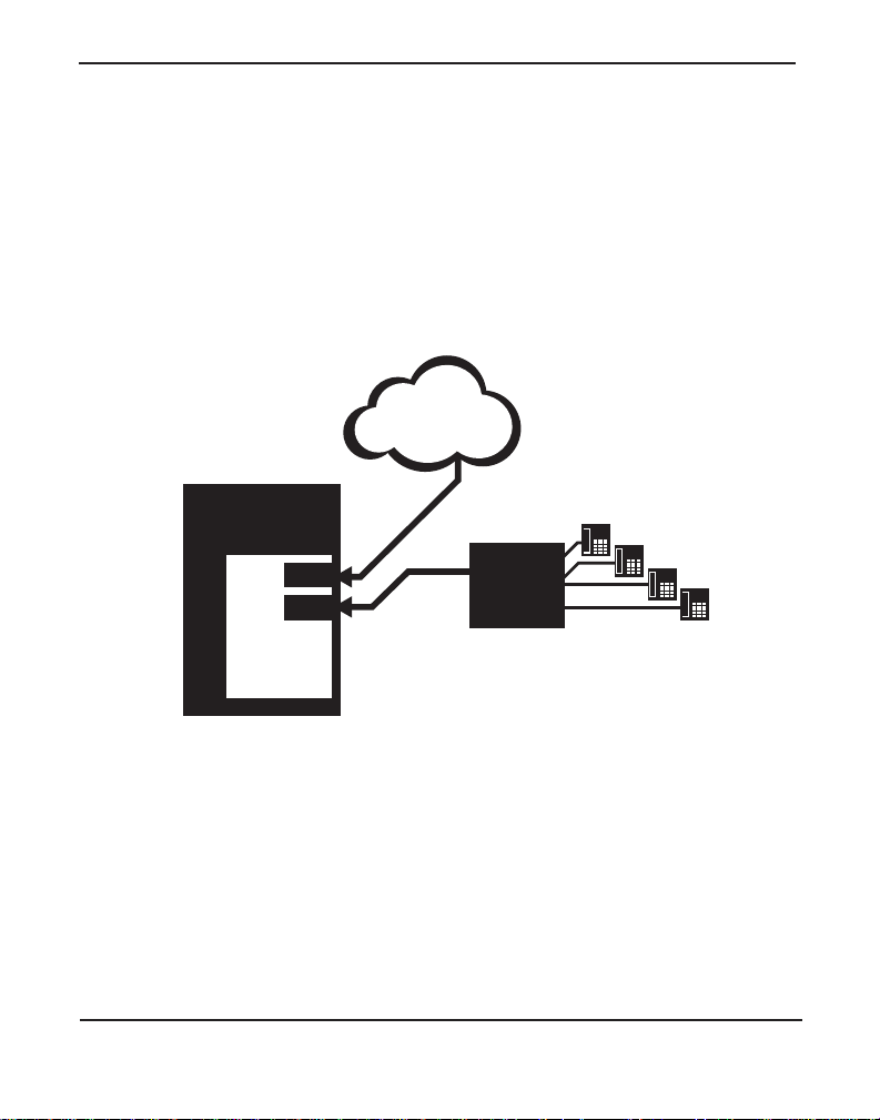
The TE200 Series cards can be used to connect your Asterisk machine to
the PSTN world, your channel bank, or even another PBX. This is
accomplished via a T1/E1 interface. The cards allow Asterisk software to
connect to your network, creating a professional telephony environment.
Figure 2 shows an example of the card’s primary application.
Figure 1: Sample Legacy Phone Application
Digium, Inc. Page 16
Page 17

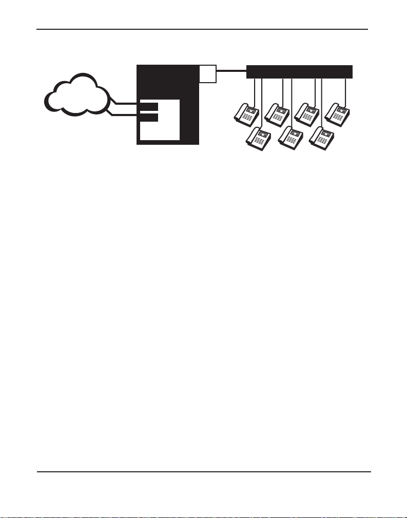
CLEC
Asterisk
Server
TE2xx
Analog
Phones
T1
T1
Channel Bank
Chapter 1: Overview
Figure 2: Sample Channel Bank Application
Digium, Inc. Page 17
Page 18
Chapter 1: Overview
CLEC
ASTERISK
SERVER
TE2xx
Switch
Eth
LAN
IP
Phones
PRI
T1
Figure 3: Sample IP Phone Application
Digium, Inc. Page 18
Page 19

Chapter 1: Overview
Echo-Cancellation
Users connecting their TE200 Series cards to the PSTN or other devices
are likely to be placing calls that will result, at some point, in an
unbalanced 4-wire/2- wire hybrid. The result of this hybrid is the
reflection of a ne ar-end echo to the calling party. Elimination of this echo
is the responsibility of echo canc ellation.
The TE200 Series cards, unless other wise equipped, utilize Asterisk to
perform software-based echo cancellation. Asterisk maintains a number
of open source echo c ancelers. These open source echo cancelers provide
a moderate level of echo cancellation, but are not capable of de aling with
higher levels of, or more advanced, echoes.
Digium recommends that those users concerned about echo cancellation
purchase the VPMOCT64 hardware echo cancellation module. The
VPMOCT64 may be combined with either the TE205P (as TE207P),
TE210P (as TE212P), or TE220 (as TE220B) cards.
The VPMOCT64 is designed to handle up to 128ms of echo cancellation
across all channels and provides a G.168 compliant echo cancellation
solution.
If equipped and not explicitly disabled in chan_dahdi.conf, the
VPMOCT64 will automatically operate and cancel all network echo
within its tail range (1024 ta ps). Users may also purchase Digium's
commercial HPEC software:
http://www.digium.com/en/products/software/hpec.php
Digium, Inc. Page 19
Page 20

Chapter 1: Overview
What is Asteri sk®?
Asterisk is th e world’s le ading open source telephony engine and tool kit.
Offering fle xibility unheard of in the world of proprietary
communications, Asterisk empowers developers and integrators to create
advanced communication solutions...for free. Asterisk is r eleased as open
source under the GNU General Public License (GPL), and it is available
for download free of charge. Asterisk is the most popular open source
software avai lable, with the Asterisk Community being the top influence r
in VoIP.
Asterisk as a Switch (PBX)
Asterisk can be configured as the core of an IP or hybrid PBX, switching
calls, managing routes, enabling features, and connecting callers with the
outside world over IP, analog (POTS), and digital (T1/E1) connections.
Asterisk runs on a wide variety of opera ting systems including Linux,
Mac OS X, OpenBSD, FreeBSD, and Sun Solaris. It provides all of the
features you would exp ect from a PBX inclu ding many adva nced featu res
that are often associate d with high end (and high cost) proprietary PBXs.
Asterisk's archi tecture is designed for maximum flexibility and supports
Voice over IP in many protocols, and can interoperate with almost all
standards-base d telephony equipment using relatively inexpensive
hardware.
Asterisk as a Gateway
It can also be built out as the heart of a media gateway, bridging the
legacy PSTN to the expanding world of IP telephony. Asterisk’s modular
architecture a llows it to co nvert between a wide ran ge of communicat ions
protocols and media codecs.
Digium, Inc. Page 20
Page 21

Chapter 1: Overview
Asterisk as a Feature/Media Server
Need an IVR? Asterisk’s got you covered. How about a conference
bridge? Yep. It’s in ther e. What about an automated attendant? Asterisk
does that too. How about a replacement for your agi ng legacy voicemail
system? Can do. Unified messaging? No problem. Need a telephony
interface for your web site? Ok.
Asterisk in the Call Center
Asterisk has been adopted by call centers around the world based on its
flexibility. Call center and contact center developers have built complete
ACD systems based on Asterisk. Asterisk has also added new life to
existing call center solutions by adding remote IP agent capabilities,
advanced skills-based routing, predictive and bulk dialing, and more.
Asterisk in the Network
Internet Telephony Service Providers (ITSPs), competitive local
exchange carriers (CLECS) and ev en firs t- tier incumbents have
discovered the power of open source communications with Asterisk.
Feature servers, hosted services clusters, voicemail systems, pre-paid
calling solution s, al l based on Asterisk have helped reduce costs and
enabled flexibility.
Aste risk Everywhere
Asterisk has become the basis for thousands of communications
solutions. If you need to communicate, Asterisk is your answer. For more
information on Asterisk visit http://www.asterisk.org
or http://
www.digium.com.
Digium, Inc. Page 21
Page 22

Chapter 2 Card Installation
This chapter provides the following information:
Unpacking the Card on page 23
Shipmen t Ins pec ti o n on page 23
Identifyi ng C om m un ic a tion Por ts on page 24
T1/E1 Selection on page 26
Identifying Multiple Cards on page 26
Connecting Timing Cables on page 27
Slot Compatibility on page 29
Hardware Installat ion on page 31
Software Installation on page 32
Note: The TE200 Series card installation instructions are written so
that they will apply to any card in the series. Examples and card
specific inf ormation are included as need ed.
Digiu m, In c . Pa g e 2 2
Page 23

Chapte r 2: C ar d In st a lla t io n
Unpacking the Card
When you unpack your card, carefully inspect it for any damage that may
have occurred in shipment. If damage is suspected, file a claim with the
carrier and contact your reseller from which the card was purchased, or
contact Digium Technical Support (+1.256.428.6161). Keep the original
shipping container to use for future shipment or proof of damage during
shipment.
Note: Only qualified service personnel should install the card. Users
should not attempt to perform thi s function themselves. The installer
must ensure that the equipment is permanently connected equipment,
pluggable type B or connecte d t o a socke t-outle t tha t has bee n checke d
to ensure that it is reliably earthed in accordance with the National
Electrica l Code.
Shipmen t Ins pec ti o n
The following items are includ ed in shipment of the TE200 Series:
TE200 Series card (TE205P/207P/ 210P/212P/220/220B)
Digium, Inc. Page 23
Page 24

Chapte r 2: C ar d In st a lla t io n
Ports
1
2
Ident
Wheel
PCI 2.2
Connector
Jumpers
Status
LEDs
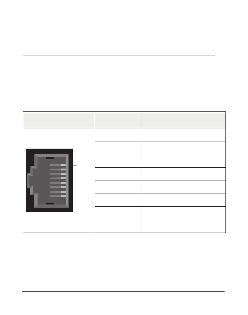
Identifyi ng C om m un ic a tion Por ts
The TE200 Series cards consists of two RJ45 ports and two status LEDs.
The ports are used for connecting T1, E1, or J1 cables. Refer to Figure 4
on page 24 or Figure 5 on page 25 to locate the ports and LEDs.
Figure 4: TE205P Card
Digium, Inc. Page 24
Page 25

Ports
1
2
Status
LEDs
Jumpers
Ident
Wheel
PCI Express
Connector
Timing
Port
Chapte r 2: C ar d In st a lla t io n
Figure 5: TE220 Card
Digium, Inc. Page 25
Page 26

Chapte r 2: C ar d In st a lla t io n
T1/E1 Selection
The card includes a row of jumpers to select either T1 or E1 mode for the
spans. An example of the jumpers from the TE205 card is shown in
Figure 6. The T1/E1 mode, in most cases, is set at the distributor before
shipment. You may want to check the setti ng to be certain they are set for
your specific use. W ith the jumper off, the span is ready for T1 mode, and
with th e jump er on, the span is ready for E1 mode.
Figure 6: T1/E1 Jumpers
Identifying Multiple Cards
If multiple TE200 Series cards are insta lled in the same machine, then the
Ident wheel can be used to control the or der the ca rds are recognize d. The
click wheel switch with the word Ident printed above it can be set to a
different num ber for each installed card. This num ber adjusts the order in
which the drive r recognizes the card. F or example: set the fi rst card Ident
wheel to 0, set the sec ond card Ident wheel to 1, and so on. The Ident
wheel is shown in Figure 7.
Digium, Inc. Page 26
Page 27

Chapte r 2: C ar d In st a lla t io n
Figure 7: Ident Wheel
Connecting Timing Cables
The timing por t allow s up to four TE 2 00 Se rie s card s to share the sa me
sync (timing) source from the T1 line provider, or provide a consistent
sync source across multipl e cards. This is a useful fea ture for data and fax
modes and some voice applications to prevent corruption due to timing
slips on the second, third or fourth TE200 Series cards.
T o utilize this feature, daisy-chain the P1 connector between each TE200
Series card using the Digium 4-posi tion timing cable. See Figure 8 on
page 28 for an example. Enable this featur e in the drivers using the
timingcable=1 switch when the drivers are loaded:
# modprobe wct2xxp timingcable=1
Digium, Inc. Page 27
Page 28
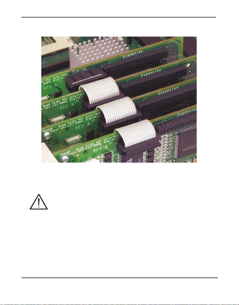
Chapte r 2: C ar d In st a lla t io n
Figure 8: Timing Ports Example
Caution.
Only qualified service personnel should continue with
hardware installation and configur ation of the TE200 Series
card. Non-qualified personnel should not attempt to perform
these functions themselves.
Digium, Inc. Page 28
Page 29

Chapte r 2: C ar d In st a lla t io n
0
1
2
3
4
Slots
Slot Compatibility
Check the type of card you received to be sure it is compatible with your
PCI slot. To determine which slot you have, identify it by comparing it to
those shown in Figure 9 on page 29.
Slot Number:
0: AGP Pro Slot
1: 64-bit 5.0 volt PCI Slot
2: 64-bit 3.3 volt PCI Slot
3: 32-bit 5.0 volt PCI Slot
4: PCI Express X1 Slot
Figure 9: Motherboard PCI Slots
Digium, Inc. Page 29
Page 30

Chapte r 2: C ar d In st a lla t io n
The TE205P/207P card is a 32-bit 33MHz card keyed for 5.0 volt
operation and works in any PCI 2.2 (or higher) compliant slot which
supports 5.0 volts. This means that in the motherboard shown in Fi gure 9,
the TE205P/207P card will fit into Slots 1 and 3. The TE205P/207P will
not fit into Slot 0 (AGP slot) or Slot 2.
The TE210P/212P card is a 32-bit 33MHz card keyed for 3.3 volt
operation and works in any PCI 2.2 (or higher) compliant slot which
supports 3.3 volts. This means that in the motherboard shown in Fi gure 9,
the TE210P/212P card will only fit into Sl ot 2. The TE210P/212P will
not fit into Slots 1 or 3.
The TE220/TE220B card is a PCI Express card. Slot 4, ill ustrated above,
is a 1 lane (X1) PCI Express compliant slot. The TE220/TE220B will
work in any PCI Express compliant slot, including lane lengths X4, X8,
and X16. This means that in the motherboard shown in Figure 9, the
TE220/TE220B will only fit into Slot 4. The TE220/TE220B can not be
used in Slots 1 through 3.
Digium, Inc. Page 30
Page 31

Chapte r 2: C ar d In st a lla t io n
Hardware Installat ion
1. Now that you are acquainted with the cards , power down your
computer and unplug it from its power sourc e.
2. Attach a static strap to your wrist a nd open the case .
3. Check the jumper setting to ensure it matches your equipment
configuration. Setting the jumper with the jumper strap on enables the
ports for E1. Setting the jumper with the jumper strap off enabl es the
ports for T1.
4. Remove the bracket place holder and insert the card into a PCI or PCI
Express slot. See Figure 10 for an example of card installation.
Figure 10: Insert the Card
5. Replace the cover to your computer.
6. Plug all T1 or E1 equipment cables into the RJ45 ports as needed.
Note: It is recommended that you use shielded cables.
Digium, Inc. Page 31
Page 32

Chapte r 2: C ar d In st a lla t io n
Caution.
This unit must be connected to the Telecommunications
Network in your country using an approve d line cord (e.g. for
Australia use only line cords complying with ACA Technical
Standard TS008).
Caution.
This unit must be connected only to the appropriate
Telecommunications Network port (as approved for use in your
specific country).
Software Installation
Digium hardware requires driver s and libraries that are not integrated
with the Linux kernel. Digium hardware is only supported under Linux.
Digium recommends CentOS, Debian, R ed Hat, and Ubuntu distribut ions
of Linux. However, many other distributions are supported by Digium
Technical Support.
Digium’s software, including drivers and application software, may be
obtained from Digium’s download server at:
http://downloads.digium.com
For an introduction to Asterisk, Digium’s telephony software, including
additional infor mation on its configuration, setup, and features, please
refer to:
http://www.asterisk.org
For the latest information on se tting up and configuring DAHDI drivers
for your Digium hardwar e product, please refer to t he lat est relea se of t his
manual which is available fro m the product-specific documentation
section at:
http://www.digium.com
Digium, Inc. Page 32
Page 33

Chapte r 2: C ar d In st a lla t io n
To install your TE200 Series card, you will need:
Linux 2.6 kernel headers
Development librarie s and head ers for ncurses
Development librarie s and head ers for zlib and openssl
Development librarie s and headers for newt
GCC and standard software build tool s
It is recommended that you use the most recent version of the Asterisk,
DAHDI, and libpri software for the best results. If you have previously
installed any of these, Digium recommends that you upgrade to the latest
“-current” version of each.
Note: If you are using the 1.4.x series of Asterisk, you will need
Asterisk 1.4.22 or newer.
Digium, Inc. Page 33
Page 34

Chapte r 2: C ar d In st a lla t io n
1. After the machine has booted to Linux, log in and execute the
following command to list the devic es detected by the PCI bus:
# lspci -n
Confirm that the output from lspci lists a device with Digium’s PCI
vendor ID which is “d161”. The screen output should be simila r to the
following:
0000:01:0e.0 ISDN controller: Unknown device
d161:<card identifier>
Note: The output from lspci may or may not state “Unknown
device”. If it does, this does not indicate a problem.
In the PCI device listing shown above, <card identifier> will be
populated with one of the identifiers listed in the table below.
Digium, Inc. Page 34
Page 35

Chapte r 2: C ar d In st a lla t io n
Table 1: Card Identifiers
Model Identifier
TE220B
TE220
TE212P
TE210P
TE207P
TE205P
0220
0220
0210
0210
0205
0205
A Digium TE200 Series (TE220B/TE220/212P/210P/207P/205P)
card identifier should be listed. If a matching card identifier is not
listed, then your machine is not PCI 2.2 (or higher) or PCI Express
compatible, and the card will not work with your motherboard.
2. Download the latest versio n of libpri. Substitute the version of libpri
for the X.X in the command line below. libpri is available for
download from:
http://downloads.digium.com/pub/telephony/libpri
# wget http://downloads.digium.com/pub/telephony/
libpri/libpri-X.X.current.tar.gz
.
Note: There is no coorelation between the versioning of libpri and
Asterisk. The libpri 1.4 br anch will function with the Asterisk 1.6
branch.
Digium, Inc. Page 35
Page 36

Chapte r 2: C ar d In st a lla t io n
3. Expand the dow nl oad ed file , compile its contents , and insta l l the
libraries. Substitute the version of libpri for the X.X and X.X.X in the
command lines below.
# tar -zxvf libpri-X.X-current.tar.gz
# cd libpri-X.X.X/
# make
# make install
Download the latest DAHDI drivers with tools. DAHDI is available
4.
for download from:
http://downloads.digium.com/pub/telephony/dahdi-linux-complete
# wget http://downloads.digium.com/pub/telephony/
dahdi-linux-complete/dahdi-linux-completecurrent.tar.gz
5.
Expand the dow nl oad ed file , compile its contents , and insta l l the
drivers and tools. Substitute the version of DAHDI for the X.X.X in
the command lines below.
# tar -zxvf dahdi-linux-complete-current.tar.gz
# cd dahdi-linux-complete-X.X.X+X.X.X
# make
# make install
# make config
Note: Executing ‘make config’ will install an init script and symlinks
which will allow you to start and stop DAHDI as a service.
Digium, Inc. Page 36
Page 37

Chapte r 2: C ar d In st a lla t io n
Installing Asteris k
If you wish to use Asterisk with your new hardware, you can follow the
instructions below.
1. Download the latest relea se version of Aste risk, either 1.4.22 ( or later)
or 1.6.0.1 (or later). Substitute the version of Asterisk for the X.X in
the command below. Asterisk is available for download from:
http://downloads.digium.com/pub/telephony/asterisk
# wget http://downloads.digium.com/pub/telephony/
asterisk/asterisk-X.X-current.tar.gz
Expand the dow nl oad ed file , compile its contents , and insta l l the
2.
application. Substitute the version of Asterisk for the the X.X and
X.X.X in the command lines below.
# tar -zxvf asterisk-X.X-current.tar.gz
# cd asterisk-X.X.X/
# ./configure
# make menuselect
# make
# make install
Digium, Inc. Page 37
Page 38

Chapte r 2: C ar d In st a lla t io n
3. If this i s the fir st Aste risk i nstall at ion on th is s ystem, you sho uld install
the sample configurati on files. To do this, run:
# make samples
Note: Running this command will overwrite, after making a backup
copy, any older Asterisk configura tion files that you have in the /etc/
asterisk directory.
If your installation has failed, it may be because you are missing one
or more of the build dependencies, the kerne l headers, or the
development tools. Please contact your reseller where the card was
purchased, or call Digium Technical Support (+1.256.428.6161) for
assistance.
Complete instructi ons for installing Asterisk are available at
www.asterisk.org
.
Digium, Inc. Page 38
Page 39

Chapter 3 Configuration
The TE200 Series cards have a variety of configuration options. This
chapter provides confi gurations for PRI, channel bank, E&M wink, and
finally, data mode. These sample conf igura tions a re provi ded to a ssist y ou
in familiarizing yourself with the flexibility of editing the configuration
files to meet your specific needs. The list of possibl e configur ations is too
expansive to cover in this user manual.
Digiu m, In c . Pa g e 3 9
Page 40

Chapter 3: Configuration
Configuring Card Feature s
You will need to modify the chan_dahdi.conf file which is loca ted in the
/etc/asterisk directory in order to configure the essential features of your
card. This file is the configuration layer between DAHDI and Asterisk.
Switchtype:
national: National ISDN 2 (default)
dms100: Nortel DMS100
4ess: AT&T 4ESS
5ess: Lucent 5ESS
euroisdn: EuroISDN
ni1: Old National ISDN 1
qsig: Q.SIG
Echocancel:
Echo Cancellation is enabl ed in chan_dahdi.conf by preceding the
channel variab le with a variable ca lled ech ocancel a nd it s lengt h in t aps (#
of milliseconds multiplied by 8); for example:
echocancel = yes
channel => 1-23
By default, and when set ting to " yes," echo ca ncellat ion i s enabled and set
to 16 ms (128 taps). Echo cancellation is expl icitly disabled by setting:
echocancel = no
Digium does not recommend that users set echo cancellation to "no."
Users of open source Asterisk-based echo cancelers also have the
following options:
echocancel = 128 (this sets 128 taps or 16ms)
Digium, Inc. Page 40
Page 41

Chapter 3: Configuration
or
echocancel = 256 (this sets 256 taps or 32ms)
Users of Digium's HPEC software have the following additional options:
echocancel = 512 (this sets 512 taps or 64ms)
or
echocancel = 1024 (this sets 1024 taps or 128ms)
Please note that HPEC consumes extremel y high amounts of CPU MIPS
that increase as the number of taps are increased. Audio quality issues
may result from choosing a taps length greater than the server's ability to
process the echo in real-time. If audio quality is affected, reduce the taps
length or combine your TE200 Series card with Digium 's VPMOCT64.
Users of Digium's VPMOCT64 hardware echo cancellation module will
have 128ms of echo cancellation performed at all times unless explicitly
disabled by setting the echocancel variable equal to "no."
Digium, Inc. Page 41
Page 42

Chapter 3: Configuration
Signalling:
pri_cpe for CPE side
pri_net for NET side
If you have a T1 PRI, add these lines to the following lines of the sample
file.
signalling = pri_cpe
switchtype = national
group = 1
context = incoming
channel => 1-23
E1 PRI
signalling = pri_cpe
switchtype = euroisdn
context = incoming
channel => 1-15,17-31
You can also configure a T1 channel bank of phones
signalling = fxo_ks
group = 1
context = phones
channel => 1-24
E1 channel bank
signalling = fxo_ks
group = 1
context = phones
channel => 1-15,17-31
Note: More detailed troubleshooting information is provided on http://
www.asterisk.org.
Digium, Inc. Page 42
Page 43

Chapter 3: Configuration
Configuring T1/E1 Lines
1. Begin by opening the system.conf file from the /etc/dahdi directory.
2. Specify the two lett er country c ode for your loa dzone and defaultz one.
This will preload tone zone data and specif y a def ault tone zone for
your interfaces.
The following is a typical setup for a telco in the US:
loadzone = us
defaultzone = us
Configure the SPAN Map.
3.
For each T1/E1 you are using, you will need to define a span. The
SPAN map includes defining the SPAN number, timing, line bu ild out ,
framing, and coding. Configur ation details for each of these items is
explained in this section.
span => <Number>,<Timing>,<Line Build
Out>,<Framing>,<Coding>[,Yellow]
Number:
This is the port the T1/E1 l ine is plugg ed i nto. Port 1 be ing the fur thest
span from the PCI bus. The port numbers are noted on the PCI bracket .
Digium, Inc. Page 43
Page 44

Chapter 3: Configuration
Timing:
This determines how timing is handle d by the card.
0 - Card provides its own timing
1 - Receives tim ing fro m remo t e end
2 - Receives secondary backup timing from remote end
3 - Receives tertiary backup timing from remote end
4 - Receives quaternary backup timing from remote end
Only one span can be defined to take timing, and it define s timing for
the rest of the card ’s spans.
Line Build Out:
For most setups the line build out is 0.
0: 0 db (CSU) / 0-133 feet (DSX-1)
1: 133-266 feet (DSX-1)
2: 266-399 feet (DSX-1)
3: 399-533 feet (DSX-1)
4: 533-655 feet (DSX-1)
5: -7.5db (CSU)
6: -15db (CSU)
7: -22.5db (CSU)
Framing:
T1 utilizes framing set for D4 (SF) or ESF. E1 utilizes CAS or CCS.
Digium, Inc. Page 44
Page 45

Chapter 3: Configuration
Coding:
T1 coding can be AMI or B8ZS. E1 coding can be AMI or HDB3. E1
can also have the extra flag CRC4 at the end for CRC4 checking.
Yellow:
The optional yellow flag can be added at the end for transmitting a
yellow alarm when no channels are open.
The following is a typical setup for a telco in the US:
span => 1,1,0,esf,b8zs
In Europe:
span => 1,1,0,ccs,hdb3
Specify the channel defin itions. The format is:
4.
<device> = <channel list>
A list of valid devices are specified in the sample system.conf file.
The followi ng is a typica l set up for a T1 PRI in the US:
bchan = 1-23
dchan = 24
DAHDI uses modular echo cancellers that are configured per channel.
5.
The echo cancellers are compiled and installed as part of the dahdilinux package. You can specify the echo canceller to be used for each
channel. The default behavior is for there to be no echo canceller on
Digium, Inc. Page 45
Page 46

Chapter 3: Configuration
any channel. So, it is very important that you specify one in the
system.conf file if you do not have ha rdware echo cancellers and need
echo cancel latio n . Th e format is:
echocanceller = <echocanceller name>,<channel(s)>
A list of valid echo cancellers are specified in the sample system.conf
file.
The following i s a typical setup for a T1 PRI in the US usin g softwarebased echo cancellation:
echocanceller = mg2,1-23
Digium, Inc. Page 46
Page 47

Chapter 3: Configuration
First Example: Channel Bank
The Channel Bank in this example has 24 FXS ports. In this
configuration, the system.conf is set for the card to provide timing to the
channel bank and fxoks is set for 24 stations.
chan_dahdi.conf to mirror the configuration with signalling =
Set
fxo_ks
and define it for channels 1-24.
/etc/dahdi/system.conf:
loadzone = us
defaultzone = us
span = 1,0,0,esf,b8zs
fxoks = 1-24
echocanceller = mg2,1-24
/etc/asterisk/chan_dahdi.conf:
group = 1
echocancel = yes
context = channelbank
signalling = fxo_ks
channel = 1-24
Digium, Inc. Page 47
Page 48

Chapter 3: Configuration
Second Example: E&M Line
In the E&M Line configuration, the system.conf is set for the card to
take timing from the telco on E&M with wink while chan_dahdi.conf
mirrors the configuration. Feat_D is a type of E&M with wink that
accepts DID, but there are many E&M options; E&M_W, E&M, Feat_B,
etc.
/etc/dahdi/system.conf:
loadzone = us
defaultzone = us
span = 1,1,0,esf,b8zs
e&m = 1-24
echocanceller = mg2,1-24
/etc/asterisk/chan_dahdi.conf:
group = 1
echocancel = yes
context = incoming
signalling = feat_d
channel = 1-24
Digium, Inc. Page 48
Page 49

Chapter 3: Configuration
Third Example: PRI
By configuring the card for a T1 PRI line in system.conf, you acquir e 23
bearer (B) channels for voice on the first 23 channels, and 1 delta (D)
channel for signalling information on the 24th channel. In the
chan_dahdi.conf file, define pri_cpe as the signalling type to act as the
client side. Define the switch t ype you are connecting to as national. You
will then have 23 voice channels for Asterisk.
PRI T1:
/etc/dahdi/system.conf:
loadzone = us
defaultzone = us
span = 1,1,0,esf,b8zs
bchan = 1-23
dchan = 24
echocanceller = mg2,1-23
/etc/asterisk/chan_dahdi.conf:
group = 1
echocancel = yes
signalling = pri_cpe
switchtype = national
context = incoming
channel = 1-23
Digium, Inc. Page 49
Page 50

PRI E1:
/etc/dahdi/system.conf:
loadzone = es
defaultzone = es
span = 1,1,0,ccs,hdb
bchan = 1-15,17-31
dchan = 16
echocanceller = mg2,1-15,17-31
/etc/asterisk/chan_dahdi.conf:
group = 1
echocancel = yes
signalling = pri_cpe
switchtype = euroisdn
context = incoming
channel = 1-15,17-31
Chapter 3: Configuration
Digium, Inc. Page 50
Page 51

Chapter 3: Configuration
Fourth Example: Data Mode
Data mode is a little different than the other options. The system.conf is
configured as follows:
loadzone = us
defaultzone = us
span = 1,0,0,esf,b8zs
nethdlc = 1-24
Instructions for Cisco HDLC:
1. Compile the Linux kernel with Cisco HDLC support. The Linux
kernel menuconfig menu may look similar to the following:
Device Drivers --->
[*] Network device support --->
[*] Wan interfaces support --->
<M> Generic HDLC support
<M> Cisco HDLC support
Note: Digium recommends using Linux kernel version 2.6.8 or later.
The HDLC implementation in Linux kernel vers ions prior to 2.6.8
may not be reliable or function at all.
2. Install the newly compiled Linux ke rnel.
Digium, Inc. Page 51
Page 52

Chapter 3: Configuration
3. Reboot into the new Linux kernel.
4. Uncomment the foll owing line in linux/drivers/dahdi/
dahdi_config.h
#define CONFIG_DAHDI_NET
Rebuild DAHDI in order to compile the sethdlc utility. Then execute
5.
of the DAHDI complete source package:
the following commands from the DAHDI complete sour ce dir ectory:
# make sethdlc
# make install
Load and configure the driver:
6.
# modprobe wct4xxp
# dahdi_cfg
Use sethdlc to bring up the interface:
7.
# sethdlc hdlc0 cisco
8.
Assign the interface an address:
# ifconfig hdlc0 192.168.0.1 netmask 255.255.255.0
The interface may be addressed as any other networking interface
9.
(i.e., eth0) in Linux.
Digium, Inc. Page 52
Page 53

Chapter 3: Configuration
Testing Your Co nfigur ation
1. Load DAHDI drivers into the kernel using the modprobe utility. The
appropriate driver for the TE200 Series cards is wct4xxp. Users in all
countries except Austra lia should use the following modprobe
command:
# modprobe wct4xxp
# dahdi_cfg -vv
# dmesg
Digium, Inc. Page 53
Page 54

Chapter 3: Configuration
Figure 11: Example dmesg Output
Note: Output as shown above may vary depending on the TE200
Series card you use.
2. Run dahdi_tool from the command line and see if the span turns
green for each span you have connected.
# dahdi_tool
Digium, Inc. Page 54
Page 55

Chapter 3: Configuration
3. Execute the follo w ing A ste ri sk command to see if the span came up
successfully.
# asterisk
# asterisk -vvvr
Digium, Inc. Page 55
Page 56

Chapter 4 Troubleshooting
This chapter provides frequently asked questions as identified from
Digium Technical Support and possible resolutions. Multiple resource s
are available to obtain more infor mation about Asterisk and Digium
products. These resources are listed on page 62.
What do the Status LED co lo rs indi cate?
Green - Card is in-sync with the far end.
Yellow - Card is synchronizing or is re ceiving a red alar m from the far
end. Use a software tool such as dahdi_to ol to get a textua l descri ption
of the state o f the card.
Red - Card is not seeing far end, circuit is not up, or cable is bad.
I can't receive DID calls even though I have it enabled in
extensions.conf.
Your telco might be sending calls with a method you are not expecting.
1. Check the method being used by attempting the following in your line
context:
_X.,1,NoOp(My DID matches as ${EXTEN})
Digiu m, In c . Pa g e 5 6
Page 57

Chapter 4: Troubleshooting
2. Then type reload in the Asterisk console and call in. You should see
the DID come in on your T1/E1 line.
My D Channel seems to go up and down.
Check to be sure you have set your timing parameters correctly. Also,
check the common causes of problems for a T1. See the Common Fixes
for all cards , page 60.
I have trouble dialing out. It seems that one type of dialing works
(local, long distance, in ternational), but another does not.
Check your
pridialplan variable and verify that you are dialing using the
method your telco is expecting .
I am having trouble receiving DID information over E&M.
Try the other types of E&M (featd, featb, etc.) to match the method your
telco is using to stream infor mation.
I am having issues with my PRI. How can I see the messages coming
across my D chan nel?
Enter the following command:
*CLI> PRI debug span X
where X is the port from which you are connected. This command will
show you the PRI messages coming across your D channel for that span.
Digium, Inc. Page 57
Page 58

Chapter 4: Troubleshooting
I am still having problems and the telco tells me it is my equipment.
The first thing to do in this situat ion is to test your equipment.
1. Plug in a loopback cable. (A loopback cable is a cable that has pin 1
going to pin 4 and pin 2 going to pin 5.) Plug the cable into the span
and wait for its LED to turn green.
2. Stop Asterisk a nd edit system.conf by removing the lines defined for
your card and replacing them with the following:
span => 1,0,0,esf,b8zs
clear = 1-24
Or if you have an E1 span:
span => 1,0,0,ccs,hdb3
clear = 1-31
Digium, Inc. Page 58
Page 59

Chapter 4: Troubleshooting
3. Navigate to the tools/ dire ctory in your DAHDI complete source
directory and type:
# make tests
Followed by:
# ./patlooptest /dev/dahdi/1 60
The first argument in the patlooptest command is the device for the
channel number you want to test. You should always test the first
channel of a span. The second argumen t i s the duration in seconds to
run the test.
This runs a pattern looptest for 60 seconds. If you receive any failures,
it is possible you have a bad card and will need to call Digium
Technical Support (+1.256.428.6161)
How can I enable more features?
To view all of the options available to add to your dial plan, type the
following commands from within Aster isk:
*CLI> core show applications
*CLI> core show functions
Digium also offers services to help configure and add features you might
need. Contact Digium Technical Support (+1.256.428.6161) for more
information.
Digium, Inc. Page 59
Page 60

Chapter 4: Troubleshooting
Common F ixe s for all cards
1. Check to see if the X W indow Sy stem (e.g. X.Org Server) is running
by entering the following:
# ps aux | grep X
If the X Window System is running, stop the application since it may
cause a conflict with Asterisk.
2. Check to see if your PATA I DE hard drives are running with DMA
levels set. Advance user can perform an
hdparm on your hard drive
interface.
Use hdparm with caut ion as t he man pa ge st ates that h ar d drive
corruptio n can occur when using incorrect settings. Pl ease
review t he man page for hdp arm and mak e sur e you unde rst and
the risks before using this tool.
Check the current mode using this command:
hdparm -vi /dev/[IDE Device]
Use this command to set the drives into UDMA2 mode:
hdparm -d 1 -X udma2 -c 3 /dev/[IDE Device]
If you are still having problems, contact your reseller from which the
card was purchased, or Digium Technical Support (+1.256.428.6161).
Digium, Inc. Page 60
Page 61

Chapter 4: Troubleshooting
Where can I find answers to additional questions?
There are several places to inquire for more information about Asterisk
Digium products:
1. Digium Technical Support (+1.256.428.6161) , or Toll Free in the U.S.
(1.877.344.4861), is available 7am-8pm Central Time (GMT -6),
Monday - Friday.
2. Asterisk users mailing list (asterisk.org/lists.digium.com).
3. IRC channel #asterisk on (irc.freenode.net).
Subscription Services Program
Digium is dedicated to support ing your Asterisk system by offering full
technical support through our Subscription Services Program. Through
this program, you can be at ease knowing that your business will always
have access to the Asterisk expert s. Prici ng on Subscription Servic es may
be obtained from your nearest reseller or you may call Digium Sales for
referral to your neares t rese ller at +1.256.428.6000 or e-mail
sales@digium.com.
Digium, Inc. Page 61
Page 62
Appendix A
Pin 8
Pin 1
Pin Assignments
Both ports on the TE20 0 Serie s card br acket are 8-pin R J45 p orts. The pin
assignments are identif ied in Tab le A-1.
Tab le A-1: RJ45 Telco Port Connec t or
Pin Description
1Rx
2Rx
3Not used
4Tx
5Tx
6Not used
7Not used
8Not used
Digiu m, In c . Pa g e 6 2
Page 63

Appendix B Specifications
This appendix provides specifications, required environmental
conditions, and maximum power consumption f or the T E200 Series
cards.
Physical (All Cards).
Size: 5” × 3.75” × 0.63” (12.7 x 9.53 x 1.6 cm)
PCB size, does not include the PCI bracket
Weight: 3.5 oz (100gm) - Without Echo Cancellation Module
Interfaces.
Local Loop Access: E1, T1, J1, PRI; RJ45
(TE205P/207P/210P/212P) - PCI Bus: 3.3V or 5V bus slot, halflength slot minimum size, 33MHz minimum bus speed, compliant
with PCI 2.2 or greater.
(TE220) - PCI-E X1, compliant with PCI-E X1 1.0 or greater.
Environment.
Temperature: 0 to 50° C (32 to 122° F) operation
-20 to 65° C (4 to 149° F) storage
Humidity: 10 to 90% non-condensing
Digiu m, In c . Pa g e 6 3
Page 64

Appendix B: Specifications
Hardware an d Softw a re Requirements.
800-Mhz Pentium III or better
64MB RAM
Available PCI (TE205P/207P/210P/212P) or PCI-E (TE220) Slot
Table B-2: Maximum Power Consumption
Model Power
TE220B
3.3V 4.0 Watts
TE220
3.3V 2.0 Watts
TE212P
3.3V
5V
TE210P
3.3V
5V
2.5 Watts
0.5 Watts
1.5 Watts
0 W atts
TE207P
3.3V
5V
2.5 Watts
0.5 Watts
TE205P
3.3V
5V
Digium, Inc. Page 64
1.5 Watts
0 W atts
Page 65

Appendix C Gloss ary and Acronyms
ANSI American National Standards Institute
An organization which proposes and establishes standards for
international communications.
asynchronous
Not synchronized; not timed to an outside clock source. Transmission is
controlled by start bits a t the beginning and stop bits at the end of each
character. Asynchronous communications are often found in internet
access and remote office applications.
attenuation
The dissipation of a transmitted signal’s power as it travels over a wire.
bandwidth
The capacity to carry traffic. Higher bandwidth indicates the ability to
transfer more data in a given time period.
bit
The smallest element of information in a digital system. A bit can be
either a zero or a one.
bps bits per second
A measurement of transmission spe ed across a data connection.
Digiu m, In c . Page 65
Page 66

Appendix C Glossary and Acronyms
broadband
Broadband transmission sha res the bandwidth of a particular medium
(copper or fiber optic) to integrate multiple signals. The channels take up
different f requencies on the cable, integrating voic e, data, and video over
one line.
channel
A generic term for an individual dat a stre am. Ser vice providers can use
multiplexing techniques to transmit multiple channels over a common
medium.
Cat5
Category of Performance for wiring and cabling. Cat 5 cabling support
applications up to 100 MHz.
Cat5E
Category of Performance for wiring and cabling. Category 5 Enhanced
wiring supports signal r ates up to 100 MHz but adheres to stricter quality
specifications.
CLEC competitive local exchange carrier
A term for telephone companies established after the
T elecommunications Act of 1996 deregulated the LECs. CLECs compete
with ILECs to offer local service. See als o LEC and ILEC.
Digium, Inc. Page 66
Page 67

Appendix C Glossary and Acronyms
CO central office
The CO houses local switching equipment. All local access lines in a
particular geographic area terminate at this facility (which is usually
owned and operated by an ILEC).
CPE customer premises equipment
T erminal equipment which is connected to the telecommunications
network and which resides within the home or of fice of the customer . This
includes telephones, modems, terminals, routers, and television set-top
boxes.
DAHDI Digium Asterisk Hardware Device Interface
A telephony project dedicated to implementing a reasonable and
affordable compute r tele phony plat form in to t he wor ld mar ketpla ce. Al so,
the collective name for the Digium -provided drivers for Digium
telephony interface products.
DS0 Digital Signal, Level 0
A voice grade channel of 64 Kbps. The worldwide standar d speed for
digitizing voice conversation using PCM (Pulse Code Modulation).
DS1 Digital Signal, Level 1
1.544 Mbps in North America (T1) and Japan (J1) -up to 24 voice
channels (DS0s), 2.048 Mbps in Europe (E1) - up to 32 voice channels
(DS0s). DS1/T1/E1 lines are part of the PSTN.
Digium, Inc. Page 67
Page 68

Appendix C Glossary and Acronyms
DS3 Digital Signal, Level 3
T3 in North America and Japan, E3 in Europe. Up to 672 voice channels
(DS0s). DS3/T3/E3 lines are not part of the PSTN
DTMF Dual Tone Multi-Frequency
Push-button or touch tone dial ing.
E1
The European equivalent of North Ameri can T1, transmits data at 2.048
Mbps, up to 32 voice channels (DS0s).
E3
The European equival ent of North American T3, transmits data at 34.368
Mbps, up to 512 voice channels (DS0s). Equivale nt to 16 E1 lines.
EMI Electromagnetic Interference
Unwanted electrical noise present on a power line
full duplex
Data transmission in two directions simultaneously.
FXO Foreign Exchange Office
Receives the ringing volta ge from an FXS device.
FXS Foreign Exchange Station
Initiates and sends ringing voltage.
Digium, Inc. Page 68
Page 69

Appendix C Glossary and Acronyms
G.711
A recommendation by the Telecommunication Standardization Sector
(ITU-T) for an algorithm designe d to transmit and receive mulaw PCM
voice and A-law at a digita l bit rate of 64 Kbps. This algor ithm is used fo r
digital telephone sets on digital PBX.
G.72 3.1
A recommendation by the Telecommunication Standardization Sector
(ITU-T) for an algorithm designe d to transmit and receive audio over
telephone lines at 6.3 Kbps or 5.3 Kbps.
G.72 9a
A recommendation by the Telecommunication Standardization Sector
(ITU-T) for an algorithm designe d to transmit and receive audio over
telephone lines at 8 Kbps.
H.323
A recommendation by the Telecommunication Standardization Sector
(ITU-T) for multimedia communic ations over packet-based networks.
IAX Inter-Asterisk eXchange
The native VoIP protocol used by Asterisk. It is an IETF standard used to
enable VoIP connections between Asterisk servers, and between servers
and clients that also use the IAX protoc ol.
Digium, Inc. Page 69
Page 70

Appendix C Glossary and Acronyms
iLBC internet Low Bitrate Codec
A free speech codec used for voice over IP. It is designed for narrow band
speech with a payload bitrate of 13.33 kbps (frame length = 30ms) and
15.2 kbps (frame length = 20 ms).
ILEC incumbent local exchange c arrier
The LECs that were the or iginal carr iers in the market pr ior to th e entry of
competition and theref ore have the dominant position in the market.
interface
A point of contact between two systems, networks, or devices.
ISO International Standards Organization
LED light-emitting diode
Linux
A robust, feature-packed open source operating system based on Unix
that remains freely available on the internet. It boasts dependability and
offers a wide range of compatibility with hardware and software. Asterisk
is supported exclusively on Linux.
loopback
A state in which the transmit signal is reversed back as the receiv e signal,
typically by a far end network element.
Digium, Inc. Page 70
Page 71

Appendix C Glossary and Acronyms
MGCP Media Gateway Control Protocol
multiplexing
Transmitting multiple signals over a single line or chan nel. FDM
(frequency divisi on multiplexing) and TDM (time division multiplexing)
are the two most common methods. FDM separates signals by dividing
the data onto different carrier frequencies, and TDM separates signals by
interleaving bit s one after the other.
MUX multiplexer
A device which transmits multipl e signals over a single communications
line or channel. See multiplexing.
PBX private branch exchange
A smaller version of a phone company’s large central switching office.
Example: Asterisk.
PCI periph eral compo nent interconnect
A standard bus used in most computers to connect peripheral devices.
POP point of presence
The physical connection point between a network and a telephone
network. A POP is usually a network node serving as the equivalent of a
CO to a network service provider or an interexchange carrier.
POTS plain old telephone service
Standard phone service over the public switched telephone network
(PSTN). This service provides analog bandwidth of less than 4 kHz.
Digium, Inc. Page 71
Page 72

Appendix C Glossary and Acronyms
PPP point-to-point protocol
Type of communications link that connects a single device to another
single device, such as a remote terminal to a host computer.
PSTN public switched telephone network
The public switched teleph one network (PSTN) is the network of the
world's public circuit-switched telephone networks. Originally a network
of fixed-line analog te lephone systems, the PSTN is now almost entirely
digital, and now includes mobile as well as fixed telephones.
QoS quality of service
A measure of telephone service, as specified by the Public Service
Commission.
RJ11
A six-pin ja ck typically used for connecting telephones, modems, and fax
machines in residentia l and business settings to PBX or the local
telephone CO.
SIP Session Initiation Protocol
An IETF standard for setting up sessions be tween one or more clients. It
is currently the leading signaling protocol for Voice over IP, gradually
replacing H.323.
T1
A dedicated digital carrier facility which transmits up to 24 voice
channels (DS0s) and transmit s data at 1.544 Mbps. Commonly used to
carry traff ic to and from private business networks and ISPs.
Digium, Inc. Page 72
Page 73

Appendix C Glossary and Acronyms
T3
A dedicated digital carrie r facility which consists of 28 T1 lines and
transmits data at 44.736 Mbps. Equivalent to 672 voice channels (DS0s).
TDM time division multiplexer
A device that supports simul taneous transmissi on of multiple data streams
into a single high-speed dat a stre am. TDM separa tes signals by
interleaving bit s one after the other.
telco
A generic name which refers to the telephone companies throughout the
world, including RBOCs, LECs, and PTTs.
tip and ring
The standard terminati on on the two conduct ors of a telephone circuit;
named after the physical appear a nce of the contact areas on the jack plug.
twisted pair
T wo copper wires commonly used for telephony and data
communications. The wires are wrapped loosely around each other to
minimize radio frequency interference or interference from other pairs in
the same bundle.
V volts
VoIP Voice over IP
T echnology used for transmitti ng voice tr affic over a data network using
the Internet Protoco l.
Digium, Inc. Page 73
 Loading...