

Page 1

800 Series
AEX800/TDM800P
User Manual
601-00008A Rev. C
Page 2

445 Jan Davis Drive
Digium, Inc.
Huntsvil le, AL 35806
United States
Main Number: 1.256. 428.6000
Tech Support : 1.2 56.428.6161
U.S. Toll Free: 1.8 77.344.4861
Sales: 1.256.428.6262
www.digium.com
www.asterisk.org
www.asterisknow.org
© Digium, Inc. 2009
All rights reserved.
No part of this publication may be copied, distributed, transmitted, transcribed, stored in a
retri eval syst em , o r tran sl at ed int o any hu man or co mpu ter langu ag e wit h ou t the prio r wri tte n
permission of Digium, Inc.
Digium, Inc. has made every effort to ensure that the instructions contained in this document
are ade quate an d err o r free. The m a nu f a ctu r e r w i ll, if n ec es s ary , ex pl ai n issues w h ic h m ay
not be covered by this documentation. The manufacturer’s liability for any errors in the
docume nts is limited to the correction of errors and the aforementioned advisory services.
This doc ument has been prepar ed for us e by profe ssiona l and pr operly tr ained personn el,
and the cus to m er as su m es full respon si bility whe n us in g it .
Adobe and Acrobat are registered trademarks, and Acrobat Reader is a trademark of Adobe
Systems Incorporated.
Asterisk, Digium, Switchvox, and AsteriskNOW are registered trademarks and Asterisk
Business Edition, AsteriskGUI, and Asterisk Appliance are trademarks of Digium, Inc.
Any oth er tr a dem ark s m en ti oned i n t he do cu me nt ar e t he pr op ert y of t h ei r r es pe ctiv e ow ner s.
Digium, Inc. Page 2
Page 3

Safety Certificati on and Agency Approvals
Safety: US/CSA 60950
IEC 60950
EN 60950
Other:
CE Mark
2002/95/EC Restr ictions on Hazardous S ubst ances (Ro HS), 2005/ 747/EC
lead free exemption (Annex C)
Telecom:
FCC Part 68, ANSI/ITA-968-A, Including Amendment A1 and A2
EMC:
FCC Part 15 Class A
EN55022/CISPR22 Class A
EN55025
IEC 61000
Digium, Inc. Page 3
Page 4

Federal Communications Commission Part 68
This equipment complies with Part 68 of the FCC rules and the
requirements adopte d by the ACTA. On the back of the 800 Ser ies printe d
circuit board is a label that contains, among other information, a product
identifier in the format US:AAAEQ##TXXXX. If requested, this number
must be provided to the telephone company.
A plug and jack used to connect this equipment to the premi ses wiring
and telephone network must comply with the applicable FCC Part 68
rules and requirements adopted by the ACTA.
The REN is used to determine the number of devices that may be
connected to a telephone line. Excessive RENs on a telephone line may
result in the devices not ringing in response to an incoming call. In most
but not all areas, the sum of RENs should not exceed five (5.0). T o be
certain of the number of devices that may be connected to a line, as
determined by the total RENs, contact the local telephone company. For
products approved afte r July 23, 2001, the REN is part of the product
identifier that ha s the format US:AAAEQ##TXXXX. The digits
represented by ## are the REN without a decimal point (e.g., 03 is a REN
of 0.3).
If your 800 Series card causes harm to the telephone network, the
telephone company may notify you in advance that temporary
discontinuance of service may be required. But if advance notice is not
practical, the telephone company will notify you as soon as possible.
Also, you will be advised of your right to file a complaint with the FCC if
you believe it is necessary.
Digium, Inc. Page 4
Page 5

The telephone company may make changes in its facilities, equipment,
operations or procedures that could a ffect the operat ion of the equipment.
If this happens, the telephone company will provide advance notice in
order for you to make necessary modifications to maintain uninterrupted
service.
If you experience problems with your 800 Series card, contact Digium,
Inc. at 1.877.DIGIUM.1 (1.877.344.4861) fo r repair and/or warranty
information. If the equipment is causing harm to the telephone network,
the telephone company may request that you disconnect the equipment
until the problem is resolved.
Connection to party line se rvic e is subj ect to sta te ta rif fs. C ontact the state
public utility commission, public service commission, or corporation
commiss ion fo r information.
Federal Communications Commission Part 15
This device complies with Part 15 of FCC rules. Operation is subject to
the following two conditions: (1) This device may not cause harmful
interferen ce, and (2) T h is dev ice mu s t accep t any in terference receiv ed ,
including interf erence that may cause undesired operation.
Industry Canada
This Class A digital apparatus mee ts all requirements of the Canadian
Interferenc e-Causing Eq uipment Regula tion .
Cet appareil numeriq ue de l a class A re spect e les exi gences du Re glement
sur le Material Brouille ur du Canada.
Digium, Inc. Page 5
Page 6

Introduction to 800 Series Documentation
This manual contain s produc t in formation f or the 800 Ser ies card. Be sure
to refer to any supplementary documents or release notes that were
shipped with your equipment. The manual is organized in the following
manner:
Chapter/
Appendix
1
2
3
4
5
A
B
C
Title Description
Overview Identifies the card and type of modules you received
with your 800 Series card. This chapter covers
applicat ions and uses of the 800 Ser ies card in the
real world.
Card Installation Provides instructions for installing the card in your
PC, acquiring correct drivers, and checking dev ice
compatibility.
Configuration Provides examples for configuring dial plan options.
FXS and FXO
Explained
Troublesh ooting Expla ins resolutio ns to common problems and
Pin Assignments Lists the connectors and pi n as signments.
Specifications Details card specifications.
Glossary and
Acronyms
Describes the FXO (Foreign Exchange Office) and
FXS (Foreign Ex change Station) modul es and their
significance.
frequentl y as ked questions per taining to card
installation and usage.
A list of te r m s a nd acronyms used th roughout this
manual.
Digium, Inc. Page 6
Page 7
Symbol Definitions
Caution stat emen ts in dicate a c onditio n whe r e d amage to t he un it o r
its configuration could occur if operational procedures are not
followed. To reduce the risk of damage or injury, follow all steps or
procedures as instructed.
The ESD sym b o l in d i ca t es electrostat i c s en si ti ve de vi ces. Observe
prec autions for handling devices. Wear a prop erly grounded
electrostatic discha rge (ESD) wrist strap while handling the devic e.
The Electrical Hazard Symbol indicates a possibili ty of electrical
shock when operat ing this unit in certain situations. To r educe the
risk of damage or injury, follow all steps or proc edures as
instructed.
Digium, Inc. Page 7
Page 8
User Cautions
Warning
This card must be used with the PC lid screwed down.
Telecommunications network voltages exist inside the PC!
The PC must be shut down and telec ommunications line conne ction
shall be removed before opening the PC.
Electrical Shock.
To re duce th e risk of injur y , damage to t he uni t or your equipment , do
not attempt to touch the modules while they are powered. The case
should be securely closed before power is applied to the unit.
Alarm Dialing Equipment.
If your home has special ly wired alarm equ ipment connected to the
telephone line, ensure the installation of the 800 Series does not
disable your alarm equipment. If you have questions, consult your
telephone company or a qualified install er.
Servicing.
Do not attempt to service this card unless specifically instructed to do
so. Do not attempt to remove the card from your equipment while
power is present. Refer ser vicing to qualified service personnel.
Water and Moisture.
Do not spill liquids on this unit. Do not operate this equipment in a
wet environmen t.
Heat.
Do not operate or store this product near heat sources such as
radiators, air ducts, areas subject to direct, intense sunlight, or other
products that produce heat.
Important Safety Instructions
Caution.
To reduce the risk of fire, use only No. 26 AWG or larger
telecommunication wiring for network connections.
Digium, Inc. Page 8
Page 9
User Cautions
Caution.
This car d is not intended for home use. It must be used in restricted
access locations and installed in UL Listed I.T.E. only.
Static Electricity.
To reduce the risk of damaging the unit or your equipment, do not
attempt to open the enclosure or gain access to areas where you ar e
not instructed to do so. Refer servicing to qualified service personnel.
Save these instructions for future reference.
Service Pe rsonnel Cauti on s
Warning.
This card must be used with the PC lid screwed down.
Telecommunications network voltages exist inside the PC!
The PC must be shut down and telec ommunications line conne ction
shall be removed before opening the PC.
Electrical Shock.
To re duce th e risk of injur y , damage to t he uni t or your equipment , do
not attempt to touch the modules while they are powered. The case
should be securely closed before power is applied to the unit.
Servicing.
Disconnect telecommunications network cable before opening the
cover or remov in g th e ca rd from the m o th erboard.
Labeling.
For safety reasons, only connec t equipment with a
Telecommunications Compliance label. This includes customer
equipment previously labelled Permitted or Certified.
Caution.
Only connect r egula tory equipment (approv ed for use in your spe cific
country) to th e telecommunications network voltage circuit ports.
Digium, Inc. Page 9
Page 10

Service Pe rsonnel Cauti on s
Caution.
This car d is not intended for home use. It must be used in restricted
access locations and installed in UL Listed I.T.E. only.
Digium, Inc. Page 10
Page 11

TABLE OF CONTENTS
Chapter 1
Overview . . . . . . . . . . . . . . . . . . . . . . . . . . . . . . . . . . . . . . . . . . . . . . .15
Echo-Cancellation . . . . . . . . . . . . . . . . . . . . . . . . . . . . . . . . . . . . . .16
What is Asterisk®? . . . . . . . . . . . . . . . . . . . . . . . . . . . . . . . . . . . . .17
Asterisk as a Switch (PBX) . . . . . . . . . . . . . . . . . . . . . . . . . . . . . . .17
Asterisk as a Gateway . . . . . . . . . . . . . . . . . . . . . . . . . . . . . . . . . .17
Asterisk in the Call Center . . . . . . . . . . . . . . . . . . . . . . . . . . . . . . .18
Asterisk in the Network . . . . . . . . . . . . . . . . . . . . . . . . . . . . . . . . . .18
Asterisk Everywhere . . . . . . . . . . . . . . . . . . . . . . . . . . . . . . . . . . . .18
Chapter 2
Card Installation . . . . . . . . . . . . . . . . . . . . . . . . . . . . . . . . . . . . . . . . .19
Unpacking the Card. . . . . . . . . . . . . . . . . . . . . . . . . . . . . . . . . . . . .20
Shipment Inspection . . . . . . . . . . . . . . . . . . . . . . . . . . . . . . . . . . . .21
Module Identification . . . . . . . . . . . . . . . . . . . . . . . . . . . . . . . . . . . .21
Port Identification . . . . . . . . . . . . . . . . . . . . . . . . . . . . . . . . . . . . . .21
Card Identification . . . . . . . . . . . . . . . . . . . . . . . . . . . . . . . . . . . . . . 25
FXS and FXO Connection . . . . . . . . . . . . . . . . . . . . . . . . . . . . . . .27
Slot Compatibility . . . . . . . . . . . . . . . . . . . . . . . . . . . . . . . . . . . . . .27
Hardware Installation . . . . . . . . . . . . . . . . . . . . . . . . . . . . . . . . . . .29
Software Installation . . . . . . . . . . . . . . . . . . . . . . . . . . . . . . . . . . . .32
Installing Asterisk . . . . . . . . . . . . . . . . . . . . . . . . . . . . . . . . . . . . . .36
Chapter 3
Digiu m, In c . Page 11
Page 12

Table Of Contents
Configuration . . . . . . . . . . . . . . . . . . . . . . . . . . . . . . . . . . . . . . . . . . . .38
Driver Configuration . . . . . . . . . . . . . . . . . . . . . . . . . . . . . . . . . . . .39
Configuring Card Features . . . . . . . . . . . . . . . . . . . . . . . . . . . . . . .44
Voicemail . . . . . . . . . . . . . . . . . . . . . . . . . . . . . . . . . . . . . . . . . . . .46
Dial Plan . . . . . . . . . . . . . . . . . . . . . . . . . . . . . . . . . . . . . . . . . . . . .47
Testing Your Configuration . . . . . . . . . . . . . . . . . . . . . . . . . . . . . . .48
Chapter 4
FXS and FXO Explained . . . . . . . . . . . . . . . . . . . . . . . . . . . . . . . . . . .50
Identification. . . . . . . . . . . . . . . . . . . . . . . . . . . . . . . . . . . . . . . . . . .50
FXS Module . . . . . . . . . . . . . . . . . . . . . . . . . . . . . . . . . . . . . . . . . .50
FXO Module . . . . . . . . . . . . . . . . . . . . . . . . . . . . . . . . . . . . . . . . . .50
Using Your 800 Series Ca rd . . . . . . . . . . . . . . . . . . . . . . . . . . . . . .51
Chapter 5
Troubleshooting . . . . . . . . . . . . . . . . . . . . . . . . . . . . . . . . . . . . . . . . . 52
Appendix A
Pin Assignments . . . . . . . . . . . . . . . . . . . . . . . . . . . . . . . . . . . . . . . . .5 7
Appendix B
Specifications . . . . . . . . . . . . . . . . . . . . . . . . . . . . . . . . . . . . . . . . . . .58
Appendix C
Glossary and Acronyms . . . . . . . . . . . . . . . . . . . . . . . . . . . . . . . . . . . 6 1
Digium, Inc. Page 12
Page 13

List of Figures
Figure 1 : Sample Card Application . . . . . . . . . . . . . . . . . . . . .15
Figure 2: TDM800P Card with Four Single Modules . . . . . . . . 23
Figure 3: AE X8 00 Card with Two Quad Modules . . . . . . . . . .24
Figure 4 : Motherboard Slots . . . . . . . . . . . . . . . . . . . . . . . . . .28
Figure 5 : Insert the Card . . . . . . . . . . . . . . . . . . . . . . . . . . . . . 29
Figure 6: Connect Power for FXS Modules . . . . . . . . . . . . . . . 30
Figure 7 : Example dmesg Screen Shot . . . . . . . . . . . . . . . . . .43
Figure 8 : Sample Application . . . . . . . . . . . . . . . . . . . . . . . . . .49
Digium, Inc. Page 13
Page 14

List of Tab les
Table 1: Example TDM800P Card Configurations. . . . . . . . . 25
Table 2: Example AEX800 Card Configurations . . . . . . . . . . 26
Table 3: Card Identifiers . . . . . . . . . . . . . . . . . . . . . . . . . . . . 34
Table A-1: RJ11 Telco Port Connector . . . . . . . . . . . . . . . . . . . .57
Table B-2: Maximum Power Consumption . . . . . . . . . . . . . . . . .60
Digium, Inc. Page 14
Page 15
Chapter 1 Overview
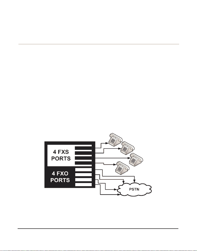
The 800 Series car ds are ver satile de vice s used for connecti ng your phone
network to the PSTN (Public Switched Telephone Network) world. This
is accomplished through phone lines connected to the FXO (Foreign
Exchange Office) ports and phones connected via the FXS (Foreign
Exchange Station) ports. The cards allow Asterisk to connect to your
phone network, creating an office type telephony environment.
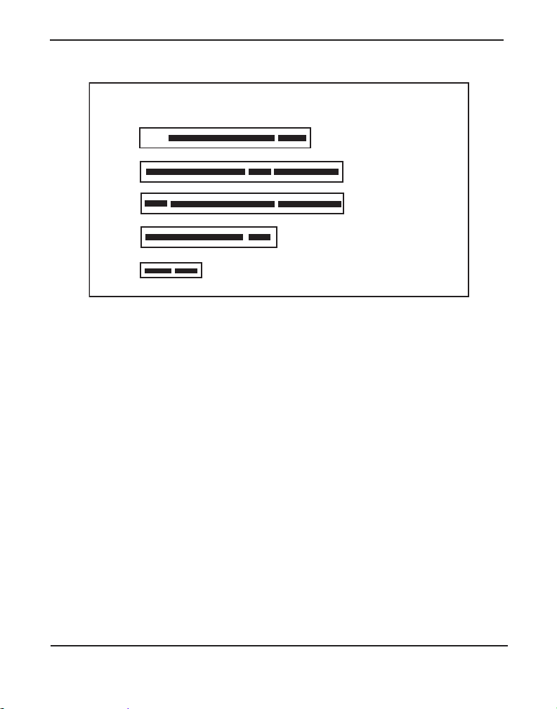
There are a variety of application s where the 800 Series cards (TDM800P
or AEX800) can prove useful. An example is provided in the following
figure.
Figure 1: Sample Card Application
Digiu m, In c . Page 15
Page 16

Chapter 1: Overview
Echo-Cancellation
Users connecting their 800 Series cards to the PSTN or other devices are
likely to be placing calls that will result, at some point, in an unbalanced
4-wire/2-wire hybrid. The result of this hybrid is the reflection of a nearend echo to the calling party. Elimination of this echo is th e responsibility
of echo cancellation.
The 800 Series cards, unless other wise equipped, utilize Asterisk to
perform software-based echo cancellation. Asterisk maintains a number
of open source echo c ancelers. These open source echo cancelers provide
a moderate level of echo cancellation, but are not capable of de aling with
higher levels of, or more advanced, echoes.
Digium recommends that those users concerned about echo cancellation
purchase the VPMADT032 hardware echo cancellation module. The
VPMADT032 may be combined with both the TDM800P and AEX800.
The VPMADT032 is desi gned to h andle up to 128m s of e cho cance llati on
across all channels and provides a G.168 echo cancellation solution.
Digium, Inc. Page 16
Page 17

Chapter 1: Overview
What is Asterisk®?
Asterisk is th e world’s le ading open source telephony engine and tool kit.
Offering fle xibility unheard of in the world of proprietar y
communications, Asterisk empowers developers and integrators to create
advanced communication solutions...for free. Asterisk is r eleased as open
source under the GNU General Public License (GPL), and it is available
for download free of charge. Asterisk is the most popular open source
software avai lable, with the Asterisk Community being the top influencer
in VoIP.
Asterisk as a Switch (PBX)
Asterisk can be configured as the core of an IP or hybrid PBX, switching
calls, managing routes, enabling features, and conne cting callers with the
outside world over IP, analog (POTS), and digital (T1/E1) connections.
Asterisk runs on a wide variety of opera ting systems including Linux,
Mac OS X, OpenBSD, FreeBSD, and Sun Solaris. It provides all of the
features you would exp ect from a PBX inclu ding many adva nced featu res
that are often associate d with high end (and high cost) proprietary PBXs.
Asterisk's archi tecture is designed for maximum flexibilit y and supports
Voice over IP in many protocols, and can interoperate with almost all
standards-base d telephony equipment using relatively inexpensive
hardware.
Asterisk as a Gateway
It can also be built out as the heart of a media gateway, bridging the
legacy PSTN to the expanding world of IP telephony. Asterisk’s modular
architecture a llows it to co nvert between a wide ran ge of communicat ions
protocols and media codecs.
Digium, Inc. Page 17
Page 18

Chapter 1: Overview
Asterisk as a Feature/Media Server
Need an IVR? Asterisk’s got you covered. How about a conference
bridge? Yep. It’s in there. What about an automated at tendant? Asterisk
does that too. How about a replacement for your agi ng legacy voicemail
system? Can do. Unified messaging? No problem. Need a telephony
interface for your web site? Ok.
Asterisk in the Call Center
Asterisk has been adopted by call centers around the world based on its
flexibility. Call center and contact center developers have built complete
ACD systems based on Asterisk. Asterisk has also added new life to
existing call center solutions by adding remote IP agent capabilities,
advanced skills-based routing, predictive and bulk dialing, and more.
Asterisk in the Network
Internet Telephony Service Providers (ITSPs), competitive local
exchange carriers (CLECS ) and even fi rst- tier incu m be nts h av e
discovered the power of open source communications with Asterisk.
Feature servers, hosted services clusters, voicemail systems, pre-paid
calling solution s, a ll based on Asterisk have helped reduce costs and
enabled flexibility.
Asterisk Everywhere
Asterisk has become the basis for thousands of communications
solutions. If you need to communicate, Asterisk is your answer. For more
information on Asteris k, visit http://www.asterisk.org or http://
www.digium.com.
Digium, Inc. Page 18
Page 19

Chapter 2 Card Installation
This chapter provides the following information:
Unpacking the Card on page 20
Shipmen t Ins pec ti o n on page 21
Module Identification on page 21
Port Identi fica ti on on page 21
Card Identification on page 25
FXS and FXO Connection on page 27
Slot Compatibility on page 27
Hardware Installat ion on page 29
Software Installation on page 32
Installing Asteris k on page 36
Digiu m, In c . Pa g e 1 9
Page 20

Chapte r 2: C ar d In st a lla tion
Unpacking the Card
When you unpack your card, carefully inspect it for any damage that may
have occurred in shipment. If damage is suspected, file a claim with the
carrier and contact the reseller from which the card was purchased, or
contact Digium Technical Support at 1.256.428.6161. Keep the original
shipping container to use for future shipment or proof of damage during
shipment.
Note: Only qualified service personnel should install the card. Users
should not attempt to perform thi s function themselves. The installer
must ensure that the equipment is permanently connected equipment,
pluggable type B or connecte d t o a socke t-outle t tha t has bee n checke d
to ensure that it is reliably earthed in accordance with the National
Electrica l Code.
This ca rd is in t en d e d fo r insta ll a ti o n in a R e s t r ic ted Acce ss
Location (RAL) only.
Digium, Inc. Page 20
Page 21

Chapte r 2: C ar d In st a lla tion
Shipment Inspection
The following items are includ ed in shipment of an 800 Series card:
800 Series card (TDM800P or AEX800)
FXO and/or FXS module(s) (depending on configuration)
Module Identification
The 800 Series cards ships with FXO and/or FXS modules in place. These
are identified by their color. Take a moment to identify which modules
were shipped with your card.
FXO (Foreign Exchange Office) modules are Red
FXS (Foreign Exchange Station) modules are Green
See Figure 2 on page 23 for an example of the TDM800P card shown
with two of each single module.
See Figure 3 on page 24 for an example of the AEX800 card shown with
one of each quad module.
The 800 Series cards may also be combined with Digium’s hardwarebased echo cance ler , model VPMADT032. See Figure 3 on page 24 f or an
example of the AEX800 card shown with one of each quad analog
module and the echo cancellation module.
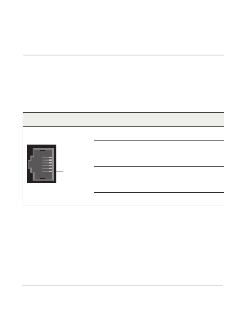
Port Identification
Each card consists of eight RJ11 ports located on the bracket. Each port
correlates to a single m odu l e por t (con tai n in g eith er FX O or FX S
modules). The ports are numbered in s equence from one to eight. The top
port is Port 1 and the bottom port is Port 8. See Figure 2 on page 23 for
Digium, Inc. Page 21
Page 22

Chapte r 2: C ar d In st a lla tion
appropriate ident ification of these ports. The port identif ication is the
same for all cards in this series.
It is important to identify the type and location of your 800 Series
modules. You will need this informat ion dur ing the Asterisk
configuration.
The ports available for use on the 800 Series cards are not continuous.
The ports available for use depend upon the type of module used, and the
placement of the module on the card. The cards can acce pt 2 quad
modules, for a total of 8 ports. If single modules are used, only 2 single
modules can occupy the same spac e as a quad module. The single module
ports are identifi ed on the card and the ir corresponding RJ11 ports a re
identified b elo w. Please refer to Figu re 2 for an exam p le usin g singl e
modules, and Figure 3 for an example using quad modules.
If a single module is used, the RJ11 port available for use will be the port
corresponding to the location of the module on the card. The following
ports correspond to the sing le module ports as shown in Figure 2.
RJ11 Port 1 is used by Single Module Port 1
RJ11 Port 2 is used by Single Module Port 2
RJ11 Port 5 is used by Single Module Port 5
RJ11 Port 6 is used by Single Module Port 6
Digium, Inc. Page 22
Page 23

Chapte r 2: C ar d In st a lla tion
8
All
Ports
Available
1
2
5
6
Single
Modules
Power
Supply
If a quad module is placed cover ing single module ports 1 a nd 2, then that
Figure 2: TDM800P Card with Four Single Modules
module will use ports 1-4. Likewise, if a quad module is placed covering
single module ports 3 and 4, the modul e will use por ts 5 through 8. Figur e
3 shows a AEX800 with two quad modules.
Digium, Inc. Page 23
Page 24

Chapte r 2: C ar d In st a lla tion
Quad
Modules
1
2
3
4
5
6
7
8
Power
Supply
All
Ports
Available
VPMADT032 Echo
Cancellation Module
Digium, Inc. Page 24
Figure 3: AEX800 Card with Two Quad Modules
Page 25

Chapte r 2: C ar d In st a lla tion
Card Identification
There are multiple config urations in which an 800 Series card may be
purchased. Each configuration consists of a combination of single
modules, quad modules, or both, and may also include the VPMADT032
echo cancellation modul e. See Table 1 on page 25 for a list of the most
common TDM800P configurations. See Table 2 on page 26 for a list of
the most common AEX800 config urati ons. The list s are not complete, b ut
rather an example of the configurations available.
It is easie st to identify your c ard by understanding the naming scheme for
each card. The first digit is the maximum port count of the card. The
second digit is the number of FXS (station) modules pr esent on the card.
The third digi t is the numbe r of FXO (office) modules pr esent on the c ard.
Table 1: Example TDM800P Card Configurations
Card ID
FXO/FXS
Ports
TDM801B 1 FXO module
TDM804B 4 FXO modules
TDM808B 8 FXO modules
TDM844B 4 FXS and 4 FXO modules
TDM880B 8 FXS modules
Digium, Inc. Page 25
Page 26

Chapte r 2: C ar d In st a lla tion
Table 2: Example AEX800 Card Configurations
Card ID
FXO/FXS
Ports
AEX801B 1 FXO module
AEX804B 4 FXO modules
AEX808B 8 FXO modules
AEX844B 4 FXS and 4 FXO modules
AEX880B 8 FXS modules
Digium, Inc. Page 26
Page 27

Chapte r 2: C ar d In st a lla tion
FXS and FXO Connection
The 800 Series cards provide eight RJ1 1 c onnectors for access to the FXS
and/or FXO modules installed in the available slots. The diagram in
T able A-1 on page 57 provides the pinout for this connec tor.
Caution.
Only qualified service personnel should continue with
hardware installation and configuration of the 800 Series card.
Users should not at tempt to perf orm t hese f unct ions th emselve s.
Slot Compatibility
Check the type of card you received to be sure it is compatible with your
PCI slot. To determine which slot you have, identify it by c omparing it to
those shown in Figure 4 on page 28.
Slot Number:
0: AGP Pro Slot
1: 64-bit 5.0 volt PCI Slot
2: 64-bit 3.3 volt PCI Slot
3: 32-bit 5.0 volt PCI Slot
4: PCI Express Slot
Digium, Inc. Page 27
Page 28
Chapte r 2: C ar d In st a lla tion
0
1
2
3
4
Slots
Figure 4: Motherboard Slots
The TDM800 card is a 32-bit 33MHz card keyed for universal 3.3 volt or
5.0 volt operation and works in any PCI 2.2 (or greater) compliant slot.
This means that in t he motherboard shown in Figure 4, the TDM800 card
will fit into Slots 1, 2, or 3 (PCI slots), but will not fit int o S l ot 0 ( A GP
slot) or Slot 4 (PCI Express slot).
The AEX800 card is a PCI Express card. Slot 4, illustrated above, is a 1
lane (X1) PCI Express compliant slot. The AEX800 will work in any PCI
Express compliant slot, including lane lengths X4, X8, and X16. This
means that in the motherboard shown in Figur e 4, the AEX800 will only
fit into Slot 4. The AEX800 can not be used in Slots 0 through 3.
Digium, Inc. Page 28
Page 29

Chapte r 2: C ar d In st a lla tion
Hardware Installat ion
1. Now that you are acquainted with your card, power down your com-
puter and unplug it from its power source.
2. Attach a static strap to your wrist and open the case.
3. Remove the bracket place holder and insert the card into a PCI
(TDM800P) or PCI Express (AEX800) slot. See Figure 5.
Figure 5: Insert the Card
4. If your card has any FXS modules, you will also need to connect the
power cable from your computer’s power supply to the back of the
card. Insert a four-pin 12 volt connector (disk drive power supply
cable, e.g. hard drive) into the white plastic connector on the rear of
the ca rd. See Figure 6.
Digium, Inc. Page 29
Page 30

Chapte r 2: C ar d In st a lla tion
Figure 6: Connect Power for FXS Modules
Many modern PCs and servers do not have either spa re or any 12V power
connectors. If you have FXS modules on your card and your compute r
does not have power cables available , then power must be provided to the
800 Series card by an alternate means. Digium provides a solution to this
problem with the optional PWR2400B (a vailable separately ). This card is
essentially a PCI bracket as se mbly that takes power from an external DC
power supply and routes it to two 15" power cables inside the computer .
You must have an available bracket slot to use the PWR2400B (either
PCI, PCI Express or AGP).
A strap on the PWR2400B card allows the two power cables to take
power from the same DC s upply. The PWR2400B comes with one power
supply capable of supporti ng up to 24 FXS ports each, dr iving heavy
loads of up to 5REN. If more than 24 FXS ports with heavy loads are
connected to t he PWR2400B, the n a sec ond Di gium power Suppl y shoul d
Digium, Inc. Page 30
Page 31

Chapte r 2: C ar d In st a lla tion
be purchased. The shorti ng strap on the PWR2400B should be removed if
a second power supply is used.
The PWR2400B does not connect to any bus inside the computer. It may
be used where ver there is an available PC I-s i ze brac ket such as a PCI,
PCI Express, or AGP slot.
Note: The PWR2400B is not intended to supply power to any other
device, it is intended only to be used with UL Listed Digium analog
cards.
5. Replace the cover to your computer.
Electrical Shock.
To re duce the risk of injury, damage to the unit or your
equipment, do not attempt to apply power to the unit while the
case is open. Pe rsonal injury or damage to the unit could occur
if the modules are touched while powered is applied.
6. Plug all outside phone lines to the FXO (red) ports and connect all
phones to the FXS (green) ports as needed usin g a patch panel or
punch block. See Table A-1 on page 57 for the pin assignments.
Caution.
This unit must be connected to the Telecommu nications
Network in your country using an approved line cord, e.g. : for
Australia use only line cords complying with ACA Technical
Standard TS008.
Caution.
Only connect regulatory equipment (approved for use in your
specific country) to the telecommunications network voltage
circuit ports.
Digium, Inc. Page 31
Page 32

Chapte r 2: C ar d In st a lla tion
Softw a r e In s t al la t io n
Digium hardware requires driver s and libraries that are not integrated
with the Linux kernel. Digium hardware is only supported under Linux.
Digium recommends CentOS, Debian, R ed Hat, and Ubuntu distribut ions
of Linux. However, many other distributions are supported by Digium
Technical Support.
Digium’s software, including drivers and application software, may be
obtained from Digium’s download server at:
http://downloads.digium.com
For an introduction to Asterisk, Digium’s telephony software, including
additional infor mation on its configuration, setup, and features, please
refer to:
http://www.asterisk.org
For the latest information on se tting up and configuring DAHDI drivers
for your Digium hardwar e product, please refer to t he lat est relea se of t his
manual which is available fro m the product-specific documentation
section at:
http://www.digium.com
To install your 800 Series card, you will need:
Linux 2.6 kernel headers
Development librarie s and head ers for ncurses
Development librarie s and head ers for zlib and openssl
Development librarie s and headers for newt
GCC and standard software build tool s
It is recommended that you use the most recent version of the Asterisk,
DAHDI, and libpri software for the best results. If you have previously
Digium, Inc. Page 32
Page 33

Chapte r 2: C ar d In st a lla tion
installed any of these, Digium recommends that you upgrade to the latest
“-current” version of each.
Note: If you are using the 1.4.x series of Asterisk, you will need
Asterisk 1.4.22 or newer.
1. After the machine has booted to Linux, log in and execute the follow-
ing command to list the devices detected by the PCI bus:
# lspci -n
Confirm that the output from lspci lists a device with Digium’s PCI
vendor ID which is “d161”. The screen output should be simila r to the
following:
0000:01:00.0 0200:d161:<card identifier>
Note: The output from lspci may or may not state “Unknown
device”. If it does, this does not indicate a problem.
In the PCI device listing shown above, <card identifier> will be
populated with one of the identifiers listed in the table below.
Digium, Inc. Page 33
Page 34

Chapte r 2: C ar d In st a lla tion
Table 3: Card Identifiers
Model Identifier
TDM800P
AEX800
0800
8002
A Digium 800 Series (TDM800P/AEX800) card identifier should be
listed. If a matching card identifier is not listed, then your machine is
not PCI 2.2 (or higher) or PCI Express compatible, and the card will
not work with your motherboard.
2. Download the latest DAHDI drivers with tools. DAHDI is available
for download from:
http://downloads.digium.com/pub/telephony/dahdi-linux-complete
# wget http://downloads.digium.com/pub/telephony/
dahdi-linux-complete/dahdi-linux-completecurrent.tar.gz
Digium, Inc. Page 34
Page 35

Chapte r 2: C ar d In st a lla tion
3. Expand the dow nl oad ed file , compile its content s, and ins tal l the
drivers and tools. Substitute the version of DAHDI for the X.X.X in
the command lines below.
# tar -zxvf dahdi-linux-complete-current.tar.gz
# cd dahdi-linux-complete-X.X.X+X.X.X
# make
# make install
# make config
Note: Executing ‘make config’ will install an init script and symlinks
which will allow you to start and stop DAHDI as a service.
Digium, Inc. Page 35
Page 36

Chapte r 2: C ar d In st a lla tion
Installing Asteris k
If you wish to use Asterisk with your new hardware, you can follow the
instructions below.
1. Download the latest relea se version of Aste risk, either 1.4.22 ( or later)
or 1.6.0.1 (or later). Substitute the version of Asterisk for the X.X in
the command below. Asterisk is available for downloa d from:
http://downloads.digium.com/pub/telephony/asterisk
# wget http://downloads.digium.com/pub/telephony/
asterisk/asterisk-X.X-current.tar.gz
2. Expand the dow nl oad ed file , compile its content s, and ins tal l the
application. Substitute the version of Asterisk for the the X.X and
X.X.X in the command lines below.
# tar -zxvf asterisk-X.X-current.tar.gz
# cd asterisk-X.X.X/
# ./configure
# make menuselect
# make
# make install
Digium, Inc. Page 36
Page 37

Chapte r 2: C ar d In st a lla tion
3. If this i s the fir st Aste risk i nstall at ion on th is s ystem, you sho uld install
the sample configurati on files. To do this, run:
# make samples
Note: Running this command will overwrite, after making a backup
copy, any older Asterisk configura tion files that you have in the /etc/
asterisk directory.
If your installation has failed, it may be because you are missing one
or more of the build dependencies, the kerne l headers, or the
development tools. Please contact your reseller where the card was
purchased, or call Digium Technica l Support at 1.256.428.6161 for
assistance.
Complete instructi ons for installing Asterisk are available at
www.asterisk.org
.
Digium, Inc. Page 37
Page 38

Chapter 3 Configuration
The 800 Series cards have a vari ety of configur atio n option s. This c hapter
provides sample configur ations to demonstrate customizing the Asterisk
software to meet your individu al needs. Each section explains basic
options as examples. Once you have familiarized yourself with the
samples, you can edit the configura tion files to meet your specific needs.
Digiu m, In c . Pa g e 3 8
Page 39

Driver Configuration
Chapter 3: Configuration
1. Begin by opening the system.conf file from the
/etc/dahdi directory.
2. Specify the two lett er country c ode for your loa dzone and defaultz one.
This will preload tone zone data and specif y a def ault tone zone for
your interfaces.
The following is a typical setup for a telco in the US:
loadzone = us
defaultzone = us
Digium, Inc. Page 39
Page 40

Chapter 3: Configuration
3. Specify the channel definitions. The format is:
<device> = <channel list>
A list of valid devices are specified in the sample system.conf file.
If your card has any red FXO modules, add the following to
system.conf:
fxsks =
fxsks uses kewlstart signalling, which is loopstart signalling with disconnect
supervision. For example, a TDM808E card would be configured as the
following:
fxsks = 1-8
OR
fxsks = 1,2,3,4,5,6,7,8
You should have ide ntified the type of 800 Series c ard whe n you r eceived it.
If you are not sure, refer to
assistance.
Module Identification on page 23 for
Note: The 800 Series cards do not support Ground Start signaling.
Digium, Inc. Page 40
Page 41

Chapter 3: Configuration
4. If your card has any green FXS modules, add the following:
fxoks =
fxoks uses kewlstart signa lling, which is loopstart signalling with
disconnect supervision. For example, a TDM880E card would be
configured as the following:
fxoks = 1-8
OR
fxoks = 1,2,3,4,5,6,7,8
5. An example TDM844E card configuration would be:
fxoks = 1-4
fxsks = 5-8
OR
fxoks = 1,2,3,4
fxsks = 5,6,7,8
6. DAHDI uses modular echo cancellers that are configured per channel.
The echo cancellers are compiled and installed as part of the dahdilinux package. You can specify the echo canceller to be used for each
channel. The default behavior is for there to be no echo canceller on
any channel. So, it is very important that you specify one in the
Digium, Inc. Page 41
Page 42

Chapter 3: Configuration
system.conf file if you do not have ha rdware echo canceller s and need
echo cancel latio n . Th e format is:
echocanceller = <echocanceller name>,<channel(s)>
A list of valid echo cancellers are specified in the sample system.conf
file.
The following is a typical setup using software-based echo
cancellation:
echocanceller = mg2,1-8
7. Load DAHDI drivers into the kernel using the modprobe utility. The
appropriate driver for the 800 Series cards is wctdm24xxp. Users
should use the following modprobe command:
# modprobe wctdm24xxp
# dahdi_cfg -vv
# dmesg
Note: The 800 Series cards use the same driver as the TDM2400.
Digium, Inc. Page 42
Page 43

Chapter 3: Configuration
Figure 7: Example dmesg Screen Shot
Note: Output as shown above may vary depending on the 800 Series
card you use.
Digium, Inc. Page 43
Page 44

Chapter 3: Configuration
Configuring Card Features
You will need to modify the chan_dahdi.conf f ile which is located in the
/etc/asterisk directory in order to configure the essential features of your
card. This file is the configuration layer between DAHDI and Asterisk.
The following is a sample configuration for a TDM844E card. You can
place this at the bottom of your
;General options
usecallerid = yes
hidecallerid = no
callwaiting = yes
threewaycalling = yes
transfer = yes
echocancel = yes
echocancelwhenbridged = yes
rxgain = 0.0
txgain = 0.0
;FXS Modules
group = 1
signalling = fxo_ks
context = Internal
channel = 1-4
chan_dahdi.conf file.
;FXO Modules
group = 2
echocancel = yes
signalling = fxs_ks
context = Incoming
Digium, Inc. Page 44
Page 45

Chapter 3: Configuration
channel = 5-8
Users of Digium 's ha rdware e cho ca ncel lation module, t he VPMADT032,
should set the echocancel option to "yes." The module will automatically
configure itself to run at full capacity, 1024 taps (128ms), on each
channel.
Users without the VPMADT032 using open source echo cancelers
included with DAHDI should configur e echocancel to the values 128
(16ms) or 256 (32ms). Setting "yes" will default the option to 128 (16ms).
Users who have no t purchased an 800 Seri es card with the hardwa re e cho
cancellation module are encouraged to take advantage of Digium's High
Performance Echo Canceler software. This commercially licensed
software, which is made available at no charge to in-warranty Digium
analog interface card customers, provide toll quality echo cancella tion,
performed on the host CPU, at up to 1024 taps (128ms) per channel. For
further details about HPEC, please refer to the Digium website here:
http://www.digium.com/en/products/software/hpec.php
When HPEC is enabled, users may set the value of the echocancel
parameter to any of the following val ues:
128 - 16ms
256 - 32ms
512 - 64ms
1024 - 128ms
Note: Higher values will result in dramatically increased CPU
consumption. In order to optimize system performance, users are
encouraged to choose the minimum value required to cancel their
echo.
Digium, Inc. Page 45
Page 46

Chapter 3: Configuration
Voicemail
voicemail.conf and find the following line at the bottom:
Open
[default]
1234 => 4242,Mark Spencer,root@localhost
In this example, 1234 is the mailbox number, 4242 is the password, Mark
Spencer
is the person’s name, and root@localhost is his email add ress .
You can add extensions by adding the following:
1000 => 1234,Moose Member,moose@digium.com
2000 => 1234,Bill Savage,bsavage@digium.com
Digium, Inc. Page 46
Page 47

Chapter 3: Configuration
Dial Plan
extensions.conf, which contains a large, complex sample dial
Open
plan. In this step, you will configure a basic dial plan to enable you to
send and receive calls. Go to the bottom of the file and add the following
lines:
[Internal]
exten => 1000,1,Dial(DAHDI/1,20,rt)
exten => 1000,2,Voicemail(1000,u)
exten => 1000,102,Voicemail(1000,b)
exten => 2000,1,Dial(DAHDI/2,20,rt)
exten => 2000,2,Voicemail(2000,u)
exten => 2000,102,Voicemail(2000,b)
exten => 8500,1,VoiceMailMain
exten => 8501,1,MusicOnHold
exten => _9.,1,Dial(DAHDI/g2/www${EXTEN:1})
exten => _9.,2,Congestion
[Incoming]
exten => s,1,Answer
exten => s,2,Dial(DAHDI/g1,20,rt)
exten => s,3,Voicemail(1000,u)
exten => s,103,Voicemail(1000,b)
Digium, Inc. Page 47
Page 48

Chapter 3: Configuration
In this example there are two interna l ext ensions (1000 and 2000), a
number to check voicemail (8500) , a number to listen to music-on-hold,
(8501), and a prefix to dial to get an outside line (9). It is configured to
accept incoming calls over the FXO, rin gs phones 1 and 2, and route to
voicemail box 1000.
T esting Your Configuration
1. Start Aste r isk by typing:
asterisk
2. Connect to Asterisk and view the output by typing:
asterisk -vvvvr
3. Dial tone should be present on phones connected to the FXS ports.
Test your configuration by placing an outgoing call, placing a call
from extension 1 to 2, or receiving an incomin g call. Successful
completion of these tasks indic ates your configuration is working
properly.
Digium, Inc. Page 48
Page 49

Chapter 3: Configuration
Figure 8: Sample Application
Note: More detailed information is provided at the Asterisk website
(www.asterisk.org), as well as the Digium Knowledge Base
(kb.digium.com). You may also obtain assistance by contacting
Digium T echn ical Suppor t at 1.256.428. 6161 or visitin g the website at
www.digium.com
.
Digium, Inc. Page 49
Page 50

Chapter 4 FXS and FXO Explained
Identification
There are multiple standa rd conf igurations in which an 800 Series card
may be purchased. Each configuration consi sts of one to four FXS and/or
FXO modules. These modules are identified by their color.
FXS - Foreign Exchange Station (Green Modules )
FXO - Foreign Exchange Office (Red Modules)
This chapter provides an in-depth review of the two module types and
their uses within your Aster isk server.
Note: Only qualified service personnel should install the card. Users
should not attempt to perform thi s function themselves.
FXS Module
The FXS module allows an 800 Series card to initiate and send ringing
voltage to an FXO device such as an analog telephone.
FXO Module
The FXO module allows an 800 Series c ard to te rminate analog te lephone
lines (POTS). Because of the modular design, you can activate additional
ports at any time with more FXS or FXO daughter cards. The FXO
module passes all the call feat ures any standa rd analog teleph one line will
support. The phone receiving the call is the last FXO device in the chain.
When it receives voltage from an FXS device, the phone rings.
Digiu m, In c . Pa g e 5 0
Page 51

Chapter 4: FXS and FXO Explained
Using Your 800 Series Card
Connect the ou tside line to an F XO port on you r Aste risk server to r eceive
voltage from the outside lines.
Connect the phones to FXS ports on your As terisk server. When the FXO
module in your Asterisk Server receives the voltage, it will then generate
voltage using the FXS module and send it to your analog phone.
Digium, Inc. Page 51
Page 52

Chapter 5 Troubleshooting
This chapter provides frequent ly asked questions a nd possible resolutions
as identified by Digium Technical Support. Multiple resources are
available t o obtai n mor e infor mation a bout Asterisk and Digium produc ts.
Please visit both www.digium.com and www.asterisk. org for more
information.
Digiu m, In c . Pa g e 5 2
Page 53

Chapter 5: Troubleshooting
The FXO module never seems to hang-up the line. How do I set it to hang-up?
busydetect = yes and busycount = 10 in the chan_d ahdi.co nf for
Set
your channels. This will cause the line to hang-up by listening for a
consecutive number of busy tones. Upon editing
chan_dahdi.conf, you
will need to restart Aster isk.
I have echo problems on my FXO modules and I've tried the different echo cancellation algorithms in dahdi_config.h, tried tweaking the gains, and still nothing works. What can I do?
Run the fxotune utility with th e -i option (fxotu ne -i 4). It should discover
which DAHDI channels are FXO modules and tune them accordingly. Be
warned however , it takes a significant amount of time for each modul e to
tune. A conservative estimate would be somewhere around 2-3 minutes
for each module. You only have to tune the channels once for each line.
The fxotune utility will store the calibration settings in /etc/fxotune.conf.
You will need to configure your system to run fxotune with the -s flag
(fxotune -s) during the Linux boot se quence in order to initialize the
previously discovered values which are stored in fxotune.conf. A
recommendation is to put ‘f xotune - s’ in y our distrib ution’s startup scripts
at some point after the DAHDI module loads and before Asterisk
executes.
Note: The digit after the -i option is the digit that will break dialtone
on the line.
There is a slight echo. How can I adjust the sound quality?
Digium, Inc. Page 53
Page 54

Chapter 5: Troubleshooting
There are several options available to correct this. Each involves editing
the
chan_dahdi.conf file. Be sure to restart Asterisk upon completion.
1. Adjust echocancel = yes to one of the following valu es: 32, 64, 128,
.
or 256
2. Yo u can al so set
3. Yo u can al so adj u st the
echotraining = yes.
rxgain and the txgain, although it is only
recommended to shift between -5 and 5.
How can I enable more features?
To view all of the options available to add to your dial plan, type the
following commands from within Aster isk:
*CLI> core show applications
*CLI> core show functions
Digium also offers services to help configure and add features you might
need. Contact Digium Technical Suppor t at 1. 877.DI GIUM.1
(1.877.344.4861) for more information.
Digium, Inc. Page 54
Page 55

Chapter 5: Troubleshooting
Common Fixes
1. Check to see if the X W indow System (e.g. X.Org Server) is running
by entering the following:
# ps aux | grep X
If the X Window System is running, stop the application since it may
cause a conflict with Asterisk.
2. Check to see if your PATA IDE hard drives are running with DMA
levels set. Advance user can perform an
hdparm on your hard drive
interface.
Use hdparm with caut ion as t he man pa ge st ates that h ar d drive
corruptio n can occur when using incorrect settings. Pl ease
review t he man page for hdp arm and mak e sur e you unde rst and
the risks before using this tool.
Check the current mode using this command:
hdparm -vi /dev/[IDE Device]
Use this command to set the drives into UDMA2 mode:
hdparm -d 1 -X udma2 -c 3 /dev/[IDE Device]
If you ar e still havin g problems, contact your resell er from which t he card was purchased, or Digium Technical Support at 1.877.DIGIUM.1 (1.877.344.4861).
Digium, Inc. Page 55
Page 56

Chapter 5: Troubleshooting
Where can I find answers to additional questions?
There are several places to inquire for more information about Asterisk
Digium products:
1. Digium Technical Support (+1.256.428.6161), or Toll Free in the U.S.
(1.877.344.4861), is available 7am-8pm Central Time (GMT -6),
Monday - Friday.
2. Asterisk users mailing list (asterisk.org/lists.digium.com
3. IRC channel
#asterisk on (irc.freenode.net).
).
Subscription Services Program
Digium is dedicated to support ing your Asterisk system by offering full
technical support through our Subscription Services Program. Through
this program, you can be at ease knowing that your business will always
have access to the Asterisk expert s. Prici ng on Subscription Servic es may
be obtained from your nearest reseller or you may call Digium Sales for
referral to your neares t rese ller at +1.256.428.6000 or e-mail
sales@digium.com.
Digium, Inc. Page 56
Page 57
Appendix A
Pin 1
Pin 6
Pin Assignments
All eight ports on the 800 Series card’s bracket are 6-pin RJ11 ports. The
pin assignments are identif ied in Ta ble A-1.
Table A-1: RJ11 Telco Port Connector
Pin Description
1 Not used
2 Not used
3Tip
4Ring
5 Not used
6 Not used
Digiu m, In c . Pa g e 5 7
Page 58

Appendix B Specifications
This appendix provides specifications, required environmental
conditions, and maximum power consumption for the 800 Series
cards.
Physical (All Cards).
Size: 6.48” × 4.2” × 0.68” (16.46 x 10.67 x 1.72 cm)
PCB size, does not include the PCI bracket.
Check your model carefully to be sure it will accept
this PCI card.
Weight: 4.5 oz (127.58 gm) with no modules loaded
Each quad module adds 1 oz (28.35 g)
Interfaces.
Local Loop Access: Industry standard 6-pin RJ-1 1.
(TDM800P) - PCI Bus: 3.3V or 5V bus slot, half-length ful l-height PCI
card, 33MHz minimum bus speed, compliant with PCI 2.2 or greater.
Additional Power: four -pin 12V connector for FXS power supply
(required only if FXS modules are installed)
(AEX800) - PCI-E X1, compliant with PCI-E X1 1.0 or greater.
Digiu m, In c . Pa g e 5 8
Page 59

Appendix B: Specifications
Environment.
Temperature: 0 to 50° C (32 to 122° F) operation
-20 to 65° C (-4 to 149° F) storage
Humidity: 10 to 90% non-condensing
Note: Operating temperature is limited to 0 to 40° C (32 to 104°F)
when used with optional PWR2400B Power Bracket
Hardware an d Softw a re Requirements.
500-Mhz Pentium III or better
64MB RAM
Available PCI or PCI-Express Slot (as described previously)
Power Cons u m pti on.
The following table lists the power consumption for both the TDM800P
card (and its permutations) and the AEX800 card (and its permutations).
Note: 3.3 and 5 vo lt po wer is ta ken f rom the PCI s lot. 12 volt power i s
taken only from the four -pin hard disk drive connector or optional
PWR2400B.
Digium, Inc. Page 59
Page 60

Appendix B: Specifications
Table B-2: Maximum Power Consumption
Model Power
3.3V All TDM models 1W
3.3V All AEX “B” models 3.5 W
3.3V All AEX “E” models 4.5 W
5.0V All TDM “B” models 1W
5.0V All TDM “E” models 9W
5V All AEX models 0W
12V AEX/TDM804E 0W
AEX/TDM808E into 1REN 0W
AEX/TDM844E into 2REN 6.5W
AEX/TDM840E into 3REN 6.5W
AEX/TDM880E into 5REN 13W
Digium, Inc. Page 60
Page 61

Appendix C Gloss ary and Acronyms
ANSI American National Standards Institute
An organization which proposes and establishes standards for
international communications.
asynchronous
Not synchronized; not timed to an outside clock source. Transmission is
controlled by start bits a t the beginning and stop bits at the end of each
character. Asynchronous communica tions are often found in internet
access and remote office applications.
attenuation
The dissipation of a transmitted signal’s power as it travels over a wire.
bandwidth
The capacity to carry traffic. Higher bandwidth indicates the ability to
transfer more data in a given time period.
bit
The smallest element of information in a digital system. A bit can be
either a zero or a one.
bps bits per second
A measurement of transmission spe ed across a data connection.
Digiu m, In c . Page 61
Page 62

Appendix C: Glossary and Acronyms
broadband
Broadband transmission sha res the bandwidth of a particular medium
(copper or fiber optic) to integrate multiple signals. The channels take up
different f requencies on the cable, integrating voic e, data, and video over
one line.
channel
A generic term for an individual dat a stre am. Ser vice providers can use
multiplexing techniques to transmit multiple channels over a common
medium.
Cat5
Category of Performance for wiring and cabling. Cat 5 cabling support
applications up to 100 MHz.
Cat5E
Category of Performance for wiring and cabling. Category 5 Enhanced
wiring supports signal r ates up to 100 MHz but adheres to stricter quality
specifications.
CLEC competitive local exchange carrier
A term for telephone companies established after the
T elecommunications Act of 1996 deregulated the LECs. CLECs compete
with ILECs to offer local service. See als o LEC and ILEC.
Digium, Inc. Page 62
Page 63

Appendix C: Glossary and Acronyms
CO central office
The CO houses local switching equipment. All local access lines in a
particular geographic area terminate at this facility (which is usually
owned and operated by an ILEC).
CPE customer prem ises equipment
T erminal equipment which is connected to the telecommunications
network and which resides within the home or of fice of the customer . This
includes telephones, modems, terminals, routers, and television set-top
boxes.
DAHDI Digium Asterisk Hardware Device Interface
A telephony project dedicated to implementing a reasonable and
affordable compute r tele phony plat form in to t he wor ld mar ketpla ce. Al so,
the collective name for the Digium -provided drivers for Digium
telephony interface products.
DS0 Digital Signal, Level 0
A voice grade channel of 64 Kbps. The worldwide standar d speed for
digitizing voice conversation using PCM (Pulse Code Modulation).
DS1 Digital Signal, Level 1
1.544 Mbps in North America (T1) and Japan (J1) -up to 24 voice
channels (DS0s), 2.048 Mbps in Europe (E1) - up to 32 voice channels
(DS0s). DS1/T1/E1 lines are part of the PSTN.
Digium, Inc. Page 63
Page 64

Appendix C: Glossary and Acronyms
DS3 Digital Signal, Level 3
T3 in North America and Japan, E3 in Europe. Up to 672 voice channels
(DS0s). DS3/T3/E3 lines are not part of the PSTN.
DTMF Dual Tone Multi-Frequency
Push-button or touch tone dial ing.
E1
The European equivalent of North Ameri can T1, transmits data at 2.048
Mbps, up to 32 voice channels (DS0s).
E3
The European equival ent of North American T3, transmits data at 34.368
Mbps, up to 512 voice channels (DS0s). Equivale nt to 16 E1 lines.
EMI Electromagnetic Interference
Unwanted electrical noise present on a power line
full duplex
Data transmission in two directions simultaneously.
FXO Foreign Exchange Office
Receives the ringing voltage from an FXS device. Outside lines are
connected to the FXO port on your 800 Series card.
Digium, Inc. Page 64
Page 65

Appendix C: Glossary and Acronyms
FXS Foreign Exchange Station
Initiates a nd sends ringin g vol tage. P hones ar e c onnected to t he FXS ports
on the 800 Series card.
G.711
A recommendation by the Telecommunication Standardization Sector
(ITU-T) for an algorithm designe d to transmit and receive mulaw PCM
voice and A-law at a digita l bit rate of 64 Kbps. This algor ithm is used fo r
digital telephone sets on digital PBX.
G.723.1
A recommendation by the Telecommunication Standardization Sector
(ITU-T) for an algorithm designe d to transmit and receive audio over
telephone lines at 6.3 Kbps or 5.3 Kbps.
G.729a
A recommendation by the Telecommunication Standardization Sector
(ITU-T) for an algorithm designe d to transmit and receive audio over
telephone lines at 8 Kbps.
H.323
A recommendation by the Telecommunication Standardization Sector
(ITU-T) for multimedia communic ations over packet-based networks.
IAX Inter - A steri sk eXchange
The native VoIP protocol used by Asterisk. It is an IETF standard used to
enable VoIP connections between Asterisk servers, and between servers
and clients that also use the IAX protoc ol.
Digium, Inc. Page 65
Page 66

Appendix C: Glossary and Acronyms
iLBC internet Low Bitrate Codec
A free speech codec used for voice over IP. It is designed for narrow band
speech with a payload bitrate of 13.33 kbps (frame length = 30ms) and
15.2 kbps (frame length = 20 ms).
ILEC incumbent local exchange c arrier
The LECs that were the or iginal carr iers in the market pr ior to th e entry of
competition and theref ore have the dominant position in the market.
interface
A point of contact between two systems, networks, or devices.
ISO International Standards Organization
LED light-emitti ng diode
Linux
A robust, feature-packed open source operating system based on Unix
that remains freely available on the internet. It boasts dependability and
offers a wide range of compatibility with hardware and software. Asterisk
is supported exclusively on Linux.
loopback
A state in w hich the transmit signal is reversed back as the receive signal,
typically by a far end network element.
Digium, Inc. Page 66
Page 67

Appendix C: Glossary and Acronyms
MGCP Media Gateway Control Protocol
multiplexing
Transmitting multiple signals over a single line or channel. FDM
(frequency divisi on multiplexing) and TDM (time division multiplexi ng)
are the two most common methods. FDM separates signals by dividing
the data onto different carrier frequencies, and TDM separates signals by
interleaving bit s one after the other .
MUX multiplexer
A device which transmits multipl e signals over a single communications
line or channel. See multiplexing.
PBX private branch exchange
A smaller version of a phone company’s large centra l switching office.
Example: Asterisk.
PCI peripheral component interconnect
A standard bus used in most computers to connect peripheral devices.
POP poin t of presence
The physical connection point between a network and a telephone
network. A POP is usually a network node serving as the equivalent of a
CO to a network service provider or an interexchange carrier.
POTS plain old telephone service
The public switched teleph one network (PSTN) is the network of the
world's public circuit-switched telephone networks. Originally a network
Digium, Inc. Page 67
Page 68

Appendix C: Glossary and Acronyms
of fixed-line analog te lephone systems, the PSTN is now almost entirely
digital, and now includes mobile as well as fixed telephones.
PPP point-to-point protocol
Type of communications link that connects a single device to another
single device, such as a remote terminal to a host computer.
PSTN public switched telephone network
A communications network which uses telephones to establish
connections between two poin ts. Also referred to as the dial network.
QoS quality of service
A measure of telephone service, as specified by the Public Service
Commission.
RJ11
A six-pin ja ck typically used for connecting telephone s, modems, and fax
machines in residentia l and business settings to PBX or the local
telephone CO.
SIP Session Initiation Protocol
An IETF standard for setting up sessions be tween one or more clients. It
is currently the leading signaling protocol for Voice over IP, gradually
replacing H.323.
Digium, Inc. Page 68
Page 69

Appendix C: Glossary and Acronyms
T1
A dedicated digital carrier facility which transmits up to 24 voice
channels (DS0s) and transmit s data at 1.544 Mbps. Commonly used to
carry traff ic to and from private business networks and ISPs.
T3
A dedicated digital carrie r facility which consists of 28 T1 lines and
transmits data at 44.736 Mbps. Equivalent to 672 voice channels (DS0s).
TDM time division multiplexer
A device that supports simul taneous transmissi on of multiple data streams
into a single high-speed dat a stre am. TDM separa tes signals by
interleaving bit s one after the other .
telco
A generic name which refers to the telephone companies throughout the
world, including RBOCs, LECs, and PTTs.
tip and ring
The standard terminati on on the two conduct ors of a telephone circuit;
named after the physical appear a nce of the contact areas on the jack plug.
twisted pair
T wo copper wires commonly used for telephony and data
communications. The wires are wrapped loosely around each other to
minimize radio frequency interference or interference from other pairs in
the same bundle.
Digium, Inc. Page 69
Page 70

Appendix C: Glossary and Acronyms
V volts
VoIP Voice over IP
T echnology used for transmitti ng voice traffic over a data network using
the Internet Protoco l.
Digium, Inc. Page 70
 Loading...