

Page 1

Analog 410 Series
TDM410/AEX410
User Manual
601-00006 Rev. C1
Page 2

Digium, In c.
445 Jan Davis Dri ve
Huntsville, AL 35806
United States
Main Number : 1.2 56.428.6000
Tech Support: 1.256.428.6161
U.S. Toll Free: 1.877.344.4861
Sales: 1.2 56.428.6262
www.digium.com
www.asterisk.org
www.asterisknow.org
© Digium, Inc. 2011
All rights reserved.
No part of this publication may be copied, distributed, transmitted, transcribed, stored in a
retr iev al syst em , or t ran sl ated int o any huma n or co mpute r langu ag e wit h out t he prio r writt e n
permission of Digium, Inc.
Digium, Inc. has made every effort to ensure that the instructions contained in this document
are a de quat e an d er ro r fr ee . T he m a nu f a ctu r e r w i ll, if n ec es s ary , ex pl ai n issu es w h ic h may
not be covered by this documentation. The manufacturer’s liability for any errors in the
docu ments is limited to the correction of er rors and the afo rementioned advisory services.
This docume nt has be en prep ared for use by pro fessio nal and p roperl y train ed perso nnel,
and th e cus to mer assumes full resp on si bilit y whe n us ing it.
Adobe and Acrobat are registered trademarks, and Acrobat Reader is a trademark of Adobe
Systems Incorporated.
Asterisk, Digium, Switchvox, and AsteriskNOW are registered trademarks and Asterisk
Business Edition, AsteriskGUI, and Asterisk Appliance are trademarks of Digium, Inc.
Any o th er tr a demar k s m en tion ed i n the do cu me nt a r e th e pr oper t y of t h ei r r es pec tiv e own er s.
Digium, Inc. Page 2
Page 3

Safety Certi fication and Agency Approvals
Safety: US/CSA 60950
IEC 60950
EN 60950
Other:
CE Mark
2002/95/EC R estric tions on Haza rdous S ubstance s (Ro HS), 2005/ 747/EC
lead free exemption (Annex C)
Telecom:
FCC Part 68, ANSI/TIA-968-A, Including Amendment A1 and A2
Industry Canada IC-CS-03
Australi a S002 (POTS line) / S003 (POTS Extn)
TBR-21
EMC:
FCC Part 15 Class A
EN55022/CISPR22 Class A
EN55024
Digium, Inc. Page 3
Page 4

Federal Communications Commission Part 68
This equipment complie s with Part 68 of the FCC rules and the
requireme nts adop ted by the AC TA. On the back of the Analog 410 Series
printed cir cuit board is a label that contains, among other infor mation, a
product identif ier in the format US:AAAEQ##TXXXX. If requested, this
number must be provided to the tele phone company.
A plug and jack used to connect this equ ipment to the premises wiring
and telephone network must comply with the applicable FCC Part 68
rules and requirements adopted by the ACTA.
The REN is used to determine the number of devices that may be
connected to a telephone line. Excessiv e RENs on a telephone line may
result in the devi ces not ringing in response to an incoming call. In most
but not all areas, the sum of RENs should not exceed five (5.0). To be
certain of the number of devices that may be connected to a line, as
determined by the total RENs, contact the local telephone company. For
products appr oved after July 23, 2001, the REN is part of the product
identif ier that has the format US:AAAEQ##TXXXX. The digit s
represente d by ## are the REN without a decimal point (e.g., 03 i s a REN
of 0.3).
If your Ana log 410 Series card causes harm to the telephone network, the
telephone c ompany may notify you in advance that tem porary
discontinuance of se rvice may be required. B ut if advance notice is not
practic al, the telephone company will notify you as soon as possible.
Also, you will be advised of your right to file a complaint with the FCC if
you believe it is necessary.
Digium, Inc. Page 4
Page 5

The telephone company may make changes in it s facilities, equ ipment,
operations or procedur es that could affect the operation of the equipment.
If this happens , the telephone company will provide adv ance notice in
order for you to m ake necessary modifications to maintain uninterrupte d
service.
If you experience problems w ith your Analog 410 Series card, contact
Digium, Inc. at 1.877.DI GIUM.1 (1.877.344.4861) for repair and/or
warranty infor mation. If the equipment is causing harm to the telephone
network, the telephone company may request tha t you disconnect the
equipment until the problem is resolved.
Connection to party line se rvice i s subj ect to sta te tar if fs. C ontact the state
public utility commission, public service commission, or corporation
commi ss ion for info rm at io n .
Federal Communications Commission Part 15
This device complie s with Part 15 of FCC rules. Operation is subje ct to
the following two conditions: (1) This device may not cause harmful
interfer en ce, an d (2) Th is dev ic e mus t accept any in te rfer en ce rec ei ved ,
including inte rference that may cause undesired operation.
Industry Canada
This Class A digital app aratus meets all requirements of the Canadian
Interf erence-Cau si ng E quip m en t Reg u lat ion.
Cet appare il numeriq ue de la cla ss A re specte l es exi gences du Re glement
sur le Material Brouilleur du Canada.
Digium, Inc. Page 5
Page 6

Introduction to Analog 410 Series Documentation
This manual contains pr oduct information for the Analog 410 Series
cards. Be sure to refer to any supplementary documents or release notes
that were shipped with your equipment. The manual is orga nized in the
following manne r:
Chapter/
Appendix
1
2
3
4
5
Title Description
Overview Ident ifies the card and type of modules you received
with your Analog 410 Series card. This chapter
covers appl icat ion s and use s of the Anal og 41 0 S eri es
card in the re al wo r ld.
Card Installation Provides instructions for installing the card in your
PC, acquiring correct driver s , and checking device
compatibility.
Configuration Provides examples for configuring dial plan options.
FXS and FXO
Explained
Troubles hooting Explain s resolutions to common pr oblems and
Describes the FXO (Foreign Exchange Office) and
FXS (Foreign Exchange Station) modules and their
significance.
freq uently ask ed questions pertaining to card
installation and usage.
A
B
C
Digium, Inc. Page 6
Pin Assignments Lists the connectors and pin assignments.
Specifications Details card specifications.
Glossary and
Acronyms
A list of terms and acronyms used throughou t t his
manual.
Page 7
Symbol Definitions
Cauti on stat ements in dicate a condit io n whe r e damage to t he unit o r
its configuration could occur if operational procedures are not
followed. To reduce the risk of damage or injury, follow all steps or
proc edures as instructed.
The ES D s ym b o l ind i ca t es el ec tros t atic sensi ti ve devi ce s . Ob s erve
precauti ons for handling devices . Wear a prop er ly gr ounded
elect rostatic discharge (ESD) wrist strap while handling the devic e.
The Elect rical Hazard Symbol indicate s a possibili ty of electri cal
shock when oper ating this unit in certain situat ions. To reduce the
risk of damage or injury, follow all steps or pr ocedures as
instructed.
User Cautions
Important Safety Instructions
Warning
This card must be used with the PC lid s crewed down.
Te lecommunications network voltages exist inside the PC!
The PC must be shut dow n and telecommunications line connection
shall be removed before opening the PC.
Electrical Shock.
To reduce th e risk of injur y , damage to t he uni t or your equipment , do
not attempt to touch the modules while they are powered. The case
should be securely clo se d before power is applied to the unit.
Alarm Dialing Equipment.
If your home has specially wired alarm equipment connected to the
telephone line, ensure the installation of the Analog 410 Series does
not disable your alarm equipment. If you have ques tions, consult
your telephone company or a qualified installer.
Servicing.
Do not attempt to service this card unless specifically instructed to do
so. Do not attempt to remove the c ard from your equipment while
power is present. Refer servic ing to qualif ied service personnel.
Digium, Inc. Page 7
Page 8
User Cautions
Water and Moisture.
Do not spill liquids on this unit. Do not operate this equipment in a
wet environment.
Heat.
Do not operate or store this product near heat sources such as
radiators, air ducts , areas subject to di rect, inte nse sunlight, or other
products that pr oduce heat.
Caution.
To reduce the risk of fire, use only No. 26 AWG or larger
telec ommunication wiring for networ k connections.
Caution.
This card is not intended for home use. It must be used in restricted
access locations and installed in UL Listed I.T.E. only.
Static Electricity.
To reduce the risk of damaging the unit or your equipment, do not
attempt to open the enclosure or gain access to areas where you are
not instructed to do so. Refer servicing to qualified service personnel.
Save these instructions for future reference.
Servic e Pe rs on ne l Ca uti ons
Warning.
This card must be used with the PC lid s crewed down.
Te lecommunications network voltages exist inside the PC!
The PC must be shut dow n and telecommunications line connection
shall be removed before opening the PC.
Electrical Shock.
To reduce th e risk of injur y , damage to t he uni t or your equipment , do
not attempt to touch the modules while they are powered. The case
should be securely clo se d before power is applied to the unit.
Digium, Inc. Page 8
Page 9
Servic e Pe rs on ne l Ca uti ons
Servicing.
Disconnect telecommunications network cable before opening the
cov er or removing the ca rd from th e m o th erboard.
Labeling.
For safety reasons, onl y connect equipment with a
Telecommunications Compliance label. This includes customer
equipment previously labe lled Permitted or Certified.
Caution.
Only connec t re gulatory equipme nt (appr oved for use in yo ur specific
country ) to the telecommunications network voltage circuit ports.
Caution.
This card is not intended for home use. It must be used in restricted
access locations and installed in UL Listed I.T.E. only.
Digium, Inc. Page 9
Page 10

TABLE OF CONTENTS
Chapter 1
Overview . . . . . . . . . . . . . . . . . . . . . . . . . . . . . . . . . . . . . . . . . . . . . . .14
Echo-Cancellation . . . . . . . . . . . . . . . . . . . . . . . . . . . . . . . . . . . . . .15
What is Asterisk®? . . . . . . . . . . . . . . . . . . . . . . . . . . . . . . . . . . . . .16
Asterisk as a Switch (PBX) . . . . . . . . . . . . . . . . . . . . . . . . . . . . . . .16
Asterisk as a Gateway . . . . . . . . . . . . . . . . . . . . . . . . . . . . . . . . . .16
Asterisk in the Call Center . . . . . . . . . . . . . . . . . . . . . . . . . . . . . . .17
Asterisk in the Network . . . . . . . . . . . . . . . . . . . . . . . . . . . . . . . . . .17
Asterisk Everywhere . . . . . . . . . . . . . . . . . . . . . . . . . . . . . . . . . . . .17
Chapter 2
Card Installation . . . . . . . . . . . . . . . . . . . . . . . . . . . . . . . . . . . . . . . . .18
Unpacking the Card. . . . . . . . . . . . . . . . . . . . . . . . . . . . . . . . . . . . .19
Shipment Inspection . . . . . . . . . . . . . . . . . . . . . . . . . . . . . . . . . . . .20
Module Identification . . . . . . . . . . . . . . . . . . . . . . . . . . . . . . . . . . . .20
Port Id entification . . . . . . . . . . . . . . . . . . . . . . . . . . . . . . . . . . . . . .21
Card Identification . . . . . . . . . . . . . . . . . . . . . . . . . . . . . . . . . . . . . .24
FXS and FXO Connection . . . . . . . . . . . . . . . . . . . . . . . . . . . . . . .26
Slot Compatibility . . . . . . . . . . . . . . . . . . . . . . . . . . . . . . . . . . . . . .26
Hardware Installation . . . . . . . . . . . . . . . . . . . . . . . . . . . . . . . . . . .28
Software Installati on . . . . . . . . . . . . . . . . . . . . . . . . . . . . . . . . . . . .31
Installing Asterisk . . . . . . . . . . . . . . . . . . . . . . . . . . . . . . . . . . . . . .35
Chapter 3
Digi u m , In c . Pag e 10
Page 11

Table Of Cont ents
Configuration . . . . . . . . . . . . . . . . . . . . . . . . . . . . . . . . . . . . . . . . . . . .37
Driver C onfiguration . . . . . . . . . . . . . . . . . . . . . . . . . . . . . . . . . . . .38
Configuring Card Features . . . . . . . . . . . . . . . . . . . . . . . . . . . . . . .43
Voicemail . . . . . . . . . . . . . . . . . . . . . . . . . . . . . . . . . . . . . . . . . . . .45
Dial Plan . . . . . . . . . . . . . . . . . . . . . . . . . . . . . . . . . . . . . . . . . . . . .46
Testing Your Configuration . . . . . . . . . . . . . . . . . . . . . . . . . . . . . . .47
Chapter 4
FXS and FXO Expla ined . . . . . . . . . . . . . . . . . . . . . . . . . . . . . . . . . . .49
Identification. . . . . . . . . . . . . . . . . . . . . . . . . . . . . . . . . . . . . . . . . . .49
FXS Module . . . . . . . . . . . . . . . . . . . . . . . . . . . . . . . . . . . . . . . . . .49
FXO Module . . . . . . . . . . . . . . . . . . . . . . . . . . . . . . . . . . . . . . . . . .49
Using Your Analog 410 Series Card . . . . . . . . . . . . . . . . . . . . . . . .50
Chapter 5
Troubleshooting . . . . . . . . . . . . . . . . . . . . . . . . . . . . . . . . . . . . . . . . .51
Appendix A
Pin Assignments . . . . . . . . . . . . . . . . . . . . . . . . . . . . . . . . . . . . . . . . .56
Appendix B
Specific ations . . . . . . . . . . . . . . . . . . . . . . . . . . . . . . . . . . . . . . . . . . .57
Appendix C
Glossary and Acronyms . . . . . . . . . . . . . . . . . . . . . . . . . . . . . . . . . . .60
Digium, Inc. Page 11
Page 12

Lis t of Tabl e s
Table 1: Example TDM410 Card Configurations. . . . . . . . . . 24
Table 2: Example AEX410 Card Configurations . . . . . . . . . . 25
Table 3: Card Identifiers . . . . . . . . . . . . . . . . . . . . . . . . . . . . 33
Table A-1: RJ11 Telco Port Connector . . . . . . . . . . . . . . . . . . . .56
Table B-2: Maximu m Power Consumpti on . . . . . . . . . . . . . . . . .59
Digium, Inc. Page 12
Page 13

List of Figures
Figure 1: Sample Card Application . . . . . . . . . . . . . . . . . . . . .14
Figure 2: TDM410 Card with Four Single Modules . . . . . . . . .22
Figure 3: AEX410 Card with Four Single Modules . . . . . . . . .23
Figure 4: Motherboard Slots . . . . . . . . . . . . . . . . . . . . . . . . . .27
Figure 5: Insert the Card . . . . . . . . . . . . . . . . . . . . . . . . . . . . .28
Figure 6: Connect Power for FXS Modules . . . . . . . . . . . . . . .29
Figure 7: Example d mesg Screen Shot . . . . . . . . . . . . . . . . . .42
Figure 8: Sample Ap plication . . . . . . . . . . . . . . . . . . . . . . . . . .48
Digium, Inc. Page 13
Page 14
Chapter 1
Overview
The Analog 410 Series cards a re versatile devices used for connecting
your phone network to the PSTN (Public Switched Telephone Network)
world. This is accomplished through phone lines connected to the FXO
(Foreign Excha nge Office) ports and phones connected via the FXS
(Foreign Exchange Station) ports. The cards allow Asterisk to connect to
your phone network, creating an office type telephony environment.
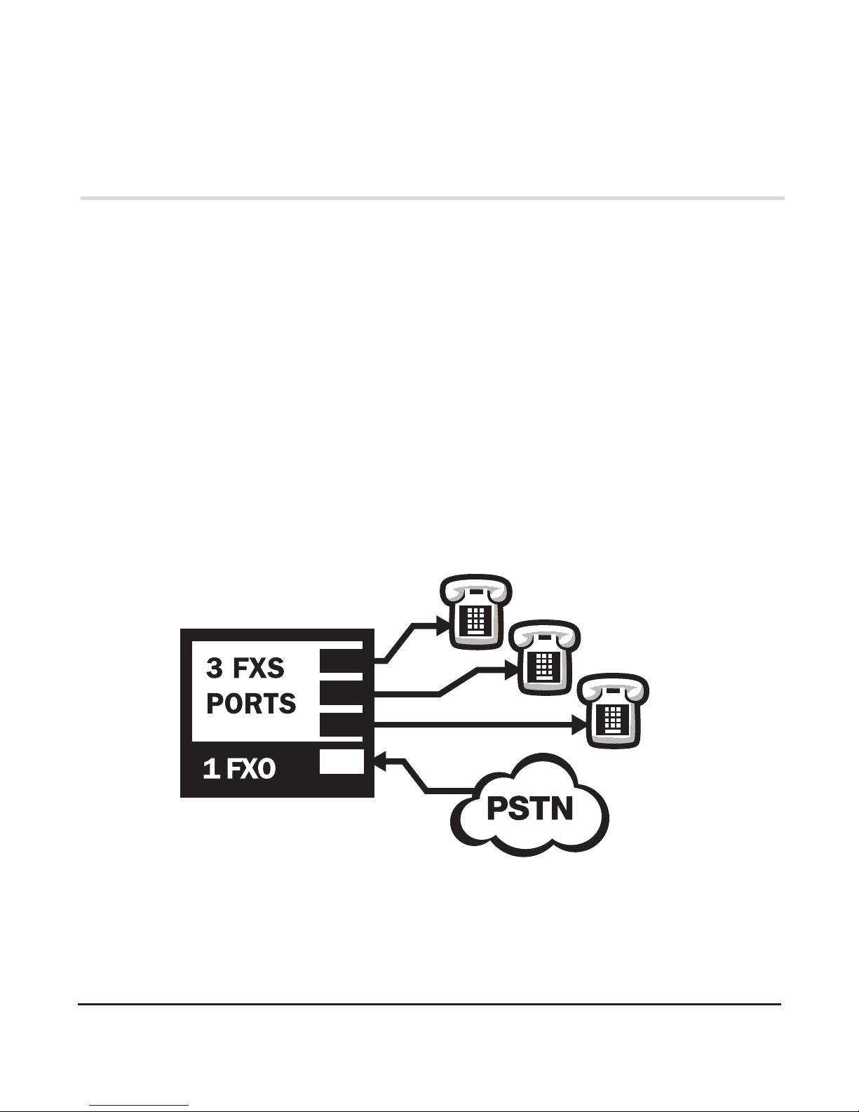
There are a variet y of applic ations where the Analog 410 Series cards
(TDM410 or the AEX410) can prove useful. An example is provided in
the followin g figure.
Figure 1: Sample Card Application
Digi u m , In c . Page 14
Page 15

Chapter 1: Overview
Echo-Cancellation
Users connecting the ir Analog 410 Series cards to the PSTN or other
devices are li kely to be placing calls that will result, at some point, in an
unbalance d 4-wire/2-wire hybrid. The result of this hybrid is the
reflection of a near -end echo to the calling party. Elimina tion of this echo
is the responsibility of echo cancel lation.
The Analog 410 Series cards, unless otherwise equipped, utilize Asterisk
to perform softwar e-based echo cancella tion. Asterisk maintains a
number of open source echo ca ncelers. Thes e open source echo cancelers
provide a moderate level of echo cancellation, but are not capable of
dealing with higher levels of, or more advanced, e choes.
Digium recommends that those use rs concerned about echo cancellation
purchase the VPMADT032 hardware echo canc ellation module . The
VPMADT032 may be combined with both the TDM410 and AEX410.
The VPMADT032 is de signed to h andle up to 128m s of ech o cance llati on
across all cha nnels and provides a G.168 echo cancellation solution.
Digium, Inc. Page 15
Page 16

Chapter 1: Overview
What is Asterisk®?
Asterisk is the world’s leading open source telephony engine and tool kit.
Offer ing flexibil ity unhe ard of in the world of proprietary
communications, Asterisk empowers developers and integrators to create
advanced communication solutions.. .for free. Asterisk is released as open
source under the GNU General Public License (GPL), and it is avail abl e
for download free of charge. Asterisk is the most popular open sourc e
software available, with the Asteris k Community being the top influence r
in VoIP.
Asterisk as a Switch (PBX)
Asterisk can be configured as the core of an IP or hybrid PBX, switchin g
calls, managing routes, enab ling features, and connecting call ers with the
outside world over IP, analog (POTS), and digita l (T1/E1) connections.
Asterisk runs on a wide variety of operating systems including Linux,
Mac OS X, OpenBSD, FreeBSD, and S un Solaris. It provides all of the
features you woul d expect f rom a PBX inclu ding many advanced f eatures
that are often associated with high end (and high cost) proprietary PBXs.
Asterisk 's architecture is designed for maximum flexibility and supports
Voice over IP in many protocols, and can interoperate with almost all
standards- based telephony equipment using relatively inexpensive
hardware.
Asterisk as a Gateway
It can also be built out as the hear t of a media gate way, bridging the
legacy PSTN to the expanding world of IP telephony. Asterisk’s modular
archite cture allows it to co nvert betwee n a wide range of c ommunicat ions
protocols and media codecs.
Digium, Inc. Page 16
Page 17

Chapter 1: Overview
Asterisk as a Feature/ Media Server
Need an IVR? Asterisk’s got you covered. How about a conference
bridge? Yep. It’s in there. What about an automated attendant? Asterisk
does that too. How about a replacement for your aging legacy voicemail
system? Can do. Unif ied messaging? No problem. Need a telephony
interfa ce for your web site? Ok.
Asterisk in the Call Center
Asterisk has been adopted by call centers around the world based on its
flexibility. Call ce nter and contact center developers have built complete
ACD systems based on Asterisk. Asterisk has also added new life to
existing c all center solutions by adding remote IP agent capabilities,
advanced skills-based routing, predictive and bulk dia ling, and more.
Asterisk in the Net work
Internet Telephony Servic e Providers (ITSPs), competitive local
excha nge carri er s (C LE CS ) and ev en fi rs t-tier incu m be n ts hav e
discovered the power of open source communications with Asterisk.
Feature se rvers, hosted services clusters, voicemail systems, pre-paid
calling solutions, all based on Asterisk have helped reduce costs and
enabled flexibility.
Asterisk Everywhere
Asterisk has become the basi s for thousands of communications
solution s. I f you need to communicate, Asterisk is your answer. For more
informati on on Asterisk, visit http://www.asterisk.org or http://
www.digium.com.
Digium, Inc. Page 17
Page 18

Chapter 2
Card Installation
This chapter provide s the following information:
Unpacking the Card on page 19
Shipm en t In spection on page 20
Module Identi fication on page 20
Port Iden ti fi cati on on page 21
Card Identification on page 24
FXS and FXO Connection on page 26
Slot Compatibility on page 26
Hardware Ins tallation on page 28
Software Installat ion on page 31
Installi ng Asterisk on page 35
Digi u m , In c . Pag e 18
Page 19

Cha p te r 2: C ar d In st a lla t io n
Unpacking the Card
When you unpa ck your card, carefully inspect it fo r any damage that may
have occurred in shipm ent. If damage is suspected, file a claim with the
carrier and contact the reseller from which the card was purchased, or
contact Digium Technical Support at 1.256.428.6161. Keep the original
shipping conta iner to use for future shipment or proof of damage during
shipment.
Note: Only qualified service personnel should install the card. Users
should not atte mpt to perform this function themselves. The installe r
must ensure that the equipment is permanently connected equipment,
pluggable type B or connecte d to a socke t-outlet t hat has bee n checked
to ensure that it is reliably earthed in accordance with the National
Electri ca l Cod e.
Thi s ca rd is in t ended fo r in s t a ll a tion in a Rest ricte d Access
Location (RAL) only.
Digium, Inc. Page 19
Page 20

Cha p te r 2: C ar d In st a lla t io n
Shipment Inspection
The following it ems are included in shipment of an Analog 410 Series
card:
Analog 410 S eries card (TDM410 or AEX410)
FXO and/or F XS module(s) (depending on c onfiguration)
Module Identification
The Analog 410 Series card ships with FXO and/or FXS modules in
place. These are ide ntified by their color. Take a moment to identify
which modules were ship ped with your card.
FXO (Foreign Exchange Office) modules a re Red
FXS (Foreign Exchange S tation) modules are Green
See Figure 2 on page 22 for an example of the TDM410 card shown with
two of each single module.
See Figure 3 on page 23 for an example of the AEX410 card shown with
two of each single module.
The Analog 410 Series cards may als o be combined with Digium’s
hardware- based echo canceler, model VPMADT032. See Figure 2 on
page 22 for an example of the TDM410 card shown with one of each
analog module and the echo can cella tion module.
Digium, Inc. Page 20
Page 21

Cha p te r 2: C ar d In st a lla t io n
Port Identification
Each card consists of four RJ11 ports located on the PCI bracket. Each
port cor relat es to a sing le mo dul e (con t ain in g eit her FX O or FX S
modules). The ports are numbered in sequence from one to four. The top
port is Port 1 and the bottom port is Port 4. See Figure 2 on page 22 for
appropria te identification of these ports. The port identification is the
same for all cards in this series.
A status LED accompanies each port on the PCI bracket. Illumination of
this LED indicates tha t a module is installed for the port located directly
below it on the PCI bracket.
It is im portant to identify the type and location of your Analog 410 Series
modules. You will need this information during the configuration of
Asterisk.
The port s availa ble f or use on the Analog 410 Se ries c ards are conti nuous.
The cards can accept 4 sing le mo dules , for a total of 4 ports . Th e sing le
module po rts ar e ide ntifi ed on the c ard a nd their c orr esponding RJ1 1 ports
are identified below. The RJ11 port availa ble for use will be the port
correspo nding to the location of the module on the card. The following
ports corr espond to the single module ports as shown in Fig ure 2 on pa ge
22.
RJ11 Port 1 is used by Single Module Port 1
RJ11 Port 2 is used by Single Module Port 2
RJ11 Port 3 is used by Single Module Port 3
RJ11 Port 4 is used by Single Module Port 4
Digium, Inc. Page 21
Page 22

Cha p te r 2: C ar d In st a lla t io n
Single
Modules
Power
Supply
Connection
1
2
3
4
1
2
3
4
VPMADT032 Echo
Cancellation Module
Status
LED
Figure 2: TDM410 Card with Four Single Modules
Digium, Inc. Page 22
Page 23

Cha p te r 2: C ar d In st a lla t io n
Single
Modules
1
2
3
4
1
2
3
4
Power
Supply
Connection
VPMADT032 Echo
Cancellation Mo dule
Status
LED
Figure 3: AEX410 Card with Four Single Modules
Digium, Inc. Page 23
Page 24

Cha p te r 2: C ar d In st a lla t io n
Card Identification
There are multiple configurations in which an Analog 410 Series card
may be purchased. Each configu ration cons ists of a combina tion of singl e
modules and may also include the VPMADT032 echo cancellation
module. See Ta ble 1 on page 24 for a list of the most common TDM410
configurations. See Table 2 on page 25 for a list of the most common
AEX410 configu rations. The list s are not comple te, bu t rather a n exa mple
of the configurations available.
It is e asiest t o identify your card by understanding the naming scheme for
each card. The first digit is the maximum port count of the card. The
second digit is the number of FXS (station) modules present on the card.
The thir d digit is the number of FXO (of f ice) module s pre sent on the c ard.
Table 1: Example TDM410 Card Configurations
FXO/FXS
Car d ID
Port s
TDM401B 1 FXO module
TDM404B 4 FXO modules
TDM422B 2 FXS and 2 FXO modules
TDM440B 4 FXS modules
Digium, Inc. Page 24
Page 25

Table 2: Example AEX410 Card Configurations
FXO/FXS
Car d ID
Port s
AEX401B 1 FXO module
AEX404B 4 FXO modules
AEX422B 2 FXS and 2 FXO modules
AEX440B 4 FXS modules
Cha p te r 2: C ar d In st a lla t io n
Digium, Inc. Page 25
Page 26

Cha p te r 2: C ar d In st a lla t io n
FXS and FXO Connection
The Analog 410 Series cards pr ovide four RJ11 connectors for access to
the FXS and/ or FXO modules i nsta lled i n the a vailable slots. The dia gra m
in Table A-1 on page 56 provides the pinout fo r this connector.
Caution.
Only qualified service perso nnel should co ntinue with
hardware in st allation and configur ation of the Analog 410
Series card. Users should not attempt to perform these
functions themselves.
Slot C ompatibility
Check the type of card you received to be sure it is compatible with your
PCI slot. To determine which slot you have, identif y it by comparing it to
those shown in Figure 4 on page 27.
Slot Number:
0: AGP Pro Slot
1: 64-bit 5.0 volt PCI Slot
2: 64-bit 3.3 volt PCI Slot
3: 32-bit 5.0 volt PCI Slot
4: PCI Expr ess Slot
Digium, Inc. Page 26
Page 27

Cha p te r 2: C ar d In st a lla t io n
0
1
2
3
4
Slots
Figure 4: Motherboard Slots
The TDM410 card is a 32-bit 33MHz card keyed for universal 3.3 volt or
5.0 volt operation and works in any PCI 2.2 (or greater) compliant slot.
This means tha t in the motherboard shown in Figur e 4, the TDM410 card
will fit into Slots 1, 2, or 3 (PCI slots), but will not fi t in t o Sl ot 0 ( A GP
slot) or Slot 4 (PCI Express slot) .
The AEX410 card is a PCI Express card. Slot 4, illustrated above, is a 1
lane (X1) PCI Express compliant slot. The AEX410 will work in any PCI
Express compli ant slot, including la ne lengths X4, X8, and X16. This
means that in the motherb oard shown in Figure 4, the AEX410 will only
fit into Slot 4. The AEX410 can not be used in Slots 0 through 3.
Digium, Inc. Page 27
Page 28

Cha p te r 2: C ar d In st a lla t io n
Hardware Installation
1. Now that you are acquainted with your card, power down your com-
puter and unplug it from its power source.
2. Att ach a static strap to your wrist and open the case .
3. Remove the bracke t place holder and insert the card into a PCI
(TDM410) or PCI Express (AEX410) slot. See Figure 5.
Figure 5: Insert the Card
4. If your card has any FXS modules, you will also need to connect the
power cable from your computer’s power supply to the back of the
card. Insert a four-pin 12 volt connector (disk drive power supply
cable, e.g. hard drive) into the white plastic connector on the rear of
th e card. See Figure 6.
Digium, Inc. Page 28
Page 29

Cha p te r 2: C ar d In st a lla t io n
Figure 6: Connect Power for FXS Modules
Many modern PCs and servers do not have either spar e or any 12V power
connector s. I f you have FXS modules on your card and your computer
does not have power cables available, then powe r must be provided to the
Analog 410 S eries card by an a lter nate mea ns. Digi um prov ides a solutio n
to this proble m with the optional PWR2400B (available separately). This
card is essentia lly a PCI bracket assembly that ta kes power from an
external DC power s upply and route s it to two 15 " powe r cabl es insi de the
computer. You must have an available bracket slot to use the PWR2400B
(either PC I, PC I E xpr es s or AGP).
A strap on the PWR2400B card allows the two power cables to take
power from the same DC supply. The PWR2400B comes with one power
supply capable of supporting up to 24 FXS ports each, driving heavy
loads of up to 5REN. If more than 24 FXS por ts with heavy loads a re
connected to the PWR2400B, then a sec ond Digium power Suppl y shoul d
be purchased. The shorti ng strap on the PWR2400B should be removed i f
a second power supply is use d.
Digium, Inc. Page 29
Page 30
Cha p te r 2: C ar d In st a lla t io n
The PWR2400B does not connect to any bus inside the computer. It may
be used wh ere v er the re is an available PCI-s ize bracket such as a PCI,
PCI Express, or AGP slot.
Note: The PWR2400B is not intended to supply power to any other
device, it is intended only to be used with UL Listed Digium analog
cards.
5. Repl ace the cover to your computer.
Electrical Shock.
To reduce the risk of injury, damage to the unit or your
equipment, do not atte mpt to apply power to the unit while the
case i s open.Pers onal injury or damage to t he unit could occur
if the modules are touched while powered is applied.
6. Plug a ll outside phone lines to the FXO (red) ports a nd connect all
phones to the FXS (green) por ts as needed using a patch panel or
punch block. See Table A-1 on page 56 for the pin assignments.
Caution.
This unit must be connected to the Telecommunications
Networ k in your country us ing an approved line cord, e.g.: for
Australia use only line cor ds complying with ACA Technical
Standard TS008.
Caution.
Only conne ct regulatory equipment (approv ed for use in your
specific country) to the telecommunications network voltage
circuit ports.
Digium, Inc. Page 30
Page 31

Cha p te r 2: C ar d In st a lla t io n
Soft w a r e In s t al la tion
Digium hardware req uires drivers and librar ies that are not integrated
with the Linux kernel . Digium hardware is only support ed under Linux.
Digium recommends CentOS , Debian, Red Hat, and Ubuntu distr ibut ions
of Linux. However, many other distributio ns are supp orted by Digium
Technical Support.
Digium’s software, including drivers and applic ation software, may be
obtained fr om Digium’s download server at:
http://downloads.digium .com
For an introduction to Aste risk, Digium’s telephony software, including
additiona l information on its configuration, set up, a nd features, pleas e
refer to:
http://www.asterisk.org
For the latest inf ormation on setting up and configuring DAHDI drivers
for your Digium hardware produ ct, ple ase refer to t he latest relea se of this
manual which is avail able from the product-specific documentation
section at:
http://www.digium.com
To install your Analog 410 Series car d, you will need:
Linux 2.6 kernel headers
Development li braries and headers for ncur ses
Development li braries and headers for zlib an d openssl
Development li braries and headers for newt
GCC and standard software build tools
It is recommended that you use the most recent version of the Asterisk,
DAHDI, and libpri software for the best results. If you have previously
Digium, Inc. Page 31
Page 32

Cha p te r 2: C ar d In st a lla t io n
installe d any of these, Digium recommends that you upgr ade to the latest
“-current” version of each.
Note: If you are using the 1.4.x series of Asterisk, you will need
Asterisk 1.4.22 or newer.
1. Afte r the machine has booted to Linux, log in and execute the follow-
ing command to list the devices detected by the PCI bus:
# lspci -n
Confirm that the out put from lspci lists a device with Digi um’s PCI
vendor ID which is “d161” . The screen output should be similar to the
following:
0000:01:00.0 0200:d161:<card identifier>
Note: The output from lspci may or may not state “Unknown
device”. If it does, this does not indicate a proble m.
In the PCI device listing shown a bove, <card identifier> will be
populated with one of the identifiers listed in the table below.
Digium, Inc. Page 32
Page 33

Cha p te r 2: C ar d In st a lla t io n
Table 3: Card Identifiers
Model Identifier
TDM410 8005
AEX410 8006
A Digium Analog 410 Series (TDM410/AEX410 ) card identifier
should be liste d. I f a matching card identifier is not listed, then your
machine is not PCI 2.2 (or higher) or PCI Express compatible, and the
card will not work with your mother board.
2. Download the latest DAHDI drivers with tools. DAHDI is available
for dow nload fro m :
http://downloads.digium .com/pub/telephony/dahdi-linux-complete
# wget http://downloads.digium.com/pub/telephony/
dahdi-linux-complete/dahdi-linux-completecurrent.tar.gz
Digium, Inc. Page 33
Page 34

Cha p te r 2: C ar d In st a lla t io n
3. Expan d the dow n lo aded fi le, co m pile its co ntent s , and ins ta ll the
drivers a nd tools. Substitute the version of DAHDI for the X.X.X in
the command lines below.
# tar -zxvf dahdi-linux-complete-current.tar.gz
# cd dahdi-linux-complete-X.X.X+X.X.X
# make
# make install
# make config
Note: Executing ‘make config’ will install an init script and symlinks
which will allow you to star t and stop DAHDI as a service.
Digium, Inc. Page 34
Page 35

Cha p te r 2: C ar d In st a lla t io n
Installi ng Asterisk
If you wish to use Asterisk with your new hardware, you can follow the
instruc tions below.
1. Download the late st release version of Asteri sk, eith er 1.4.22 ( or later)
or 1.6.0.1 (or later). Substitute the version of Asterisk for the X.X in
the command below. Asterisk is availa ble for download from:
http://downloads.digium .com/pub/telephony/aste risk
# wget http://downloads.digium.com/pub/telephony/
asterisk/asterisk-X.X-current.tar.gz
2. Expan d the dow n lo aded fi le, co m pile its co ntent s , and ins ta ll the
application. Substitute the version of Asterisk for the the X.X and
X.X.X in the command lines below.
# tar -zxvf asterisk-X.X-current.tar.gz
# cd asterisk-X.X.X/
# ./configure
# make menuselect
# make
# make install
Digium, Inc. Page 35
Page 36

Cha p te r 2: C ar d In st a lla t io n
3. If thi s is t he first Aste risk i nstall ation o n th is s ystem, yo u sho uld install
the sample confi guration files. To do this, run:
# make samples
Note: Running this command will ove rwrite, after making a backup
copy, any older Asterisk configur ation files that you have in the /etc/
asterisk directory.
If your installation has failed, it may be because you are missing one
or more of the build dependenc ies, the kernel header s, or the
development tools. Please contact your reseller where the card was
purchased , or call Digium Technic a l Support at 1.256.428.6161 for
assistance.
Complete instruc tions for installing Asterisk are available at
www.asterisk.org
.
Digium, Inc. Page 36
Page 37

Chapter 3
Configuration
The Analog 410 Se ries car ds have a va riety of configurati on opti ons. This
chapter provide s sample configurations to demonstrate customizing the
Asterisk software to meet your individual needs. Each section expla ins
basic option s as examples. Once you have familiarized yourself with the
samples, you can edit the configuration files to meet your specific needs.
Digi u m , In c . Pag e 37
Page 38

Driver Confi guration
Chapter 3: Configuration
1. Begin by opening the system.conf file from the
/etc/dahdi directory.
2. Specify th e two letter c ountry code for your loa dzone and def aultzone .
This will prelo ad tone zone data and specify a default tone zone for
your interf aces.
The following is a typical setup for a telco in the US:
loadzone = us
defaultzone = us
Digium, Inc. Page 38
Page 39

Chapter 3: Configuration
3. Specify the channel definitions. The format is:
<device> = <channel list>
A list of valid devices a re spe cified in the sample system. conf file.
If your card has any red FXO modules, add the following to
system.conf:
fxsks =
fxsks uses kewlstart si gnalling, which is loopstart signalling with disconnect
supervision. For example, a TDM404E card would be configure d as the
following:
fxsks = 1-4
OR
fxsks = 1,2,3,4
You should have identified the type of Analog 410 Series card when you
received it. If you are not sure, refer to
for assistance.
Mod ule I den ti fica ti on on page 23
Note: The Analog 410 Series cards do not support Ground Start
signaling.
Digium, Inc. Page 39
Page 40

Chapter 3: Configuration
4. If your card has any green FXS modules, add the following:
fxoks =
fxoks uses kewlsta rt signalling, whic h is loopstart signalling with
disconnect supe rvision. For example , a TDM440E card would be
configured as the following:
fxoks = 1-4
OR
fxoks = 1,2,3,4
5. An example TDM422E card configuration would be:
fxoks = 1-2
fxsks = 3-4
OR
fxoks = 1,2
fxsks = 3,4
6. DAHDI uses modular echo cancellers tha t are configured per channel.
The echo cancelle rs are compiled and installed as part of the dahdilinux package . You can specify the echo canceller to be used for each
channel. The default behavior is for there to be no echo canceller on
any channel. So, it is very important that you specify one in the
Digium, Inc. Page 40
Page 41

Chapter 3: Configuration
system.conf file if you do not have hardware echo cancellers and need
echo canc el la tion . Th e fo rma t is:
echocanceller = <echocanceller name>,<channel(s)>
A list of valid echo cance lle rs are specified in the sample system.conf
file.
The following is a typical setup using software-based echo
cancellation:
echocanceller = mg2,1-4
7. Load DAHDI dr ivers into the kernel using the modprobe utility. The
appropria te driver for the Analog 410 Series car ds is wctdm24xxp.
Users should use the following modprobe command:
# modprobe wctdm24xxp
# dahdi_cfg -vv
# dmesg
Note: The Analog 410 Series cards use the sam e driver as the
TDM2400.
Digium, Inc. Page 41
Page 42

Chapter 3: Configuration
Figure 7: Example dmesg Screen Shot
Note: Output as shown above may vary dependin g on the Analog 410
Series card you use.
Digium, Inc. Page 42
Page 43

Chapter 3: Configuration
Configuring Card Feat ures
You will need to modify t he chan _dahdi.conf file which is located in the
/etc/asterisk directory in order to configure the essential features of your
card. This file is the configuration layer between DAHDI and Asterisk.
The following is a sample configuration for a TDM422E c ard. You can
place this at the bottom of your
chan_dahdi.conf file.
;General options
usecallerid = yes
hidecallerid = no
callwaiting = yes
threewaycalling = yes
transfer = yes
echocancel = yes
echocancelwhenbridged = yes
rxgain = 0.0
txgain = 0.0
;FXS Modules
group = 1
signalling = fxo_ks
context = Internal
channel = 1-2
;FXO Modules
group = 2
echocancel = yes
signalling = fxs_ks
context = Incoming
Digium, Inc. Page 43
Page 44

Chapter 3: Configuration
channel = 3-4
Users of Digium' s har dware ec ho ca ncellat ion module, t he VPMADT032,
should set the echoca ncel option to "yes." The module will automatically
configure itself to run a t full capacity, 1024 taps ( 128ms), on each
channel.
Users without the VP MADT032 using open source echo cancelers
included wit h DAHDI should configure echocancel to the values 128
(16ms) or 256 (32ms). Setting "yes" will de fault the option to 128 (16ms).
Users who have not purchased an Analog 410 Series card with the
hardware echo canc ellation module are encoura ged to take advantage of
Digium's High Performance Echo Canceler softwa re. This commercially
licensed sof tware, which is made available at no charge to in-warranty
Digium analog inte rface card customers, provide toll quali ty echo
cancellation, performed on the host CPU, at up to 1024 taps (128ms) per
channel. For further details about HPEC, ple ase refer to the Digium
website here:
http://www.digium.com/en/products/software/hpec.php
When HPEC is enabled, users may set the value of the echocancel
parameter to any of the following values:
128 - 16ms
256 - 32ms
512 - 64ms
1024 - 128m s
Note: Higher values will result in dramatically increased CPU
consumption . In order to optimize system performance, users are
Digium, Inc. Page 44
Page 45

Chapter 3: Configuration
encouraged to cho ose the mini mum value requir ed to cancel their
echo.
Voicemail
Open
[default]
1234 => 4242,Mark Spencer,root@localhost
voicemai l.con f and find the following line at the bottom:
In this example, 1234 is the mailbox number, 4242 is the password, Mark
Spencer
is the person’s name, and root@l ocalhost is h is em ai l addres s .
You can add extensions by adding the following:
1000 => 1234,Moose Member,moose@digium.com
2000 => 1234,Bill Savage,bsavage@digium.com
Digium, Inc. Page 45
Page 46

Dial Plan
Chapter 3: Configuration
Open
extensions.conf, which contains a large, complex sa mple dial
plan. In this step, you will configure a basic dial plan to enable you to
send and receive calls. Go to the bottom of the file and add the followi ng
lines:
[Internal]
exten => 1000,1,Dial(DAHDI/1,20,rt)
exten => 1000,2,Voicemail(1000,u)
exten => 1000,102,Voicemail(1000,b)
exten => 2000,1,Dial(DAHDI/2,20,rt)
exten => 2000,2,Voicemail(2000,u)
exten => 2000,102,Voicemail(2000,b)
exten => 8500,1,VoiceMailMain
exten => 8501,1,MusicOnHold
exten => _9.,1,Dial(DAHDI/g2/www${EXTEN:1})
exten => _9.,2,Congestion
[Incoming]
exten => s,1,Answer
exten => s,2,Dial(DAHDI/g1,20,rt)
exten => s,3,Voicemail(1000,u)
exten => s,103,Voicemail(1000,b)
In this example there are two internal extensions (1000 and 2000), a
number to check voicemai l (8500), a number to listen to music-on- hold,
Digium, Inc. Page 46
Page 47

Chapter 3: Configuration
(8501), and a prefix to dial to get an outside line (9). It is configured to
accept incomi ng calls over the FXO, rings phones 1 and 2, and route to
voicemail box 1000.
Testing Your Configuration
1. Start Asterisk by typing:
asterisk
2. Conne ct to Asterisk and view the output by typing:
asterisk -vvvvr
3. Dial tone should be present on phones connected to the FXS ports.
Test your configuration by placing an outgoing call, pla cing a call
from extension 1 to 2, or receiving an incoming call. Successful
completion of these tasks indicates your configuration is working
properly.
Digium, Inc. Page 47
Page 48

Chapter 3: Configuration
Figure 8: Sample Application
Note: More detailed information is provided at the Asterisk website
(www.asterisk.org), as well as the Digium Knowledge Base
(kb.digium.com). You may also obtain assistance by contacting
Digium Technical Support at 1.256.428. 6161 or visitin g the website at
www.digium.com
.
Digium, Inc. Page 48
Page 49

Chapter 4
FXS and FXO Explained
Identification
There are multiple st andar d configur ations in which a n Analog 4 10 Serie s
card may be purchased. Each configuration consists of one to four FXS
and/or FXO modules. These modules are identified by their color.
FXS - Foreign Exchange Stati on (Green Modules)
FXO - Foreign Exchange Off ice (Red Modules)
This chapter provide s an in-depth review of the two module types and
their uses within your Asterisk server.
Note: Only qualified service personnel should install the card. Users
should not atte mpt to perform this function themselves.
FXS Module
The FXS module allows an Analog 410 Series card to initiate and send
ringing voltage to an FXO de vice such as a n analog telephone.
FXO Module
The FXO module allows a n Analog 410 S eries card to terminate analog
telephone line s (POTS). Because of the modular desi gn, you can activate
additiona l ports at any time with more FXS or FXO daughter cards. The
FXO module passes all the call features any standard analog telephone
line will support. The phone receiving the call is the last FXO device in
the chain. When it receive s voltage from an FXS device, the phone rings.
Digi u m , In c . Pag e 49
Page 50

Chapter 4: FXS and FXO Explained
Using Your Analog 410 Series Card
Connect the outside line to an F XO port on you r Aster isk server to rece ive
voltage from the outside lines.
Connect the phones to FXS por ts on your Asterisk ser ver. When the FXO
module in your Asterisk Ser ver receives the volta ge, it will then generate
voltage usin g the FXS module and send it to your analog phone .
Digium, Inc. Page 50
Page 51

Chapter 5
Troubleshooting
This cha pter provides fr equently asked questio ns and possible resolutions
as identified by Digium Technical Support. Multiple resources are
available to obt ai n more information a bout Aste risk and Digi um products.
Please visi t both www.digium.com and www.asterisk.org for more
information.
Digi u m , In c . Pag e 51
Page 52

Chapter 5: Troubleshoot ing
The FXO module never seems to hang-up the line. How do I set it to
hang-up?
busydetect = yes and busycou nt = 10 in the chan_dahdi.co nf for
Set
your channels . This will cause the line to hang-up by lis te ning for a
consecutive number of busy tones. Upon editing
chan_dahdi.conf, you
will need to restar t Asterisk.
I have echo problems on my FXO modules and I've tried the different
echo cancellation algorithms in dahdi_config.h, tried tweaking the
gains, and still nothing works. What can I do?
Run the fxotune ut ility with the -i option (fxotune -i 4) . It should discover
which DAHDI channels are FXO modules and tune them accordingly. Be
warned however, it takes a significant amount of time for each module to
tune. A conservative estimate would be somewhere around 2-3 minutes
for each module. You only have to tune the channels once for each line.
The fxotune utility will store the calibration se ttings in /etc/fxotune.conf.
You will need to configure your system to run fxotune with the -s flag
(fxotune -s ) during the Linux boot sequence in order to initialize the
previously discovered values which are stored in fxotune.conf. A
recommendation is to put ‘f xotune -s’ in your distrib ution’s startup scripts
at some point after the DAHDI module loads and bef ore Asterisk
executes.
Note: The digit after the -i option is the digit that will break dialtone
on the line.
Digium, Inc. Page 52
Page 53

Chapter 5: Troubleshoot ing
There is a slight echo. How can I adjust the sound quality?
There are several options available to correct this. Each involves editing
chan_dah di .co nf file. Be sure to restart Asterisk upon completion.
the
1. Adjust echocancel = yes to one of the following valu es: 32, 64, 128,
or 256
2. You can also s et
3. You can also ad j ust the
recommended to shift between
.
echotra i n in g = ye s.
rxgain and the txgain, although it is only
-5 and 5.
How can I enable more features?
To view all of the options available to add to your dial pla n, type the
following commands f rom within Asterisk:
*CLI> core show applications
*CLI> core show functions
Digium also off ers services to help configure and add features you might
need. Contact Digium Technical Support at 1.877.DIGIUM. 1
(1.877.344.4861) for more information.
Digium, Inc. Page 53
Page 54

Chapter 5: Troubleshoot ing
Common Fixes
1. Check to see if t he X Window System (e.g. X.Or g Server) is running
by entering the following:
# ps aux | grep X
If the X Window System is running, stop the application since it may
cause a conflict with Asterisk.
2. Check to see if your PATA IDE hard drives are running with DMA
levels set. Advance user can perform an
hdparm on your hard drive
interface.
Use hdparm wi th cautio n as the man pa ge st ates tha t h ar d drive
corruption can occur when using incorrect settings. Plea se
re view t he man page for hdp arm and mak e sur e you unde rstand
the risks before using thi s tool.
Check the current mode using this comm and:
hdparm -vi /dev/[IDE Device]
Use this command to set the drives into UDMA2 mode:
hdparm -d 1 -X udma2 -c 3 /dev/[IDE Device]
If you are still having problems, contact your reseller from which the
card was purc hased, or Digium Technical Suppor t at 1. 877.DI GIUM.1
(1.877.344.4861).
Digium, Inc. Page 54
Page 55

Chapter 5: Troubleshoot ing
Where can I find answers to additional questions?
There are several places to inquire for more information about Asterisk
Digium products:
1. Digium Technical Support (+1. 256.428.6161), or Toll Free in the U.S.
(1.877.3 44.4861), is avail abl e 7am-8pm Central Time (GMT -6),
Monday - Friday.
2. Asterisk users mailing list (asterisk.org/lists.digium.com
3. IRC chan nel
#asterisk on (irc.freenode.net).
).
Subscription Services Program
Digium is dedicat ed to supporting your Asterisk system by offering full
technical support through our Subscription Services Program. Through
this program, you can be at ease knowing tha t your busine ss will always
have access to the Asteris k experts. P ricing on Subscri ption Service s may
be obtained from your nearest reseller or you may call Digium Sales for
referral to your nearest reseller at +1.256.428.6 000 or e-mail
sales@digium.com.
Digium, Inc. Page 55
Page 56

Appendix A
Pin 1
Pin 6
Pin Assignments
All four ports on the Analog 410 S eries card’s bracket are 6-pin RJ11
ports. The pin assignments are identified in Table A-1.
Table A-1: RJ11 Telco Port Connector
Pin Description
1 Not used
2 Not used
3Tip
4Ring
5 Not used
6 Not used
Digi u m , In c . Pag e 56
Page 57

Appendix B
Specifications
This appendix provides specifications, required environmental
conditions, and maximum power consumption for the Analog 410
Series cards.
Physical (All Cards) .
Size: 6.48” × 4.2” × 0.68” (16.46 x 10.67 x 1.72 cm)
PCB size, does not include the PCI br acket.
Check your model carefully to be sure it will accept
this PCI card.
Weight: 3.5 oz (99.22 gm) with no modules loaded
Each single module adds 0.4 oz (11.34 gm)
VPMADT032 adds 0.63 oz (17.86 gm)
Interfaces.
Local Loop Access: Industry standard 6-pin RJ-1 1.
(TDM410) - PCI Bus: 3.3V or 5V bus slot, half-length full-height PCI
card, 33MHz minimum bus speed, compliant with PCI 2. 2 or greater.
Additional Power : four-pin 12V connector for FXS power supply
(requir ed only if FXS modules are installed)
(AEX410) - PCI-E X1, compliant with PCI-E X1 1.0 or greater.
Digi u m , In c . Pag e 57
Page 58

Appendix B: Specifications
Environment.
Temperature: 0 to 50° C (32 to 122° F) operation
-20 to 65° C (-4 to 149° F) storage
Humidity: 10 to 90% non-condensing
Note: Operating temperature is limited to 0 to 40° C (32 to 104°F)
when used with optional PWR2400B Power Bracket
Hardw are an d So ftwa re R equ i rements.
500-Mhz Pentium III or better
64MB RAM
Available PCI Slot or PCI-Express Slot (as described previously)
Power C ons u m pti on.
The following table lists the power consumption for both the TDM410
card (and its permut ations) and the AEX410 (and its permutations).
Note: 3.3 and 5 vo lt po wer is taken f rom th e PCI slot. 12 volt power is
taken only from the four-pin hard disk drive connector or optional
PWR2400B.
Digium, Inc . Page 58
Page 59

Appendix B: Specifications
Table B-2: Maximum Power Consumption
Model Power
3.3V All TDM models 4.25W
5.0V All TDM models 0.1W
5.0V All AEX models 0W
12V AEX/TDM404E 0W
AEX/TDM414E into 1REN 0W
AEX/TDM411E into 3REN 2.5W
AEX/TDM422E into 3REN 3.5W
AEX/TDM440E into 3REN 5W
Digium, Inc . Page 59
Page 60

Appendix C
Glossary and Acrony ms
ANSI American National St andards Institute
An orga nization which proposes and establishes standards for
internationa l communications.
asynchronous
Not synchronize d; not timed to an outside clock source. Tra nsmission is
controll ed by start bits at the beginning and stop bits at the end of each
characte r. Asynchronous communica tions are often found in internet
access and remote office applications.
attenuation
The dissipat ion of a transmitted signal’s power as it travels over a wire.
bandwidth
The capacity to carry traffic. Higher bandwidth indicates the ability to
transfe r more data in a given tim e period.
bit
The smallest element of information in a digital system. A bit can be
either a zero or a one.
bps bits per second
A measurement of trans mission speed across a data connection.
Digi u m , In c . Pa g e 60
Page 61

Appendix C: Glossary and Acronyms
broadband
Broadband tra nsmission shares the bandwidth of a particular medium
(copper or fiber optic) to integrate multiple signals. The channels take up
diff erent frequencies on the cable, integr ating voice, data, and video ove r
one line.
channel
A generic term for an indivi dual data stream. Servic e providers can use
multiplexing techniques to tr ansmit multiple channels over a common
medium.
Cat5
Category of Perfor mance for wiring and cabling. Cat 5 cabling support
applications up to 100 MHz.
Cat5E
Category of Perfor mance for wiring and cabling. Cate gory 5 Enhanced
wiring suppor ts signal rates up to 100 MHz but adheres to stricter quality
specifications.
CLEC competitive local exchange carrier
A term for telephone companies establish ed aft er the
Telecommunications Ac t of 1996 deregulated the LECs. CLECs compete
with ILE Cs to o ffer loca l serv ice. See al so LEC and ILEC.
Digium, Inc. Page 61
Page 62

Appendix C: Glossary and Acronyms
CO central office
The CO houses local switching equipment. All loc al access lines in a
particular geographic area terminate at this facility (which is usually
owned and operated by an ILEC).
CPE customer premises equipment
Terminal equipment which is connected to the telecommunications
network and which resid es within the home or office of the customer . This
includes telephones, modems, te rminals, routers, and television set-top
boxes.
DAHDI Digium Asterisk Hardware Device Interface
A telephony project dedicated to implementing a reasonable and
affor dable c ompute r tele phony pl at form in to t he world mar ketplac e. Al so,
the collect ive name for the Digium-provided drivers for Digium
telephony interface products.
DS0 Digital Signal, Level 0
A voice grade channel of 64 Kbps. The worldwi de standa rd speed for
digitizing voice conversation using PCM (Pulse C ode Modulation).
DS1 Digital Signal, Level 1
1.544 Mbps in North America (T1) and Japan (J1) -up to 24 voice
channels (DS0s) , 2.048 Mbps in Europe (E1) - up to 32 voice channels
(DS0s). DS1/T1/E1 lines are part of the PSTN.
Digium, Inc. Page 62
Page 63

Appendix C: Glossary and Acronyms
DS3 Digital Signal, Level 3
T3 in North America and Japan, E3 in Europe. Up to 672 voice channe ls
(DS0s). DS3/T3/E3 lines are not part of the PSTN.
DTMF Dual Tone Multi-Frequency
Push-butt on or touch tone dialing.
E1
The European equiva lent of North American T1, transmi ts data at 2.048
Mbps, up to 32 voice channels (DS0s) .
E3
The European equivalent of North American T3, transmits dat a at 34.368
Mbps, up to 512 voice channels (DS0s). Equivalent to 16 E1 lines.
EMI Electromagnetic Interference
Unwanted electrical noise present on a power line
full dupl e x
Data transmission in two directions simultaneously.
FXO Fore ign Exchan ge Office
Receives the ringing voltage from an FXS device. Outside lines are
connected to the FXO port on your 800 Series card.
Digium, Inc. Page 63
Page 64

Appendix C: Glossary and Acronyms
FXS Fore ign Exchan ge Station
Initiat es and se nds ringin g vol tage. P hones ar e conne cted to the FXS ports
on the 800 Series card.
G.711
A recommendation by the Telecommunication Standa rdization Sector
(ITU-T) for an algorithm designed to trans mit and receive mulaw PCM
voice and A-law at a digital bit r ate of 64 Kbps. This algorithm is used fo r
digital telephone sets on digital PBX.
G.723.1
A recommendation by the Telecommunication Standa rdization Sector
(ITU-T) for an algorithm designed to trans mit and receive audio over
telephone line s at 6.3 Kbps or 5.3 Kbps.
G.729a
A recommendation by the Telecommunication Standa rdization Sector
(ITU-T) for an algorithm designed to trans mit and receive audio over
telephone line s at 8 Kbps.
H.323
A recommendation by the Telecommunication Standa rdization Sector
(ITU-T) for multim edia communications over packet-based networks.
IAX Inter- A steri sk eXchange
The native VoIP protocol used by Asterisk. It is an IETF standard used to
enable VoIP connect ions between Asterisk servers, and between serv ers
and clients tha t also use the IAX protocol.
Digium, Inc. Page 64
Page 65

Appendix C: Glossary and Acronyms
iLBC internet Low Bitrate Codec
A free speech codec used for voice over IP. It is designed for narrow band
speech with a payload bitrate of 13.33 kbps (frame length = 30ms) and
15.2 kbps (frame length = 20 ms).
ILEC incumbent local exchange carrier
The LECs that we re the origi nal carrie rs in the mar ket pr ior to th e entry of
competition a nd therefore have the dominant position in the market.
interface
A point of contact betwe en two systems, networks, or devices.
ISO International Standards Organization
LED light-emitting diode
Linux
A robust, feature-packed open source operating system based on Unix
that remains fre ely available on the interne t. It boasts dependa bility and
offers a wide range of compatibility with hardware and software. Asterisk
is supported exclusively on Linux.
loopback
A state in whi ch the transmit signal is reversed back as the receive s ignal,
typically by a far end ne twork element.
Digium, Inc. Page 65
Page 66

Appendix C: Glossary and Acronyms
MGCP Media Gateway Control Protocol
multiplexing
T ransmitting mul tiple signals over a single line or channel. FDM
(frequenc y division multiplexing) and TDM (time division multiplexing)
are the two most c ommon methods. FDM separates signals by dividing
the data onto different carrier frequencies, and TDM separates signals by
interlea ving bits one after the other.
MUX multiplexer
A device which transmits multiple signal s over a single communications
line or channel. Se e multiplexing.
PBX private branch exchange
A smaller versio n of a phone company’s large centr a l switching of fice.
Example: Aste risk.
PCI peripheral component interconnect
A standard bus used in most computers to c onnect peripheral devices.
POP point of presence
The physical connection point between a network and a telephone
network. A POP is usually a network node serving as the equivalent of a
CO to a network service provide r or an interexchange carr ier.
POTS plain old telephone service
The public switche d telephone network (PSTN) is the network of the
world's public circuit-switched telephone networks. Origina lly a network
Digium, Inc. Page 66
Page 67

Appendix C: Glossary and Acronyms
of fixed-li ne analog telephone systems, the PSTN is now almost entirely
digital, and now includes mobile as well as fixed telephones.
PPP poin t-to-point protocol
Type of communications link that connects a single device to another
single device, such as a remote terminal to a host computer.
PSTN public switched telephone network
A communications network which uses telephones to establish
connections be tween two points. Also refer red to as the dial network.
QoS quality of service
A measure of telephone se rvi ce, as specified by the Publi c Service
Commission.
RJ11
A six-pin jack typically use d f or connecting telephones, modems, and fax
machines in resi dential and business settings to PBX or the local
telephone CO.
SIP Ses sion Initiation Protoc ol
An IETF standard for sett ing up sessions between one or more clients. It
is currentl y the leading signaling protocol for Voice over IP, graduall y
replacing H.323.
Digium, Inc. Page 67
Page 68

Appendix C: Glossary and Acronyms
T1
A dedicated digital carrier facility which transmits up to 24 voice
channels (DS0s) and transmits data at 1.544 Mbps. Commonly used to
carry traffic to and from private business networks and ISPs.
T3
A dedicated digi tal carrier facility which consists of 28 T1 lines and
transmits data at 44.736 Mbps. Equivalent to 672 voic e channels (DS0s).
TDM time division multiplexer
A device that supports simultaneous transm ission of multiple data streams
into a single high-speed data stream. TDM separate s signals by
interlea ving bits one after the other.
telco
A generic name which refers to the telephone companies throughout the
world, including RBOCs, LECs, and PTTs.
tip and ring
The standard ter mination on the two conductors of a telephone circuit;
named after the physi cal appearance of the contact a reas on the jack plug.
twisted pair
Two copper wires commonly used for telephony and data
communications. The wires are wrapped loosely around each other to
minimize radi o frequency interfere nce or interference from other pairs in
the same bundle.
Digium, Inc. Page 68
Page 69

Appendix C: Glossary and Acronyms
V volts
VoIP V oic e over IP
Technology used for transmitting voice traffic over a data network using
the Internet Protocol.
Digium, Inc. Page 69
 Loading...