

Page 1

R-Series
Administr ato r Man ual
601-00018 Rev. A1
Page 2

445 Jan Davis Drive
Digium, Inc.
Huntsvil le, AL 35806
United States
Main Number: 1.256. 428.6000
Tech Support : 1.256.428.6161
U.S. Toll Free: 1.877.344.4861
Sales: 1.256.428.6262
www.digium.com
www.asterisk.org
www.asterisknow.org
© Digium, Inc. 2012
All rights reserved.
No part of this publication may be copied, distributed, transmitted, transcribed, stored in a
retri eval syst em , o r tran sl at ed int o any hu man or co mpu ter langu ag e wit h ou t the prio r wri tte n
permission of Digium, Inc.
Digium, Inc. has made every effort to ensure that the instructions contained in this document
are ade quate and erro r free. The m a nu facture r w i ll, if n ec es s ary , ex pl ai n issues w h ic h m ay
not be covered by this documentation. The manufacturer’s liability for any errors in the
docume nts is limi ted to the correctio n of errors and the aforementioned advis ory services.
This doc ument has been prepar ed for us e by profe ssiona l and pr operly tr ained personn el,
and the cus to m er as su m es full respon si bi lity when us in g it.
R-Serie s softwar e is bui lt using Fr eeRTOS under the t erms of G PL2 as s tated at http://
www.freertos.org/a00114.html. Digium will provide the FreeRTOS source code upon request.
Adobe and Acrobat are registered trademarks, and Acrobat Reader is a trademark of Adobe
Systems Incorporated.
Asterisk, Digium, Switchvox, and AsteriskNOW are registered trademarks and Asterisk
Business Edition, AsteriskGUI, and Asterisk Appliance are trademarks of Digium, Inc.
Any oth er tr a dem ark s m en ti oned i n t he do cu me nt ar e t he pr op ert y of t h ei r r es pe ctiv e ow ner s.
Digium, Inc. Page 2
Page 3

Safety Certificati on and Agency Approvals
Safety:
UL/CSA 60950-1 2nd Ed.
IEC 60950-1:2005 (2nd Ed.) +A1:2009
EN 60950-1:2006 (2nd Ed.) +A11:2009 +A1:2010
AS/NZS 60950-1 1st Ed.
Note: Finland, Norway and Sweden require that equipment using this
product must be located in a Restric ted Access Location (RAL).
Other:
CE Mark (European Union)
2002/95/EC Restr ictions on Hazardous S ubst ances (Ro HS), 2005/ 747/EC
lead free exemption (Annex C)
EMC:
47 CFR Part 15, Subpart B / 47 CFR Part 15, Subpart B, Class A
EN55022:2010 IEC CISPR22:2009 Class A
IEC 61000
EN 61000-3-2:2006 +A1 & A2
EN 61000-3-3:2008
EN 55024:2010
CNS13438:2006
VCCI V-3 2010.04
Digium, Inc. Page 3
Page 4

FCC Part 15
This device complies with part 15 of FCC rules. Operation is subject to
the following two conditions: (1) This device may not cause harmful
interferen ce, and (2) T h is dev ice mu s t accep t any in terference receiv ed,
including interf erence that may cause undesired operation.
Digium, Inc. Page 4
Page 5

Introduction to R-Series Documentati on
This manual contains product inf ormation for the R-Series units. Be sure
to refer to any supplementary documents or release notes that were
shipped with your equipment. The manual is organized in the following
manner:
Chapter/
Appendix
1
2
3
4
A
B
C
D
Title Description
Overview Identifies the features of your unit.
Unit Installation Provides instructions for installing the unit.
Configuration Provides instructions on how to confi gure the unit.
Troublesh ooting Explain s resolutions to common problems and
frequentl y as ked questions pertaining to unit
installation and usage.
State Descriptions Describes the states supported by the unit.
Pin Assignments Lists the connectors and pin assignments .
License Agreeme nt Digium End-User Purchase and License Agreement
Glossary and
Acronyms
Defines terms related to this product.
Digium, Inc. Page 5
Page 6
Symbol Definitions
Caution stat emen ts in dicate a c onditio n whe r e d amage to t he un it o r
its configuration could occur if operational procedures are not
followed. To reduce the risk of damage or injury, follow all steps or
procedures as instructed.
The ESD sym b o l in d i ca t es electrostat i c sen s i ti ve de vi ces. Observe
prec autions for handling devi ces. Wear a proper ly grounded
electrostatic discha rge (ESD) wrist strap while handling the device.
The Electrical Hazard Symbol indicates a possibility of electrical
shock when operat ing this unit in certain situations. To reduce the
risk of damage or injury, fol low all steps or proc edures as
instructed.
Digium, Inc. Page 6
Page 7
Important Safety Instructions
Servicing.
Do not attempt to servi ce this unit un less s pecif ic ally ins truc ted to do
so. Refer servicing to qualifie d se rv ice personnel.
Water and Moisture.
Do not spill liquids on this unit. Do not operate this equipment in a
wet environme nt.
Heat.
Do not operate or store this product near heat sources such as
radiators, air ducts, areas subject to direct, intense sunli ght, or other
products that produce heat.
Caution.
To reduce the risk of fire, use only No. 26 AWG or larger
telecommunication wiring for network connections.
Static Electricity.
To reduce the risk of damaging the unit or your equipment, do not
attempt to open the enclosur e or gain acc es s to areas where you ar e
not instructed to do so. Refer servicing to qualified service personnel.
Save these instructions for future reference.
Digium, Inc. Page 7
Page 8

TABLE OF CONTENTS
Chapter 1
Overview . . . . . . . . . . . . . . . . . . . . . . . . . . . . . . . . . . . . . . . . . . . . . . . 12
What is Asterisk®? . . . . . . . . . . . . . . . . . . . . . . . . . . . . . . . . . . . . .14
Asterisk as a Phone Switch (PBX) . . . . . . . . . . . . . . . . . . . . . . . . .14
Asterisk as a Gateway . . . . . . . . . . . . . . . . . . . . . . . . . . . . . . . . . .14
Asterisk in the Call Center . . . . . . . . . . . . . . . . . . . . . . . . . . . . . . . 15
Asterisk in the Network . . . . . . . . . . . . . . . . . . . . . . . . . . . . . . . . . .15
Asterisk Everywhere . . . . . . . . . . . . . . . . . . . . . . . . . . . . . . . . . . . .16
Chapter 2
Unit Installation . . . . . . . . . . . . . . . . . . . . . . . . . . . . . . . . . . . . . . . . . .17
Unpacking the Unit . . . . . . . . . . . . . . . . . . . . . . . . . . . . . . . . . . . . .18
Shipment Inspection . . . . . . . . . . . . . . . . . . . . . . . . . . . . . . . . . . . .19
Front Panel Identification . . . . . . . . . . . . . . . . . . . . . . . . . . . . . . . . 20
Unit Identification . . . . . . . . . . . . . . . . . . . . . . . . . . . . . . . . . . . . . .23
USB Requirements . . . . . . . . . . . . . . . . . . . . . . . . . . . . . . . . . . . . .24
Hardware Installation . . . . . . . . . . . . . . . . . . . . . . . . . . . . . . . . . . . 25
Software Installation . . . . . . . . . . . . . . . . . . . . . . . . . . . . . . . . . . . .30
Chapter 3
Configuration . . . . . . . . . . . . . . . . . . . . . . . . . . . . . . . . . . . . . . . . . . . .32
Understanding Serial Device Assignments . . . . . . . . . . . . . . . . . . .33
R-Series Control Utility . . . . . . . . . . . . . . . . . . . . . . . . . . . . . . . . . . 34
Automatic Failover Configuration . . . . . . . . . . . . . . . . . . . . . . . . . .39
Digiu m, In c . Page 8
Page 9

Table Of Contents
Chapter 4
Troubleshooting . . . . . . . . . . . . . . . . . . . . . . . . . . . . . . . . . . . . . . . . .81
Terminal Emulation Program Setu p . . . . . . . . . . . . . . . . . . . . . . . .82
ASCII Mode . . . . . . . . . . . . . . . . . . . . . . . . . . . . . . . . . . . . . . . . . .87
R-Series Command-line Utility . . . . . . . . . . . . . . . . . . . . . . . . . . . .94
Frequently Asked Questions . . . . . . . . . . . . . . . . . . . . . . . . . . . . . .99
Free Installation Support . . . . . . . . . . . . . . . . . . . . . . . . . . . . . . . .1 04
Subscription Services Program . . . . . . . . . . . . . . . . . . . . . . . . . .104
Appendix A
State Descriptions . . . . . . . . . . . . . . . . . . . . . . . . . . . . . . . . . . . . . . .105
Appendix B
Pin Assignments . . . . . . . . . . . . . . . . . . . . . . . . . . . . . . . . . . . . . . . .108
Appendix C
License Agreement . . . . . . . . . . . . . . . . . . . . . . . . . . . . . . . . . . . . . .111
Appendix D
Glossary and Acronyms . . . . . . . . . . . . . . . . . . . . . . . . . . . . . . . . . .123
Digium, Inc. Page 9
Page 10

List of Figures
Figure 1: Basic Application Sequence . . . . . . . . . . . . . . . . . . .13
Figure 2: R800 Analog Unit . . . . . . . . . . . . . . . . . . . . . . . . . . . 20
Figure 3: R850 Digital Unit . . . . . . . . . . . . . . . . . . . . . . . . . . . . 20
Figure 4: Automatic Failover Scenario . . . . . . . . . . . . . . . . . . . 40
Figure 5: Minicom Main Menu . . . . . . . . . . . . . . . . . . . . . . . . .83
Figure 6 : Minicom Serial Port Setup . . . . . . . . . . . . . . . . . . . .84
Figure 7 : Minicom Save as Default . . . . . . . . . . . . . . . . . . . . .84
Figure 8 : Minicom Exit . . . . . . . . . . . . . . . . . . . . . . . . . . . . . . .85
Figure 9: ASCII Mode Menu for Analog . . . . . . . . . . . . . . . . . .89
Figure 10: ASCII Mode Menu for Digital . . . . . . . . . . . . . . . . . . 91
Figure 1: Input to Pr i ma ry Sta te . . . . . . . . . . . . . . . . . . . . . . .105
Figure 2 : Input to Secondary State . . . . . . . . . . . . . . . . . . . .1 06
Figure 3: Loopback State . . . . . . . . . . . . . . . . . . . . . . . . . . . . 107
Digium, Inc. Page 10
Page 11

List of Tab le s
Table 1: R-Series Models . . . . . . . . . . . . . . . . . . . . . . . . . . . 23
Table 2: Unit Identifiers . . . . . . . . . . . . . . . . . . . . . . . . . . . . . 29
Table 1: Resourc e Ma nagem ent . . . . . . . . . . . . . . . . . . . . . . 45
Table 2: Resource Configuration. . . . . . . . . . . . . . . . . . . . . . 76
Table 3: Terminal Emulation Settings . . . . . . . . . . . . . . . . . . 82
Table 1: ASC II Mode Key board Com ma nd List. . . . . . . . . . . 87
Table 2: R-Series Command-line Utility. . . . . . . . . . . . . . . . . 94
Table B-1: RJ11 Port Connector . . . . . . . . . . . . . . . . . . . . . . . .1 08
Table B-2: RJ45 Port Connector . . . . . . . . . . . . . . . . . . . . . . . .1 10
Digium, Inc. Page 11
Page 12

Chapter 1 Overview
The Digium Redundancy Series of products, R-Series, are versatile
devices used to facilitate physical layer switching of PSTN interfaces for
Asterisk based redundant PBX configurations. R-Series is among several
key technologies Digium is intr oducing to empower Asterisk integrators
to create advanced high-reliability failover solutions.
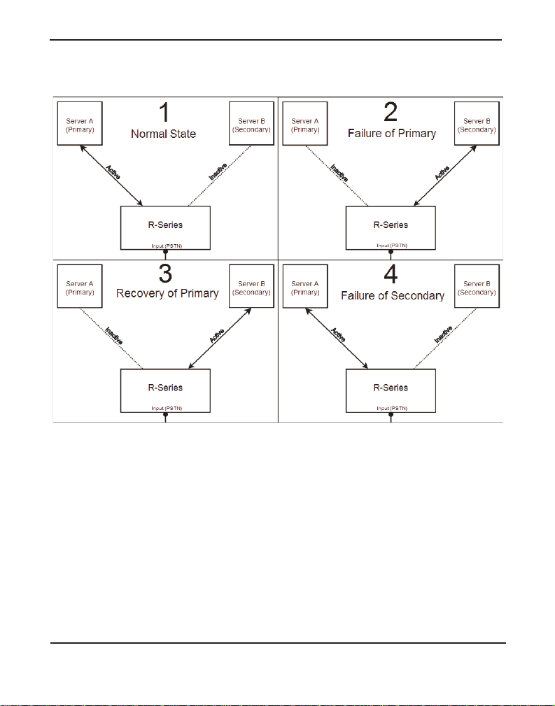
The basic application sequence shown below depicts the following:
1. While in a normal state, the R-Series unit r outes the input lines from
the PSTN to Server A (Primary).
2. After a failure of Server A, the R-Series unit routes the input lines
from the PSTN to Server B (Secondary).
3. After Server A re covers, the R-Serie s unit c ontin ues to route the in put
lines from the PSTN to Server B.
4. After a failure of Server B, the R-Series unit routes the input lines
from the PSTN to Server A.
Digiu m, In c . Page 12
Page 13
Chapter 1: Overview
Figure 1: Basic Application Sequence
There are a variety of applications where the R-Series units can prove
useful.
Digium, Inc. Page 13
Page 14

Chapter 1: Overview
What is Asterisk®?
Asterisk is th e world’s leading open source t elephony engine and tool kit.
Offering fle xibility unheard of in the world of proprietar y
communications, Asterisk empowers developers and integr ators to create
advanced communication solutions...for free. Asterisk is r eleased as open
source under the GNU General Public License (GPL), and it is available
for download free of charge. Asterisk is the most popular open source
telephony software available, with the Asterisk Community being the top
influencer in VoIP.
Asterisk as a Phone Switch (PBX)
Asterisk can be configured as the core of an IP or hybrid PBX, switching
calls, managing routes, enabling features, and conne cting callers with the
outside world over IP, analog (POTS), and digital (T1/E1/J1/BRI)
connections.
Asterisk runs on a wide variety of opera ting systems including Linux,
Mac OS X, OpenBSD, FreeBSD, and Sun Solaris. It provides all of the
features you would exp ect from a PBX inclu ding many adva nced featu res
that are often associate d with high end (and high cost) proprietary PBXs.
Asterisk's archi tecture is designed for maximum flexibilit y and supports
Voice over IP in many protocols, and can interoperate with almost all
standards-base d telephony equipment using relatively ine xpensive
hardware.
Asterisk as a Gateway
It can also be built out as the heart of a media gateway, bridging the
legacy PSTN to the expanding world of IP telephony. Asterisk’s modular
Digium, Inc. Page 14
Page 15

Chapter 1: Overview
architecture a llows it to co nvert between a wide ran ge of communicat ions
protocols and media codecs.
Asterisk as a Feature/Media Server
Need an IVR? Asterisk’s got you covered. How about a conference
bridge? Yep. It’s in there. What about an autom ated attendant? Asterisk
does that too. How about a replacement for your agi ng legacy voicemail
system? Can do. Unified messaging? No problem. Need a telephony
interface for your web site? Okay.
Asterisk in the Call Center
Asterisk has been adopted by call centers around the world based on its
flexibility. Call center and contact center developers have built complete
ACD systems based on Asterisk. Asterisk has also added new life to
existing call center solutions by adding remote IP agent capabilities,
advanced skills-based routing, predictive and bulk dialing, and more.
Asterisk in the Network
Internet Telephony Service Providers (ITSPs), Competitive Local
Exchange Ca rri ers (C LEC s ) an d eve n first -t ier incu m b en ts hav e
discovered the power of open source communications with Asterisk.
Feature servers, hosted services clusters, voicemail syste ms, and pre-paid
calling solution s, a ll based on Asterisk have helped reduce costs and
enabled flexibility.
Digium, Inc. Page 15
Page 16

Chapter 1: Overview
Asterisk Everywhere
Asterisk has become the basis for thousands of communications
solutions. If you need to communicate, Asterisk is your answer. For more
information on Asteris k, visit http://www.asterisk.org or http://
www.digium.com.
Digium, Inc. Page 16
Page 17

Chapter 2 Unit Installation
This chapter provides the following information:
Unpacking the Unit on page 18
Shipm en t Ins pec ti o n on page 19
Front Panel Identification on page 20
Unit Iden ti fica ti on on page 23
USB Requirements on page 24
Hardware Installation on page 25
Software Installation on page 30
Note: The R-Series unit ins t alla tion ins tru ct ions are wri t ten so that
they will apply to any model in the series. Examples and model
specific inf ormation are included as need ed .
Digiu m, In c . Page 17
Page 18

Chapter 2: Unit Installation
Unpacking the Unit
When you unpack your unit, carefully inspect it for any damage that m ay
have occurred in shipment. If damage is suspected, file a claim with the
carrier and contact the reseller from which the unit was purchased. If the
unit was purchased direct from Digium, c ontact Digium Te chnical
Support at +1.256.428.6161. Keep the original shipping container to use
for future shipment or proof of damage during shipment.
Note: Only qualified service personnel should install the unit. Users
should not attempt to perform thi s function themselves. The installer
must ensure that the equipment is reliably earth grounded in
accordance with the National Electrical Code.
This un i t is in t ended fo r in s t a ll ation in a Restricted Access
Location (RAL) only.
Digium, Inc. Page 18
Page 19

Chapter 2: Unit Installation
Shipment Inspection
The following items are includ ed in shipment of an R-Series unit:
R-Series unit
Two USB A-B cables
Rack mounting ears and four screws
Ground nut
Ground ring terminal
Warranty Statement
Quickstart Guide
Note: After inspecting the shipment, Digium highly recommends that
you register the unit for support eligibility. Please refer to Free
Installation Support on page 104 for additiona l information on how
to obtain assistance from Digium Technical Support.
Digium, Inc. Page 19
Page 20
Chapter 2: Unit Installation
Alternate I nput
(RJ21)
Input
Passthrough
Input
Primary
Secondary
Device Status
Device ID
USB Console
Primary USB
Secondary USB
Primary Status
Secondary Status
Input
Passthrough
Input
Primary
Secondary
Device
Status
Device ID
USB Console
Primary USB
Secondary USB
Primary Status
Secondary Status
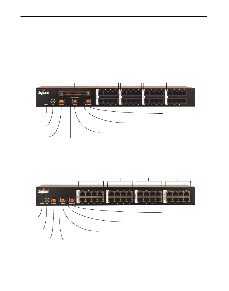
Front Panel Identification
This section describes the components on the front panels of the various
R-Series models.
Figure 2: R800 Analog Unit
Digium, Inc. Page 20
Figure 3: R850 Digital Unit
Page 21

Chapter 2: Unit Installation
Alter nate I np ut (o pt ion a l) - Provides an alternate method for con-
necting input lines using an RJ21 interface and is available only on
some analog models.
Note: The Alternate Input and Input co nnectors should not have
lines connected to them at the same time.
Input - These ports are used for connecting input lines, such as those
coming from the PSTN. A cable can be connected from each of these
ports to an input line. Digital models use an RJ45 interface. Analog
models use an RJ11 interface.
Passt hroug h In pu t (opti o nal ) - Thes e ports are gene rally connected
to the primary PBX for the purpose of front-ending a lega cy PBX connected to secondary ports. A cable can be connected from each of
these ports to a separate port on the primary PBX. Digital models use
an RJ45 interface. Analog models use an RJ11 interface.
Note: The Passthrough Input is reserved for future use.
Primary - These ports are used for routing the input lines to the pri-
mary PBX. A cable can be connected from each of these por ts to a separate port on the primary PBX. Digital model s use an RJ45 interface.
Analog models use an RJ11 interface.
Secondary - These ports are used for routing the input lines to the
secondary PBX. A cable can be connected from each of these ports to
a separate port on the secondary PBX. Digita l models use an RJ45
interface. Analog models use an RJ11 interface.
Device Status - This LED corresponds to the status of the R-Series
unit. See Troubleshooting on page 81 for more information.
Device ID - This dial should be set to a number whic h is unique across
all R-Series units that co-exist in an installation. The Device ID
assignment for your first device should be 0, second device should be
1, third device should be 2, and so on.
Digium, Inc. Page 21
Page 22

Chapter 2: Unit Installation
USB Console - This port can be used to access unit status, system
information, power the R-Series unit, and perform maintenance operations in ASCII Mode without disconnecting the Primary USB or Sec-
ondary USB ports. A USB A-B cable may be connecte d from this port
to a USB port on a computer. See ASCII Mode on page 87 for more
information.
Note: Any of the USB ports can be operated in ASCII Mode.
Primary Status - This LED corr es po nds to the status o f the Primary
connection made on Primary USB. See Troubleshooting on page 81
for more inform at i on.
Primary USB - This port is used for communicating with the Primary
PBX, powering the R - Se r i es unit, and accessing AS CII Mode. A USB
A-B cable should be connected from this por t to a USB port on the
Primary PBX. See ASCII Mode on page 87 for more information.
Secondary Status - This LED corresponds to the status of t he Second-
ary connection made on Secondary USB. See Troubleshooting on
page 81 for mor e information.
Secondary USB - This port is used for communicating with the Sec-
ondary PBX, powering the R-Series unit, and accessing AS CII Mode.
A USB A-B cable should be connect ed from this por t to a US B port on
the Secondary PBX. See ASCII Mode on page 87 for more inform ation.
Digium, Inc. Page 22
Page 23
Chapter 2: Unit Installation
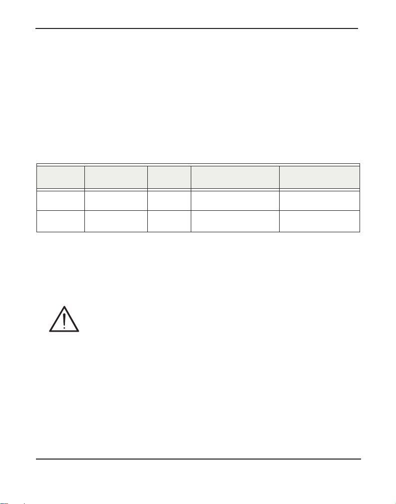
Unit Identification
The defining characteristic s of the R- Ser ie s models are whether t he uni t
supports analog or digit al lines, the number of ports supported, whether
the unit includes a Passthrough c onnector, and whether the unit supports
RJ21 for an alternate input method. See Table 1 for a list of the various
models.
Table 1: R-Series Models
Model Type Ports Passthrough RJ21 Input
R800 POTS 8 Yes Yes
R850 T1/E1/BRI 8 Yes Not Applicable
Note: Passthrough is reserved for future use.
Caution
Only qualified service personnel should continue with
hardware installation and confi guration of the R-Serie s unit.
Users should not at tempt to perf orm t hese f unct ions th emselve s.
Digium, Inc. Page 23
Page 24

Chapter 2: Unit Installation
USB Requirements
The servers which connect to an R-Series unit using the USB Console,
Primary USB, and Secondary USB ports must support USB 1. 1 or greater
for compatibility. If either server does not support at least USB 1.1, an RSeri e s unit w ill not work .
Digium, Inc. Page 24
Page 25

Chapter 2: Unit Installation
Hardware Installat ion
This section describes how to properly install the hardware for an RSeries unit.
Grounding
The R-Series unit must be properly grounded for safety reasons. If the
unit is not properly grounded, damage could arise to the R-Series unit
and/or other equipment connec ted to the R-Series unit. If an R-Series unit
is damaged while it is improperly grounded, the warranty on the R-Ser ies
unit is void.
A ground lug is located on the opposite side from the front panel of an RSeries unit. Attach an appropria te length and guage of wire to the ground
ring terminal. The wire length should be as short as possible, and guage
should be 18 AWG or greater . Stranded or solid wire is acceptable. Wire
is not provided with the R-S eries unit . Slide the ground ring term inal ove r
the ground lug. Then fasten the ground rin g terminal to the ground lug
using the groun d nut. The ground nut must be turned clockwise to tighten
it onto the ground lug. The opposite end of the wire that is connected to
the ground ring terminal should be secur ily fastened to an unpainted
metalic section of a properly grounded server rack. A connector for the
opposite end of the wire is not provided with the R-Series unit.
Note: Taking into consideration the requir ements of a ll equipment that
is connected to or sharing the rack, the server rack should be properly
grounded. Refer to the manufacturer of the rack for instructions on
how to properly ground the rack.
Digium, Inc. Page 25
Page 26

Chapter 2: Unit Installation
Mounting
Place one of the rac k mounting ears on the right side of the R-Series unit.
Line up the hol es from the rack m ountings e ar to the t hreaded hole s o n the
side of the R-Series unit. Two screws should be inserted and turned
clockwise to fasten the rack mounting ear. Repeat these steps when
installing a rack mounting ear on the left side of the R-Series unit.
A typical equipment rack installation would have an R-Series unit
mounted on the opposite side of the rack as the servers. Use 2 screws on
each rack mounting ear to secure the R-Series unit to a rack.
Setting Dev ice I D Dial
The Device ID dial should be set to a number which is unique across all
R-Series units that co-exist in an installation. The Device ID assignment
for your first device should be 0, second device should be 1, third device
should be 2, and so on.
Connecting Ports (Powering the Unit)
A description of each of the front panel connectors on an R-Series unit is
available in the section titled Front Panel Identification on page 20.
Please refer to that section to determine what should be connected to each
connector.
Connections to an R-Series unit should be made in the following order.
1. Primary
2. Secondary
Digium, Inc. Page 26
Page 27

Chapter 2: Unit Installation
3. Passthr ough Input (optional) - Reserved for future use.
4. Input or Alternate Input (n ot both)
5. Primary USB
6. Secondary USB
7. USB Console
An R-Series unit will receive powe r from any of the thre e USB
connections (USB Console, Primary USB, Secondary USB). No othe r
power source is required.
Note: You may have t o apply a decent amount of force to disconnect a
USB cable from an R-Series unit. This is normal. The USB connectors
used in the R-Series units are high-retenti on to help prevent accidental
disconnection.
General Recommendations
Using an R-Series unit in conjunction with a USB hub may have
undesirable resul ts.
Each server connected to an R-Series unit should be powered from a
different powe r source.
It is highly recommended that each server co nnected to an R-Series unit
be equipped with sufficient surge protection to reduce the risk of damage
to the server and R-Series unit.
It is recommended that e ach server whic h is connec ted to an R-Seri es unit
be equipped with an uninterruptible power supply that has sufficient
reserve capacity to power the server until electricity is restor ed. A
generator may also be use d as an alternate means of powering the se rvers
while mains power is out.
Digium, Inc. Page 27
Page 28
Chapter 2: Unit Installation
Caution
This unit must be connected to the Teleco mmu nications
Network in your country using an approved line cord, e.g.: for
Australia use only line cords complying with ACA Technical
Standard TS008.
Caution
Connect only equipment approved for use in your specifi c
country to the telecommunications ne twork voltage circuit
ports.
Verification
Note: The following steps need to be performed on all Asterisk nod es
which are connected to an R-Series unit. In addition, all command-line
applications mentione d in this manual must be executed as the root
user.
Log in and e xecute the following command to list the devices detected by
the USB controller:
# lsusb
Digium, Inc. Page 28
Page 29

Chapter 2: Unit Installation
Confirm that the output from lsusb lists a device with a USB vendor ID
of “10c4”. The screen output should be similar to the following:
Bus 003 Device 002: ID 10c4:<device identifier>
Cygnal Integrated Products, Inc. CP210x Composite
Device
In the USB device listing shown above, <de vice identifier> will be
populated with one of the identifiers listed in the table below.
Note: Unit identifiers are the same for all R-Series models.
Table 2: Unit Identifiers
Model Identifier
R800
R850
ea60
ea60
A Digium R-Series (R800 / R850) unit identifier should be listed. If a
matching unit identifie r is not listed, then your machine is not USB 1.1 (or
higher), and the unit will not work with your motherboard.
Digium, Inc. Page 29
Page 30

Chapter 2: Unit Installation
Softw a r e In s t al la t io n
While the R-Series units do not requi re DAHDI drivers in order to
function, DAHDI drivers and other libraries may need to be installed in
order for other Digium hardware products to function when connected to
an R-Series u nit.
Digium hardware which relies on DAHDI requires drivers and libraries
that are not integrate d with the Linux kernel. Digium hardware is only
supported under Linux. Digium recommends CentOS, Debian, Red Hat,
and Ubuntu distrib utions of Li nux. However, many other dis tributi ons a re
supported by Digium Technical Suppor t.
Digium’s software, including drivers and application software, may be
obtained from Digium’s download servers at :
http://downloads.digium.com
http://downloads.asterisk.org
For an introduction to Asterisk, Digium’s telephony software, including
additional infor mation on its configuration, setup, and fea tures, please
refer to:
http://www.asterisk.org
For the latest information on se tting up and configuring DAHDI drivers
for your Digium hardware products, please refer to the latest release of
your products’ manuals which are available from the product-specific
documentation secti on at:
http://www.digium.com
Digium, Inc. Page 30
Page 31

Chapter 2: Unit Installation
T o install your R-Series unit for use with other Digium hardware that
relies on DAHDI, you will need:
Linux 2.6 kernel headers
Development libraries and headers f or ncurses
Development libraries and headers f or zlib and openssl
Development libraries and headers f or newt
GCC and standard software build tools
Subversion
Terminal emulation program such as Minicom (optional)
It is recommended that you use the most recent version of the Asterisk
software for the best results . If you have pre viously installed this, Digium
recommends that you upgrade to the latest “-current” version.
Additional softwar e installation steps are described in Chapter 3—
“Configuration”.
Digium, Inc. Page 31
Page 32

Chapter 3 Configuration
The R-Series units have a variety of configuration options. This chapter
provides sample configur ations to demonstrate customizing the unit to
meet your individual needs. Each section explains basic options as
examples. Once you have familiarized yourself with the examples, you
can modify them to meet your specific needs.
Digiu m, In c . Page 32
Page 33

Chapter 3: Configuration
Understanding Serial Device Assignments
When the Console, Primary, or Secondary USB ports on the R-Serie s uni t
are connected to a system, a device file associated with the R-Series unit
should automatically be create d that is visible from the filesystem of that
system. In most case s, the defa ult device file a ssig nment for the first seri al
device connected over USB is ttyUSB0 in the /dev directory. Th e second
serial device connecte d over USB is ttyUSB1, and so on. This does not
correlate t o the Device ID Dial setting of the R-Series unit. It is important
to know the device file assignment of the R-Serie s unit that is being
configured.
Note: During installation of the R-Series command-line uti lity, rctl,
udev rules will be installed whic h will automatically map the R-Series
unit’s device file of /dev/ttyUSB[#] to /dev/rseries[#]. For
/dev/rseries[#], the # is the Device ID Dial assignment of the R-Series
unit. For example, an R-Series unit with a Devic e ID Dial assignment
of 0 will have a device file associat ed at /dev/rseries0. We highly
recommend referencing /dev/rseries[#] instead of /dev/ttyUSB[#]
where possible. The rctl utility will be installed at a later point in the
manual.
Digium, Inc. Page 33
Page 34

Chapter 3: Configuration
R-Series Control Utility
Digium provides the source code for the R-Series control utility. This
software should be instal led on both the primary and secondary node. In
the examples shown throughout thi s manual, substitute the X.X.X in
rseries-X.X.X with the version of the R-Series source package.
# cd /usr/src
# wget http://downloads.digium.com/pub/telephony/
rseries/rseries-current.tar.gz
# tar zxvf rseries-current.tar.gz
# cd rseries-X.X.X
# make
# make install
Basic Functional Testing
Execute the following commands to query basic information from the
R-Series unit.
# cd /usr/src/rseries-X.X.X/
# ./rtest.sh info /dev/rseries[#]
Digium, Inc. Page 34
Page 35

Chapter 3: Configuration
Output similar to the following is nor mal after executing this command.
R-Series hardware is detected!
Firmware version: 4
Serial number: DM***********
Product number: R850
Ports: 8
ID Switch: 0
Watchdog Timeout (get): 129
Port 1: 0, primary, T1/E1
Port 2: 0, primary, T1/E1
Port 3: 0, primary, T1/E1
Port 4: 0, primary, T1/E1
Port 5: 0, primary, BRI
Port 6: 0, primary, T1/E1
Port 7: 0, primary, T1/E1
Port 8: 0, primary, T1/E1
The following test will change the state of all relays from Primary to
Secondary. Then it will change the state of all relays from Secondary to
Primary. Lastly, it will ch ange the state of each relay, one at a tim e, and
verify that the state change was successf ul. Execute the following
command to test relay state changes for the R-Series unit.
# ./rtest.sh tests /dev/rseries[#]
Digium, Inc. Page 35
Page 36

Chapter 3: Configuration
Output similar to the following is nor mal after executing this command.
R-Series hardware is detected!
Executing these tests will disconect any in
progress calls!
Type 'YES' to continue
If you wish to proceed, you must type YES in all upper-case. Output
similar to the following is normal after pressing Enter.
Getting control and setting all ports to primary
Getting control and setting all ports to secondary
Getting control and setting all ports to primary
Switching relays one at a time
Getting control and setting port 1 to
secondary...Success!
Getting control and setting port 1 to
primary...Success!
Getting control and setting port 2 to
secondary...Success!
Getting control and setting port 2 to
primary...Success!
Digium, Inc. Page 36
Page 37

Chapter 3: Configuration
Getting control and setting port 3 to
secondary...Success!
Getting control and setting port 3 to
primary...Success!
Getting control and setting port 4 to
secondary...Success!
Getting control and setting port 4 to
primary...Success!
Getting control and setting port 5 to
secondary...Success!
Getting control and setting port 5 to
primary...Success!
Getting control and setting port 6 to
secondary...Success!
Getting control and setting port 6 to
primary...Success!
Getting control and setting port 7 to
secondary...Success!
Getting control and setting port 7 to
primary...Success!
Digium, Inc. Page 37
Page 38

Chapter 3: Configuration
Getting control and setting port 8 to
secondary...Success!
Getting control and setting port 8 to
primary...Success!
Digium, Inc. Page 38
Page 39

Chapter 3: Configuration
Automatic Failover Configuration
This section describes a particular method for configuring an R-Series
unit for automatic fail over which is supported by Digium. This method
provides automatic fai lover for the following situations.
A software failure resulting in Aster isk no longer running.
A hardware or software failure resulting in the host soft ware no longe r
being able to communicate to the host softwa re running on the other
node.
The following components are continuously replicated between nodes.
Asterisk configuration file s, voicemails, AstDB, and logs
The following components are transferred from the active node to the
standby node during an automatic failover.
PSTN connections
Floating IP address
Note: Applications and devices should reference the float ing IP
address to connect to the active node instead of the node’s normal IP
address. The floating IP address is shared between the primary and
secondary node. The primary node will start off by listening on the
floating IP address. The floating IP addr ess will not be assigned on the
secondary node during this time. In the event that the primary node
fails, the cluster manager will automatically promote the secondary
node and assign the floating IP addr ess to it. Applic ation connections
will break and then reconnect to the floating IP address again, which
points to the secondary node.
Digium, Inc. Page 39
Page 40

Chapter 3: Configuration
Automatic Failover Scenario
In this scenario, a PBX has been deployed with two machine s that are
either identi cal, or suffici ent ly co m parab l e su ch that eith er mach in e can
act as the primar y PBX at any given tim e. Thi s scena ri o des crib es wh at
happens when a fatal hardware failure is experienced on the machine
acting as the primary node.
Actors
PSTN
R-Series unit (digital versi on)
PBX A
PBX B
Figure 4: Automatic Failover Scenario
Digium, Inc. Page 40
Page 41

Chapter 3: Configuration
Preconditions
PBX A and PBX B are running the host software described in thi s sec-
tion
PBX A is acting as the primary node
– Asterisk is running on PBX A
– The R-Series unit ha s the T1(s ) rou te d to PBX A
– IP traffic is directed to PBX A
PBX B is acting as a standby node for PBX A
Trigger
PBX A exp er ie nces a fata l hardw a re fai lu re (l ose s po wer)
General Flow
1. The host software on PBX B detects that PBX A has left the cluster
2. The host software on PBX B instructs the R-Series unit to direct the
T1(s) to PBX B
3. The host software on PBX B activates the floating IP address locally
4. The host software on PBX B starts Asterisk
5. PBX A comes back online and rejoins the cluster as a stand by for
PBX B
Digium, Inc. Page 41
Page 42

Chapter 3: Configuration
Host Software Components
The host software utilized for this method of automatic failover is
comprised of Pacemaker, Corosync, and DRBD. A brief description of
each of these components is liste d belo w.
Pacemaker - “Pacemaker is an Open Source, High Availabili ty resour ce
manager suitable for both small and large clusters. Hardware and
application failures can result in prolonged downtime and impact your
bottom line. In the event of a failure, resource managers like Pacemaker
automatically ini tiate recovery and make sure your application is
available from one of the remaning machines in the cluster. Your users
may never eve n know there was a problem.” - www.clusterlabs.org
Corosync - “The Corosy nc Cluster Engine is a Group Communication
System with additional fe atures for implementing high availability within
applications. The project provides four C Application Programming
Interface features:
A closed process group communication model with virt ual synchrony
guarantees for creating re plicated state machines.
A simple availability manager that restarts the applicat ion process
when it has failed.
A configuration and statistics in-memory database that prov ides the
ability to set , retrieve, and receive change notifications of information.
A quorum system that notifies applications when quorum is achieved
or lost.” - www.corosync.org
Digium, Inc. Page 42
Page 43

Chapter 3: Configuration
DRBD - “DRBD refers to block devices designed as a building block to
form high availability (HA) clusters. This is done by mirroring a whole
block device via an assigned netwo rk. DRBD can be understo od as
network based raid-1.” - www.drbd.org
Digium, Inc. Page 43
Page 44

Chapter 3: Configuration
Failure Detecti on
Pacemaker will be configured to periodically poll the resource agent in
charge of the Asterisk process. One of the required interfaces of a
resource agent is to be able to return the status of the resource.
The cluster me ssaging l ayer, Corosync, is in c har ge of determ ining cl uster
membership. If it loses contact with another node for any reason, it will
decide that it has failed and failover will be initiated.
Digium, Inc. Page 44
Page 45

Chapter 3: Configuration
Resource Management
Pacemaker manages resources in a cluster. A resource agent (RA) is a
utility used by Pacemaker to take car e of the deta ils of managing a
resource. For our purposes, P acemaker is managing resources in a twonode cluster.
Table 1: Res ource Management
Requirement Resourc e Agents Description
Asterisk ocf:Digium:ast erisk Asterisk RA
Asterisk
filesystem
ocf:linbit:drbd
ocf:heartbeat:Filesystem
DRBD link to sha re a
filesystem with
configuration/log/spool
directories and astdb.
PSTN
connections
Floating IP
ocf:Digium:rseries Handled via R-Series
hardware
ocf:heartbeat:I Paddr2 For VoIP connectivity
address
Digium, Inc. Page 45
Page 46

Chapter 3: Configuration
Installation
This sections decrib es the in stallatio n proce dure for eac h component used
by this automatic failover method.
Warning! It is CRITICAL
that the installation and configuration
steps be followed in the order stated without any deviation. Read the
instructions in their entirety. Do not skip steps!
Warning! We highly recom mend
that the hardware specifications
and software versions on all nodes be identical.
Warning! We highly recom mend
using either the CentOS 5.6,
Debian wheezy, or Ubuntu 10.04 (Lucid) Linux distribution on the
primary and secondary node. Distributions with specific versions
mentioned were used during Digium’ s te sting of the automatic failove r
scenario described in this chapter.
Warning! We highly recommend
that Asterisk not be installe d on the
secondary node until afte r everything else is installed and configured.
It is acceptable for Asterisk to already have been installed on the
primary node.
Warning! The auto ma tic fai lo v er scen ar io d escri b ed in thi s chap te r
requires that the Aster isk con figuration be stored in flat files. This
scenario will not work with an Asterisk configuration that is stored in
Realtime (e.g. SQL database).
Warning! The auto ma tic fai lo v er scen ar io d escri b ed in thi s chap te r
supports an Asterisk setup tha t uses Asterisk Business Edition, Skype
for Asterisk, Fax for Asterisk, G.729, HPEC, and any other Digium
product that requir es regist ration using th e Digi um register utili ty only
when additional license s have already been purchased and registered
on the secondary node.
Digium, Inc. Page 46
Page 47

Chapter 3: Configuration
DRBD
A USB flash drive will need to be installed on both the primar y and
secondary node f or storing DRBD data. It is acceptable for the USB flash
drives to not be of identical size as long as the smalle st USB flash drive is
at least 1GB in size. The USB flash drives must be large enough to store
all data for Asterisk.
Note: USB flash drives are not provided with an R-Series unit. They
must be purchased separately.
First, locate the device file that is created for each USB flash drive by
executing dmesg on both the primary and secondary node. Look through
the output of dmesg to locate the USB flash drive device file assignment.
Digium, Inc. Page 47
Page 48

Chapter 3: Configuration
Output identifying your USB flash drive device file may look similar to
the following.
Vendor: 3System Model: USB Flash Disk Rev:
1.00
Type: Direct-Access ANSI
SCSI revision: 02
SCSI device sdb: 3989775 512-byte hdwr sectors
(2043 MB)
sdb: Write Protect is off
sdb: Mode Sense: 00 06 0c 76
sdb: assuming drive cache: write through
SCSI device sdb: 3989775 512-byte hdwr sectors
(2043 MB)
sdb: Write Protect is off
sdb: Mode Sense: 00 06 0c 76
sdb: assuming drive cache: write through
sdb: sdb1
sd 2:0:0:0: Attached scsi removable disk sdb
sd 2:0:0:0: Attached scsi generic sg1 type 0
The output shown above for this example identifies the USB flash drive
being assigned a device file at /dev/sdb.
The data on both USB flash drives must be “zeroed out” before
initializing DRBD. Execute the following command on both the primary
Digium, Inc. Page 48
Page 49

Chapter 3: Configuration
and secondary node to “zero out” a USB flash drive and irreversibly
destroy all data on it.
# dd if=/dev/zero of=/dev/[USB_flash_device] bs=1M
Warning! All data on this device will be permanently lost!
Depending on the size of the USB flash drive, completion of this
command may take a long time ( e. g. several minutes to several hours).
Output similar to the following is nor mal after executing this command.
dd: writing `/dev/sdb': No space left on device
1949+0 records in
1948+0 records out
2042764800 bytes (2.0 GB) copied, 633.794 seconds,
3.2 MB/s
USB flash drives of dif ferent siz es may be used. Regar dless of whether or
not they are the same size, partitions must be created on both USB flash
drives that are of identical siz e and completely empty. The disk partition
type must be Linux (0x83).
Note: It is highly recommended that the partition for DRBD be 1GB
or larger.
Digium, Inc. Page 49
Page 50

Chapter 3: Configuration
Execute the following command on both the pr imary and secondary node
to create a partition on the USB flash drive for DRBD.
fdisk /dev/[USB_flash_device]
Output similar to the following is nor mal after executing this command.
Device contains neither a valid DOS partition
table, nor Sun, SGI or OSF disklabel
Building a new DOS disklabel. Changes will remain
in memory only,
until you decide to write them. After that, of
course, the previous
content won't be recoverable.
Warning: invalid flag 0x0000 of partition table 4
will be corrected by w(rite)
Command (m for help):
Issue the following commands to the fdisk application:
Press n for new partition.
Press p for primary partition.
Press 1 forst first partition number.
Press 1 for fi rst cyclinder.
If both USB flash drives are of identical size, press Enter for last cyl-
inder. If the are of differing size, use a variation of the example
“+1024M” for a 1,024MB (1GB) partition.
Press w to write changes.
Digium, Inc. Page 50
Page 51

Chapter 3: Configuration
Output similar to the following is nor mal after executing these
commands.
The partition table has been altered!
Calling ioctl() to re-read partition table.
Syncing disks.
In most cases, the partition created on the USB flash drive will be
assigned /dev/[USB_flash_device]1. This can be confirmed by executing
the following command and verifying that the devic e file for the partit ion
exists.
# ls /dev/[USB_flash_device]*
Note: The device file assigned to the USB flash drive’s partition
will be referenced at a later point in the manual. It is important to
take note of this assignment.
Digium, Inc. Page 51
Page 52

Chapter 3: Configuration
Most Linux distributio ns should provide packages for DRBD. This
package should be install ed on both the primary and secondary node.
Debian / Ubuntu
# apt-get install drbd8-utils
Red Hat Enterprise Linux 5 / CentOS 5
# yum install drbd83 kmod-drbd83
Note: Do not start the DRDB service at this time.
Pacemaker & Corosync
Like DRBD, packages sho uld be provide d by mo st Li nux distr ibu tions f or
Pacemaker and Corosync. These packages should be installed on both the
primary and secondary node.
Debian / Ubuntu
# apt-get install corosync pacemaker
Red Hat Enterprise Linux 5 / CentOS 5
Note: The clusterlabs.org repository requires a package that is in the
EPEL repository. Digium recommends installing the individual
package manually, rather than setting up the EPEL repo. Replace
Digium, Inc. Page 52
Page 53

Chapter 3: Configuration
[arch] with e ither i386 or x86_64, depending on your system’s
architecture.
# wget http://download.fedora.redhat.com/pub/epel/
5/[arch]/libesmtp-1.0.4-5.el5.[arch].rpm
# rpm -Uvh libesmtp-*.rpm
# wget -O /etc/yum.repos.d/pacemaker.repo http://
clusterlabs.org/rpm/epel-5/clusterlabs.repo
# yum install pacemaker corosync
Note: Do not start the Pacemaker or Corosync service at this time.
Digium, Inc. Page 53
Page 54

Chapter 3: Configuration
Digium Resource Agents
Digium provides the source code for the resource agents for the R-Series
unit and Asterisk, as well as sample configuration files for DRBD and
Corosync. The sample configuration files will need to be modified, but
should help you to get started. This software should be installed by
executing the following c ommands on both the primary and secondary
node.
# cd /usr/src/rseries-X.X.X/
# make samples
Note: If you receive a message stating that the
/etc/corosync/corosync.conf file already exists and will not be
replaced, you will need to backup the corosync.conf file located in the
/etc/corosync directory, and then manually copy the example
corosync.conf file to th e /etc/corosync directory.
Digium, Inc. Page 54
Page 55

Chapter 3: Configuration
Configuration
The configuration instructions in this section assume that the sample
configuration file s previously mentioned were installe d.
Note: In the following examples, the node hostnames are specified as
astnode1 and astnode2. You must replace all instances of these with
the hostnames o f your node s. This mus t exact ly match the host name of
your nodes. An IP address cannot be used here. If the hostname is not
set for the primary or secondary node, it may be set by exec uting
hostname [hostname].
DRBD
DRBD works by acting as a middle-man be tween a filesystem a nd a disk.
The filesystem lives on DRBD, which lives on a disk partition.
The DRBD package provided by some Linux distribut ions may not
include a working /etc/drbd.conf file. Ensure this file contains the
following lines on both the primary a nd secondary node.
include "drbd.d/global_common.conf";
include "drbd.d/*.res";
The /etc/drbd.d/asterisk.res file contains the configuratio n for the DRBD
resource named asterisk. This c onfiguration file must match on both the
primary and secondary node. The following settings in this file must be
modified to reflect your setup.
The e-mail address on the split-brain line is where e-mail will be sent
when DRBD detects a conflict that resulted in a split-brain (refer to
DRBD project documentation for det ai ls on split-brain). The value
Digium, Inc. Page 55
Page 56

Chapter 3: Configuration
should be changed to an e -mail address that is monitore d by an administrator. This requires that a Mail Tr ansport Agen t be install ed, such as
the one provided in the libesmtp pack age that was previously downloaded and installed. On many Linux distributions, a package named
sendmail is also available.
Replace all instances of the example hostnames with the hostnames of
your nodes. This must exactly match the hostna me of your nodes. An
IP address c annot be used here . If the hostna me is not set f or either the
primary or secondary node, it may be set by executing hostname
[hostname].
The device lines must point to the DRBD device node. This will usu-
ally be /dev/drbd0.
The partition on the disk lines must refer to the partition that you cre-
ated for DRBD on each node.
The IP address on the address lines must be changed to the real (non-
floating) IP address es of each node.
Execute the following command on both the pr imary and secondary node
to create meta dat a on dis k for DR BD.
# drbdadm create-md asterisk
Digium, Inc. Page 56
Page 57

Chapter 3: Configuration
Output similar to the following is nor mal after executing this command.
--== Thank you for participating in the global
usage survey ==-The server's response is:
you are the 13356th user to install this version
Writing meta data...
initializing activity log
NOT initialized bitmap
New drbd meta data block successfully created.
success
Note: In order for DRBD to properly function, the firewall
configuration (e.g. iptables) on both the primary and secondary node
must allow incoming traff ic on TCP port 7789 from the other node. If
you are using iptables, you may flush all iptables rules by executing
iptables -F after every reboot. Alternatively, you can permanently
disable particula r iptables rules by editing the iptables co nfiguration
file on each node. Depending on the Linux distribution, the iptables
configuration file may be located at /etc/sysconfig/iptables or /etc/
network/interfaces.
Then execute the following command on both the primary and secondary
node to start the DRBD service.
# /etc/init.d/drbd start
Digium, Inc. Page 57
Page 58

Chapter 3: Configuration
Output similar to the following is nor mal after executing this command.
Starting DRBD resources: [
asterisk
Found valid meta data in the expected location,
1027674112 bytes into /dev/sdb1.
d(asterisk) n(asterisk) ]..
On only the primary node, generate a new UUID and create a new ext3
filesystem for DR BD. [drbd_device] should usually be repla ced with
/dev/drbd0.
Note: This should be done only on the primary node.
# drbdadm disconnect asterisk
# drbdadm -- --clear-bitmap new-current-uuid
asterisk
# drbdadm -- --overwrite-data-of-peer primary
asterisk
# mkfs.ext3 -m0 [drbd_device]
# drbdadm secondary asterisk
# drbdadm detach asterisk
# drbdadm up asterisk
Digium, Inc. Page 58
Page 59

Chapter 3: Configuration
Before proceeding t o the ne xt secti on, verify t hat DRBD f ile r eplica tion is
functioning properly by e xecuting the following commands.
Primary Node
The following commands should be execut ed only on the primary node.
# drbdadm primary asterisk
# mkdir /mnt/asterisk
# mount -t ext3 [drbd_device] /mnt/asterisk
# cd /mnt/asterisk
# touch test
# ls
Confirm that the file ‘test’ exists.
# cd
# umount /mnt/asterisk
# drbdadm secondary asterisk
Digium, Inc. Page 59
Page 60

Chapter 3: Configuration
Secondary Node
The following commands should be executed only on the secondary node.
# drbdadm primary asterisk
# mkdir /mnt/asterisk
# mount -t ext3 [drbd_device] /mnt/asterisk
# cd /mnt/asterisk
# ls
Confirm that the file ‘test’ exists. If the ‘test’
file exists, file replication to the secondary node
was successful. The ‘test’ file is the same ‘test’
that was created on the primary node.
# cd
# umount /mnt/asterisk
# drbdadm secondary asterisk
Digium, Inc. Page 60
Page 61

Chapter 3: Configuration
Asterisk & DAHDI
Since the configuration files for Asterisk are stored on the DRBD
filesystem, this filesystem must be mounted in order to make changes.
The filesystem is always mounted on the cur rently active node, which
means that any changes will need to be made there. The changes will
automatically be copied to the standby node, over the DRBD link.
The createlinks.sh script has been included which will easily create
symbolic links from several Aste risk files and directories on the host
filesystem to the appropriate places on the DRBD filesystem.
Warning! If these files and/or directories exist on the host filesystem
and do not exist on the DRBD filesystem, they will be moved to the
DRBD filesystem. It is highly recommended that these commands be
executed before Asteri sk is installed on the secondary node.
Note: For the sake of convenience, DAHDI will be installed and
configured in this section. DAHDI configuration files are not
replicated between nodes. In addition, DAHDI is not handled by this
failover scen ar io.
Digium, Inc. Page 61
Page 62

Chapter 3: Configuration
Primary Node
The following commands should be execut ed only on the primary node.
[drbd_device] shoul d usually be replaced with /dev/drbd0.
# cd /usr/src/rseries-X.X.X
# drbdadm primary asterisk
# mount -t ext3 [drbd_device] /mnt/asterisk/
# ./createlinks.sh
If Asteri sk is not curr ently in stalled, createlinks.sh will not generate any
output after it is executed. If Asterisk is currently installed, output
similar to the following is normal after executing createlinks.sh.
Moving /etc/asterisk/ to /mnt/asterisk/
etcasteriskdir/
mkdir: cannot create directory `/mnt/asterisk/
etcasteriskdir': File exists
Moving /var/log/asterisk to /mnt/asterisk/logdir/
mkdir: cannot create directory `/mnt/asterisk/
logdir': File exists
Moving /var/spool/asterisk/ to /mnt/asterisk/
spooldir/
mkdir: cannot create directory `/mnt/asterisk/
spooldir': File exists
Digium, Inc. Page 62
Page 63

Chapter 3: Configuration
Before proceeding, verify that the createlinks.sh script suc cessfully
created the appropriate directories under /mnt/asterisk. This can be
accomplished by executi ng the following command.
# ls -alh /mnt/asterisk/
The output from this command should show that at least the following
directories exist .
etcasteriskdir
logdir
spooldir
Digium, Inc. Page 63
Page 64

Chapter 3: Configuration
Note: If Libpri, DAHDI, and Asterisk are currently installed on
the primary node , the following steps will need to be completed on
the primary node.
If the Asterisk init script is installed (/etc/init.d/asterisk), it will need
to be disabled in order to not conflict with the automatic failover configuration. This can be accomplished by executing chkconfi g --d el
asterisk on Red Hat based distributions and update-rc.d -f asteri sk
remove on Debian based distr ibutions.
If the DAHDI init script is not already installed (/etc/init.d/dahdi),
execute make config in the DAHDI source directory to install it.
Execute drbdadm secondary asterisk.
Digium, Inc. Page 64
Page 65

Chapter 3: Configuration
Note: If Libpri, DAHDI, and Asterisk are not currently installed
on the primary node, proceed with the steps below. Otherwise,
skip these ste ps an d pro cee d with the s tep s for the secondar y
node on page 69.
Download the late st version of Libpr i. Substitute th e version of Libpri f or
the X.X in the command-line below. Libpri is available for download
from:
http://downloads.asterisk.org/pub/telephony/libpri
# wget http://downloads.asterisk.org/pub/telephony/
libpri/libpri-X.X-current.tar.gz
Note: There is no correlation between the versioning of Libpri and
Asterisk. The Libpri 1. 4 branch wil l fu nction with the Asteris k 1.6 and
1.8 branches.
Expand the downloade d file, compil e its content s, and instal l the l ibrarie s.
Substitute the version of Libpri for the X.X and X.X.X.X in the
com mand-line s below.
# tar -zxvf libpri-X.X-current.tar.gz
# cd libpri-X.X.X.X/
# make
# make install
Digium, Inc. Page 65
Page 66

Chapter 3: Configuration
Download the latest DAHDI drivers with tools. DAHDI is available for
download from:
http://downloads.asterisk.org/pub/telephony/dahdi-linux-complete
# wget http://downloads.asterisk.org/pub/telephony/
dahdi-linux-complete/dahdi-linux-completecurrent.tar.gz
Expand the downloaded file, compile its contents, and install the drivers
and tools. Substitute the version of DAHDI for the X.X.X in the
com mand-line s below.
# tar -zxvf dahdi-linux-complete-current.tar.gz
# cd dahdi-linux-complete-X.X.X+X.X.X
# make
# make install
# make config
Then configure DAHDI according to the instr uc tions provided in the
product manual(s) for the installed Digium hardware. After configuring
DAHDI, load the DAHDI kernel modules according to the instr uctions
provided in the product manual(s) for the installed Digium hardware.
Digium, Inc. Page 66
Page 67

Chapter 3: Configuration
Download the latest relea se ver sion of Asterisk. Substitute the version of
Asterisk for the X. X.X in the command below. Asterisk is availab le fo r
download from:
http://downloads.asterisk.org/pub/telephony/asterisk
# wget http://downloads.asterisk.org/pub/telephony/
asterisk/asterisk-X.X.X-current.tar.gz
Expand the dow nl oad ed file , compile its contents , and insta l l the
application. Substitut e the version of Asterisk for the X.X.X and X.X.X.X
in the command-lines below.
# tar -zxvf asterisk-X.X.X-current.tar.gz
# cd asterisk-X.X.X.X/
# ./configure
# make
# make install
Note: Do not run “make config” for the Asterisk installation on the
primary node. The automatic failover setup described in this chapter
can start and stop Asterisk without the init script provided by “make
config”. The init script may conflict with the automatic failover setup.
Digium, Inc. Page 67
Page 68

Chapter 3: Configuration
If this is the first Asterisk installation on this system, you should install
the sample configurati on files. To do this, run:
# make samples
Note: Running this command will overwrite, after making a backup
copy, any older Asterisk configura tion files that you have in the
/etc/asterisk directo ry.
If your installation has failed, it may be because you are missing one or
more of the build dependencies, the kernel headers, or the development
tools. Contact your reseller where the unit was purchased, or call Digium
Technical Support at 1.256.428.6161 for assistance. Please refer to Free
Installation Support on page 104 for additiona l information on how to
obtain assistance from Digium Technical Support.
After installation is complete, execute the following commands.
# umount /mnt/asterisk/
# drbdadm secondary asterisk
Digium, Inc. Page 68
Page 69

Chapter 3: Configuration
Secondary Node
The following commands should be executed only on the secondary node.
[drbd_device] shoul d usually be replaced with /dev/drbd0.
Note: If Asterisk is currently installed on the secondary node, the
createlinks.sh script will fail. As stated previously on page 46,
Asterisk should not alrea dy be installed on the secondary node, and
software versions betwe en the primary and secondary node should be
identical.
# cd /usr/src/rseries-X.X.X
# drbdadm primary asterisk
# mount -t ext3 [drbd_device] /mnt/asterisk/
# ./createlinks.sh
Output similar to the following is nor mal after executing the last
command.
mkdir: cannot create directory `/mnt/asterisk/
etcasteriskdir': File exists
mkdir: cannot create directory `/mnt/asterisk/
logdir': File exists
mkdir: cannot create directory `/mnt/asterisk/
spooldir': File exists
Digium, Inc. Page 69
Page 70

Chapter 3: Configuration
Download the late st version of Libpr i. Substitute th e version of Libpri f or
the X.X in the command-line below. Libpri is available for download
from:
http://downloads.asterisk.org/pub/telephony/libpri
# wget http://downloads.asterisk.org/pub/telephony/
libpri/libpri-X.X-current.tar.gz
Note: There is no correlation between the versioning of Libpri and
Asterisk. The Libpri 1. 4 branch wil l fu nction with the Asteris k 1.6 and
1.8 branches.
Expand the downloade d file, compil e its content s, and instal l the l ibrarie s.
Substitute the version of Libpri for the X.X and X.X.X.X in the
com mand-line s below.
# tar -zxvf libpri-X.X-current.tar.gz
# cd libpri-X.X.X.X/
# make
# make install
Download the latest DAHDI drivers with tools. DAHDI is available for
download from:
http://downloads.asterisk.org/pub/telephony/dahdi-linux-complete
# wget http://downloads.asterisk.org/pub/telephony/
dahdi-linux-complete/dahdi-linux-completecurrent.tar.gz
Digium, Inc. Page 70
Page 71

Chapter 3: Configuration
Expand the downloaded file, compile its contents, and install the drivers
and tools. Substitute the version of DAHDI for the X.X.X in the
com mand-line s below.
# tar -zxvf dahdi-linux-complete-current.tar.gz
# cd dahdi-linux-complete-X.X.X+X.X.X
# make
# make install
# make config
Then configure DAHDI according to the instr uc tions provided in the
product manual(s) for the installed Digium hardware. After configuring
DAHDI, load the DAHDI kernel modules according to the instr uctions
provided in the product manual(s) for the installed Digium hardware.
Download the latest relea se ver sion of Asterisk. Substitute the version of
Asterisk for the X. X.X in the command below. Asterisk is availab le fo r
download from:
http://downloads.asterisk.org/pub/telephony/asterisk
# wget http://downloads.asterisk.org/pub/telephony/
asterisk/asterisk-X.X.X-current.tar.gz
Expand the dow nl oad ed file , compile its contents , and insta l l the
application. Substitut e the version of Asterisk for the X.X.X and X.X.X.X
in the command-lines below.
# tar -zxvf asterisk-X.X.X-current.tar.gz
Digium, Inc. Page 71
Page 72

Chapter 3: Configuration
# cd asterisk-X.X.X.X/
# ./configure
# make
# make install
Note: Do not run “make samples” or “make config” for the Asterisk
installatio n on the secondary node.
If your installation has failed, it may be because you are missing one or
more of the build dependencies, the kernel headers, or the development
tools. Contact your reseller where the unit was purchased, or call Digium
Technical Support at 1.256.428.6161 for assistance. Please refer to Free
Installation Support on page 104 for additiona l information on how to
obtain assistance from Digium Technical Support.
At this point, configuration changes can be made to Asterisk. Asterisk
configuration changes will automatically be replicated between the
primary and secondary node.
T o complete the installation, execute the following commands.
# umount /mnt/asterisk/
# drbdadm secondary asterisk
Digium, Inc. Page 72
Page 73

Chapter 3: Configuration
Corosync
The /etc/corosync/corosync.conf file contains the configuration for
Corosync. This configuration file must match on both the primary and
secondary nodes.
The IP address on the memberaddr lines must be changed to the real
IP addresses of each node.
The network address on the bindnetaddr lines must be changed to the
node’ s network address. If you are unsure of your network address,
there are many free IP / subnet calculators available online.
The sample configuration should otherwise be suitable for most
installations.
Note: On Debian-based systems, set the value of START to yes (i.e.
“START=yes”) in the /etc/default/corosync file on both the primary
and secondary node in order for Corosync to start at boot time.
On both the primary and secondary node, start the Corosync service.
# /etc/init.d/corosync start
Digium, Inc. Page 73
Page 74

Chapter 3: Configuration
Pacemaker
The sample conf iguration for Pace maker is not automatic ally installed. In
the R-Series source package, the configs/pacemaker/ directory contains
sample configuration f iles for Pacemaker. The pacemaker.cfg file is for
single R-Series unit installations. The pacemaker-multiple-rseries.cfg
file is for dual R-Series unit installations. The appropria te Pacemaker
configuration file must be modified and loaded into a running Pacemaker
installatio n. Any change s to the Pacemaker configuration will
automatically be made on all nodes in the cluster.
Note: If more than two R-Series units are being installed, the
pacemaker.cfg and pacemaker-multiple-rseries.cfg files can be
compared u sing the diff command to determine what needs to be
added to the pacemaker-multiple-rseries.cfg to support three or more
units.
Note: Modifications to the Pacemaker configuration file should be
made on only the primary node.
Digium, Inc. Page 74
Page 75

Chapter 3: Configuration
At the top of the file, the values for node must be changed to reflect
the name of your nodes.
Under “p rimitive Aste risk_fs ocf: heartbeat :Filesy stem”, the value for
device may need to be changed. Refer to Table 2 on page 76 to determine this.
Under “primitive Clust erIP ocf: heart beat:IPaddr2” , the value s for ip
and cidr_netmask must be changed for the floating IP address. Refer
to Table 2 on page 76 for more details.
Under “primitive GatewayStatus ocf:pacemaker:ping”, the value fo r
host_list must be changed to an IP address or list of IP addresses to
ping. Refer to Table 2 on page 76 for more details.
Under “primitive rseries ocf:Digium:rseries”, the value for tty may
need to be changed. Refer to Table 2 on page 76 to determine this.
Digium, Inc. Page 75
Page 76

Chapter 3: Configuration
The following table contai ns a list of important parameters and their
descriptions for resource configuration.
Table 2: Resource Configuration
Resource Agent Parameter Required Default Description
ocf:Digium:asterisk
astbin no /usr/sbin/asterisk Path to asterisk binary.
ocf:Digium:rseries
rctl no /usr/sbin/rctl Path to rctl (R-Series control) binary.
tty no /dev/rseries0 Path to the rseries / ttyUSB device node
deviceid no 0 Sanity check for ensuring we're acting
ocf:pacemaker:ping
host_list yes List of IP address es to pin g.
multiplier yes Score multiplier. Recommended setting:
ocf:heartbeat:IPaddr2
of the R-Series unit. The value of this
setting must be the same on all nodes. It
may be possible to determine the correct
ttyUSB value by examining the output
after executing “dmesg | grep cp210x”.
on the correct unit. Not yet
implemented.
Recommended setting: IP address of
gateway
100
Digium, Inc. Page 76
Page 77

Chapter 3: Configuration
Table 2: Resource Configuration
Resource Agent Parameter Required Default Description
ocf:linbit:drbd
ocf:heartbeat:Filesystem
ip yes This is the floating address that devices
cidr_netmask yes Netmask in CIDR format. For a netmask
drbd_resource yes Name of resource defined in DRBD
device yes Device node for DRBD resource.
directory yes Directory on which to mount DRBD
fstype yes DRBD filesystem type. Sample config
(e.g. SIP phones) would use to connect
to Asterisk. This should be an IP address
which is not already assigned to an
Ethernet device on the primary or
secondary nodes. The value of this
setting must be the same on all nodes.
Example, 192.168.50.210.
of 255.255.255.0, use "24". If you are
unsure of the netmask, there are many
free IP / subnet calculators available
online.
configuration. Sample config uses
"asterisk".
Sample config uses /dev/drbd/by-res/
asterisk. This may need to be changed to
/dev/drbd0 on some Linux distributions.
The value of this setting must be the
same on a ll nodes .
filesystem. Sample config uses /mnt/
asterisk/
uses ext3
Digium, Inc. Page 77
Page 78

Chapter 3: Configuration
After making the necessary change s, load the configuration into
Pacemaker by executing the following commands on only the primary
node. Substitute pacemaker.cfg for pacemaker-multiple-rseries.cfg if this
is for a dual R-Series unit installation.
Note: The following commands should be executed only once.
# cd /usr/src/rseries-X.X.X
# crm configure load update configs/pacemaker/
pacemaker.cfg
Output similar to the following is nor mal after executing the last
command.
INFO: building help index
WARNING: Asterisk_drbd: default timeout 20s for
start is smaller than the advised 240
WARNING: Asterisk_drbd: default timeout 20s for
stop is smaller than the advised 100
WARNING: Asterisk_drbd: action monitor not
advertised in meta-data, it may not be supported by
the RA
WARNING: Asterisk_fs: default timeout 20s for start
is smaller than the advised 60
WARNING: Asterisk_fs: default timeout 20s for stop
is smaller than the advised 60
WARNING: GatewayStatus: default timeout 20s for
start is smaller than the advised 60
WARNING: GatewayStatus: specified timeout 10 for
monitor is smaller than the advised 60
Digium, Inc. Page 78
Page 79

Chapter 3: Configuration
You will need to wait a few moments for Pacemaker to fully initialize.
Once initializati on is complete , verif y that the configu rati on settings from
the Pacemaker configuration file successfully propagated to the
secondary node. This can be accomplished by executing the following
command from the secondary node.
# crm configure show
If propagation to the secondary node was successful, the Pacemaker
configuration will be output to the console.
Everything required for automatic failover, including DAHDI and
Asterisk, should be loaded and running. Automatic failo ver configu ration
is now complete for the R-Series unit.
Digium, Inc. Page 79
Page 80

Chapter 3: Configuration
The automatic failover con figuration can be verified by performing the
following test.
Disconnect the Ethernet cable on the primary node .
Wait 30 seconds.
Verify that Asterisk is now running on the secondary node.
If SIP phones were registered, verify that they are now functioning
with the secondary node.
Verify that an inbound cal l over the PSTN lines connected to the R-
Series unit is su cce ssfu l.
Reconnect the Ethernet cable on the primary node.
Wait 30 seconds.
Disconnect the Ethernet cable on the seconda ry node.
Wait 30 seconds.
Verify that Asterisk is now running on the primary node.
If SIP phones were registered, verify that they are now functioning
with the primary node.
Verify that an inbound cal l over the PSTN lines connected to the R-
Series unit is su cce ssfu l.
This confirms automatic failover to and from the primary and secondary
node.
Digium, Inc. Page 80
Page 81

Chapter 4 Troubleshooting
This chapter provides information regarding troubleshooting tools,
frequently asked questions, and possible resolutions as identified by
Digium Technical Support. Multiple resources are available to obtain
more information about Aster isk and Digium products. Please visit both
www .digium.com and www.asterisk.org f or more information.
Digiu m, In c . Page 81
Page 82

Chapter 4: Troubleshooting
T erminal Emulation Program Setup
A terminal emulation progra m can be used to configure and view the
status of an R-Series unit. Minicom is a popular command-line terminal
emulation program that is avai lable for many Unix-like operating
systems. Picocom is a popular alterna tive to Minicom. This section c overs
the use of a terminal emulation program to connect to the R-Series unit.
Configuration of ter minal emulation opti ons not m entione d in t his m anual
and instructions for installing a terminal emulation program are beyond
the scope of this manual. Please refe r to your operating system and
program specific documenta tion for additional informatio n.
In order to conn ect to the A SC II me n u on the R-S eri es u nit, a te rmin al
emulation pro gram must be configured to communicate with the R-Series
unit’s serial device file using the following settings.
Table 3: Terminal Emulation Settings
Option Value
Bits Per Second 115,200
Data Bits 8
Parity Bits None (N)
Stop Bits 1
Hardware Flow Control None
Software Fl ow Co ntrol None
Emulation VT102 or VT100
Digium, Inc. Page 82
Page 83

Chapter 4: Troubleshooting
Minicom Setup
The examp les and sc reens ho t s shown below reflect that o f Min ic om
version 2.1. Newer and older versions of Minicom may use different
command-line arguments and menus.
In order to begin configuring Minicom, execute the following command.
# minicom -s -c on
Note: If your terminal does not support color, omit the “-c on”
arguments.
You will be presented with the following menu.
Figure 5: Minicom Main Menu
Digium, Inc. Page 83
Page 84

Chapter 4: Troubleshooting
Use the arrow keys to navigate to “Serial port setup ”. Then pres s Enter.
You will be presented with the following menu.
Figure 6: Minicom Serial Port Setup
Veri fy tha t the “Serial Device” setting specifies the serial dev ice file
associated with the R-S eri e s un it that you w ish to co nfi g ure. Then ve rify
that the other settings are configured to match the values shown in the
screenshot above. Press Esc to return to the main menu.
Figure 7: Minicom Save as Default
Digium, Inc. Page 84
Page 85

Chapter 4: Troubleshooting
In order to save these changes as the default se ttin gs for Minicom, use the
arrow keys to navigate to “Save setup as dfl”. Then press Enter. A
confirmation box should appear that reads “Confirmation saved”.
Figure 8: Minicom Exit
If you wish to exit Minicom’s configuration menu and begin using
Minicom, use the arrow keys to navigate to Exit. Then press Enter.
Otherwis e, sel ect “Exit from Minicom” to completely ex it M inico m .
After Minicom has been properly conf igured, you can simply connect to
the R-Series unit by executi ng the following command.
# minicom -c on
Note: If your terminal does not support color, omit the “-c on”
arguments.
In order to exit Minicom, the default command seq uence requires you to
press Ctrl + a, then x.
Digium, Inc. Page 85
Page 86

Chapter 4: Troubleshooting
Picocom Set up
If you wish to use Picocom to connect to the R-Series unit, execute the
following command.
# picocom -b 115200 -f n -p n -d 8 /dev/rseries0
Note: If /dev/rseries0 is not the serial device file associated with your
R-Series unit, that argument will need to be modified to reflect the
correct serial device file.
In order to exit Picocom, the default command sequence requires you to
press Ctrl + a, then Ctr l + x.
Digium, Inc. Page 86
Page 87

Chapter 4: Troubleshooting
ASCII Mode
ASCII Mode can be use d to interact with and c onfigure the R-Series unit.
The ASCII Mode menu allows the configuration of a number of settings,
some of which are dependent on the model of R-Series unit that is being
configured.
If the Console USB port is used to connect to th e R-Seri es unit, the ASCII
Mode menu will be shown. Upon conne cting to the R -Series unit from the
Primary or Secondary USB ports, the R-Series unit may not display
anything. If this is the case, the Esc key must be pressed three times in
order to initialize ASCII Mode.
Note: If you ente r ASCII Mode and the sc reen is sti ll bl ank, pre ss the r
key to refresh the page.
Please refer to Table 1 for other key board c ommands in ASCII Mode.
Table 1: ASCII Mode Keyboard Command List
Key Action
Arrow Up Navigate Up
Arrow Down Navigate Down
Arrow Left Navigate Lef t
Arrow Right Navigate Right
a Navigate Left
s Navigate Down
Digium, Inc. Page 87
Page 88

Chapter 4: Troubleshooting
Table 1: ASCII Mode Keyboard Command List
Key Action
w Navigate Up
d N avigate Right
Enter Select
o Toggle operational state
c Apply Settings (save)
r Refresh (revert unsaved changes)
xxx Exit ASCII Mode menu
Digium, Inc. Page 88
Page 89

Chapter 4: Troubleshooting
Analog Configuration
The ASCII Mode Menu for an analog R-Series unit will look simila r to
the following illust ration.
Figure 9: ASCII Mode Menu for Analog
The model and fir mware version of the R-Series unit are shown along the
top of the ASCII Mode menu. The serial number is shown directly below
that line. The 4 columns shown from left to right ar e for configuring Port,
Mode, Passthrough, and S tate settings. The number of rows displayed will
depend on how many ports are suppo rt ed by the R -Seri es unit. The setti ng
in the first configurable row of each column allows the same value to be
applied across all ports f or that c olumn. Additional components of the
ASCII Mode Menu are described below.
Digium, Inc. Page 89
Page 90

Chapter 4: Troubleshooting
Port - The number of this port on the unit
Mode - The mode for this port
– Analog
Passthrough - Enable or disable Passthrough functionality for this
port. Available only on specific R-Series models.
Note: Passthrough is reserved for future use.
State - The state for this port. An explanation of the stat es is provided
at State Descrip t ion s on page 105.
– Input to Primary
– Input to Secondary
Op eratio nal M o d e - The operational mode of the R-Series unit is dis-
played here.
– simple - Reserved for future use.
– complete - Default operational mode
Control Port - Indicates whether the Primary or Secondary server is
master.
Primary heartbeat - Reserved for future use.
Secondary heartbeat - Reserved for future use.
Primary USB Power - Indicates whether the Primary server is on.
Secondary USB power - Indicates whether the Secondary server is
on.
Device ID - Indicates the device ID dial assignment for the R-Series
unit.
Digium, Inc. Page 90
Page 91

Chapter 4: Troubleshooting
Digital Configuration
The ASCII Mode Menu for a digi tal R-Series unit will look sim ilar to the
following illustr ation.
Figure 10: ASCII Mode Menu for Digital
The model and fir mware version of the R-Series unit are shown along the
top of the ASCII Mode menu. The serial number is down directly belo w
that line. The 4 columns shown from left to right ar e for configuring Port,
Mode, Passthrough, and S tate settings. The number of rows displayed will
depend on how many ports are suppo rt ed by the R -Seri es unit. The setti ng
in the first configurable row of each column allows the same value to be
applied across all ports f or that c olumn. Additional components of the
ASCII Mode Menu are described below.
Digium, Inc. Page 91
Page 92

Chapter 4: Troubleshooting
Port - The number of this port on the unit
Mode - The mode for this port
– T1/E1
– BRI
Note: It is very important that the mode be properly configured. If
incorrectly configured, the results would be unpredictable.
Passthrough - Enable or disable Passthrough functionality for this
port. Available only on specific R-Series models.
Note: Passthrough is reserved for future use.
State - The state for this port. An explanation of the stat es is provided
at State Descrip t ion s on page 105.
– Input to Primary
– Input to Secondary
– Loopback (T1/E1 mode only)
Op eratio nal M o d e - The operational mode of the R-Series unit is dis-
played here.
– simple - Reserved for future use.
– complete - Default operational mode
Control Port - Indicates whether the Primary or Secondary server is
master.
Primary heartbeat - Reserved for future use.
Secondary heartbeat - Reserved for future use.
Primary USB Power - Indicates whether the Primary server is on.
Secondary USB power - Indicates whether the Secondary server is
on.
Digium, Inc. Page 92
Page 93

Chapter 4: Troubleshooting
Device ID - Indicates the device ID dial assignment for the R-Series
unit.
Digium, Inc. Page 93
Page 94

Chapter 4: Troubleshooting
R-Series Command-line Utility
The name of the R-Series command- line utility is rctl. The syntax for rctl
is shown below.
rctl [-d] [-p port[,port[,port[,...]]]|all] [-s
switchid] [-t device] [-w]
Table 2: R-Series Command-line Utility
Option Description
-d Enable debug mode
-p Comma-delimited lis t of telephony ports (or
'all') to use for get/set operations
-t Path to rseries / ttyUSB device node .
-w Watch for all events/responses.
--get-firmware-version Read firmware version
--get-serial- number Read serial number
--get-product -number Read product number/SKU.
--get-port-count Read number of telephony ports on unit
--get-curren t-ctlpor t Read USB por t # f rom which t he req uest wa s
made
--get-master -ctlport Read # of the USB port that is currently in
master mode
Digium, Inc. Page 94
Page 95

Chapter 4: Troubleshooting
Table 2: R-Series Command-line Utility
Option Description
--get-id-switch Rotary switch ID of the unit. See -s
--update-firm ware Update R-Series firmware. Must specify
firmware file name.
--get-watchdog Read timer settings for wat chdog.
--set-watchdog Set timer for watchdog. 0 to disa ble.
--ping-watchdog Notify the watchdog that the host is stil l alive
--control-request Request control of the unit. Required to
modify USB port settings. See --get-masterctlport
--control-release Release control of the unit
--get-port-s tatus Read telephony port status
--set-port- status Set telephony port stat us. Status can be 0/
'primary' or 1/'secondary'.
Digium, Inc. Page 95
Page 96

Chapter 4: Troubleshooting
A few examples of how to use the rctl utility are provided below.
Get firmware version:
# ./rctl -t /dev/rseries0 --get-firmware-version
Firmware version: 2
Get serial number:
# ./rctl -t /dev/rseries0 --get-serial-number
Serial number: dm96132120003
Get port count:
# ./rctl -t /dev/rseries0 --get-port-count
Ports: 8
Get product name:
# ./rctl -t /dev/rseries0 --get-product-number
Product number: R850
Digium, Inc. Page 96
Page 97

Chapter 4: Troubleshooting
Firmware Update
If an R-Series unit is behaving unexpe ctedly , its firmware may need to be
updated. Please contact Digium Tech nical Support to obtain the latest RSeries firmware image. The firmware update m ust be pe rforme d usin g the
Primary port on the R-Series unit. It is recommended to refe rence the
ttyUSB device assignment of the R-Series unit when performing a
firmware update. The R-Series firmware may be updated by executing the
following commands.
# cd /usr/src/rseries-X.X.X/
# rctl -t /dev/ttyUSB[#] --update-firmware
[firmware_image]
Warning! Do not disconnect power during the firmware update
process. The firmware update process may take a few minutes to
complete.
The Status LED on the front of the R-Serie s unit will blink during the
firmware update process.
Output similar to the following is nor mal after executing the last
command.
Firmware stage1 completed successfully.
Firmware stage2 completed successfully.
Synching...
Confirmed
Synchronized
Executing at address 0xd100
Digium, Inc. Page 97
Page 98

Chapter 4: Troubleshooting
There is no need to power cycle the R-Serie s uni t after a fir mware update.
You can verify that the firmware update was successful by executing the
following command and examining the outp ut.
# ./rtest.sh info /dev/rseries[#]
Digium, Inc. Page 98
Page 99

Chapter 4: Troubleshooting
Frequently Asked Questions
Why does the R-Series unit make an audible clicking sound when the
state of a port changes?
This is completely normal. This happens because mechanical relays are
used in the R-Series unit.
What is the minimum version of the Linux kernel that supports the
R-Series uni ts?
Linux kernel 2.6.12 and newer include the cp2101 driver which is
required by the R-Series units.
Can I connect to a USB port on an R-Series unit from Microsoft
Windows?
Yes, this is possible. Keep in mind that this method is not supported by
Digium. You will need to install the CP210x USB to UART Bridge
Virtual COM Port (VCP) drivers which are freely available from http://
www.silabs.com/products/mcu/Pages/
USBtoUARTBridgeVCPDrivers.aspx. You can determine the R-Series
unit’s COM port assignment by searching for it in the Windows Device
Manager. In addition, PuTTY is a terminal emulati on prog ram which is
freely available from http://www.chiark.greenend.org.uk/~sgtatham/
putty/. Please refer to the documentation provided by the maintainers of
those projects for furt her assistance.
Digium, Inc. Page 99
Page 100

Chapter 4: Troubleshooting
What do the col ors of the D e vi ce Status LED indi ca te?
Solid Green - All signals are routed from Input to Primary.
Solid Green for 2 seconds, followed by N 500ms flashes on and N
500 ms flashes off, where N is the numb er of ports on the R-Series
unit - Signal routing is mixed between Primary and Secondary. Each
of the N flashes will be green if the port is routed to Primary, or Amber
if the port is routed to Secondary.
Solid A mber - All signals are routed from Input to Secondary.
Flashing Red - Firmware is being updated.
Solid Red - Firmware is corr u pted.
What do the col ors of the Primary Status LE D indi ca te ?
Green - R-Series uni t is receiving va lid data or hea rtbeat pack ets from
the Primary PBX.
Amber - Heartbeats from the Primary USB port have ceased, but the
heartbeat timeout has not been reached.
Red - Power is present on the Primary USB port and no heartbeat is
present.
What do the col ors of the Secondary Status LED indicate?
Green - R-Series uni t is receiving va lid data or hea rtbeat pack ets from
the Secondary PBX.
Amber - Heartbeats from the Secondary USB port have ceased, but
the heartbeat timeout has not been reac hed.
Red - Power is present on the Secondary USB port and no hea rtbeat is
present.
Digium, Inc. Page 100
 Loading...