

Page 1

Hx8 Series
HA8/HB8
User Manual
601-00016 Rev. A
Page 2

445 Jan Davis Drive
Digium, Inc.
Huntsvil le, AL 35806
United States
Main Number: 1.256. 428.6000
Tech Support : 1.2 56.428.6161
U.S. Toll Free: 1.8 77.344.4861
Sales: 1.256.428.6262
www.digium.com
www.asterisk.org
www.asterisknow.org
© Digium, Inc. 2010
All rights reserved.
No part of this publication may be copied, distributed, transmitted, transcribed, stored in a
retri eval syst em , o r tran sl at ed int o any hu man or co mpu ter langu ag e wit h ou t the prio r wri tte n
permission of Digium, Inc.
Digium, Inc. has made every effort to ensure that the instructions contained in this document
are ade quate and erro r free. The m a nu facture r w i ll, if n ec es s ary , ex pl ai n issues w h ic h m ay
not be covered by this documentation. The manufacturer’s liability for any errors in the
docume nts is limited to the correction of errors and the aforementioned advisory services.
This doc ument has been prepar ed for us e by profe ssiona l and pr operly tr ained personn el,
and the cus to m er as su m es full respon si bi lity when us in g it.
Adobe and Acrobat are registered trademarks, and Acrobat Reader is a trademark of Adobe
Systems Incorporated.
Asterisk, Digium, Switchvox, and AsteriskNOW are registered trademarks and Asterisk
Business Edition, AsteriskGUI, and Asterisk Appliance are trademarks of Digium, Inc.
Any oth er tr a dem ark s m en ti oned i n t he do cu me nt ar e t he pr op ert y of t h ei r r es pe ctiv e ow ner s.
Digium, Inc. Page 2
Page 3

Safety Certificati on and Agency Approvals
Safety:
US/CSA 60950
IEC 60950
EN 60950
IEC 60950-1:2001 First Edition
AS/NZS 60950
Other:
CE Mark
2002/95/EC Restr ictions on Hazardous S ubst ances (Ro HS), 2005/ 747/EC
lead free exemption (Annex C)
Telecom:
FCC Part 68, ANSI/ITA-968-A, Including Amendment A1 and A2
AS/ACIF S0 3 1
PTC 220
TBR3
TBR4 November 1995 as amended by TBR4/A1 December 1997
EMC:
FCC Part 15 Class B
EN55022/CISPR22 Class B
EN55025
IEC 61000
Digium, Inc. Page 3
Page 4

Federal Communications Commission Part 68
This equipment complies with Part 68 of the FCC rules and the
requirements adopted by the ACTA. On the back of the Hx8 Series
printed circuit board is a label tha t contains, among other information, a
product identifier in the format US:AAAEQ##TXXXX. If requested, this
number must be provided to the telephone compa ny.
A plug and jack used to connect this equipment to the premi ses wiring
and telephone network must comply with the applicable FCC Part 68
rules and requirements adopted by the ACTA.
The REN is used to determine the number of devices that may be
connected to a telephone line. Excessive RENs on a telephone line may
result in the devices not ringing in response to an incoming call. In most
but not all areas, the sum of RENs should not exceed five (5.0). T o be
certain of the number of devices that may be connected to a line, as
determined by the total RENs, contact the local telephone company. For
products approved afte r July 23, 2001, the REN is part of the product
identifier that ha s the format US:AAAEQ##TXXXX. The digits
represented by ## are the REN without a decimal point (e.g., 03 is a REN
of 0.3).
If your Hx8 Series card causes harm to the telephone network, the
telephone company may notify you in advance that temporary
discontinuance of service may be required. But if advance notice is not
practical, the telephone company will notify you as soon as possible.
Also, you will be advised of your right to file a complaint with the FCC if
you believe it is necessary.
Digium, Inc. Page 4
Page 5

The telephone company may make changes in its facilities, equipment,
operations or procedures that could a ffect the operat ion of the equipment.
If this happens, the telephone company will provide advance notice in
order for you to make necessary modifications to maintain uninterrupted
service.
If you experience problems with your Hx8 Series card, contact Digium,
Inc. at +1.877.DIGIUM.1 (+1.877.344.486 1) for repair and/or warranty
information. If the equipment is causing harm to the telephone network,
the telephone company may request that you disconnect the equipment
until the problem is resolved.
Connection to party line se rvic e is subj ect to sta te ta rif fs. C ontact the state
public utility commission, public service commission, or corporation
commiss ion fo r information.
Federal Communications Commission Part 15
This device complies with Part 15 of FCC rules. Operation is subject to
the following two conditions: (1) This device may not cause harmful
interferen ce, and (2) T h is dev ice mu s t accep t any in terference receiv ed,
including interf erence that may cause undesired operation.
Industry Canada
Notice: The Industry Canada label applied to the product (identified by
the Industry Canada logo or the “IC:” in front of the certification/
registration number) indicates that the Industry Canada technical
specifications were met.
Digium, Inc. Page 5
Page 6

Echo Cancellation
Echo cancellers are normally not required in the Telecom PSTN because
geographic delays are acceptable where CPE return loss is maintained
within Telepermit limits. However, those privat e networks making use of
Voic e over IP technology are r equired to provide echo cancellation for all
voice calls. The combined effect of audio / VoIP conversion delay and IP
routing delay can cause an echo cancellation time of 64ms to be required.
Digium, Inc. Page 6
Page 7

Introduction to Hx8 Series Documentation
This manual contains product information for the Hx8 Series card. Be
sure to refer to any supplementa ry documents or release notes that were
shipped with your equipment. The manual is organized in the following
manner:
Chapter/
Appendix
1
2
3
4
5
A
B
C
Title Description
Overview Identifies the card and type of modules you received
with your Hx8 Ser ies card. This chapte r covers
applicat ions and uses of the Hx8 Series card in the
real world.
Card Installation Provides instructions for installing the card in your
PC, acquiring correct drivers, and checking dev ice
compatibility.
Configuration Provides examples for configuring dial plan options.
FXS, FXO, a nd BRI
Explained
Troublesh ooting Expla ins resolutions to common problems and
Pin Assignments Lists the connectors and pi n as signments.
Specifications Details card specifications.
Glossary and
Acronyms
Describes the FXO (Foreign Exchange Office), FXS
(Foreign Exchange Station), and BRI (Basic Rate
ISDN) modules and their significance.
frequentl y as ked questions per taining to card
installation and usage.
Defines terms related to this product.
Digium, Inc. Page 7
Page 8
Symbol Definitions
Caution stat emen ts in dicate a c onditio n whe r e d amage to t he un it o r
its configuration could occur if operational procedures are not
followed. To reduce the risk of damage or injury, follow all steps or
procedures as instructed.
The ESD sym b o l in d i ca t es electrostat i c sen s i ti ve de vi ces. Observe
prec autions for handling devices. Wear a prop erly grounded
electrostatic discha rge (ESD) wrist strap while handling the devic e.
The Electrical Hazard Symbol indicates a possibili ty of electrical
shock when operat ing this unit in certain situations. To r educe the
risk of damage or injury, follow all steps or proc edures as
instructed.
Digium, Inc. Page 8
Page 9
User Cautions
Warning
This card must be used with the PC lid screwed down.
Telecommunications network voltages exist inside the PC!
The PC must be shut down and telec ommunications line conne ction
shall be removed before opening the PC.
Electrical Shock
To re duce th e risk of injur y , damage to t he uni t or your equipment , do
not attempt to touch the modules while they are powered. The case
should be securely closed before power is applied to the unit.
Alarm Dialing Equipment
If your home has special ly wired alarm equ ipment connected to the
telephone line, ensure the installation of the Hx8 Series does not
disable your alarm equipment. If you have questions, consult your
telephone company or a qualified install er.
Servicing
Do not attempt to service this card unless specifically instructed to do
so. Do not attempt to remove the card from your equipment while
power is present. Refer ser vicing to qualified service personnel.
Water and Moisture
Do not spill liquids on this unit. Do not operate this equipment in a
wet environmen t.
Heat
Do not operate or store this product near heat sources such as
radiators, air ducts, areas subject to direct, intense sunlight, or other
products that produce heat.
Important Safety Instructions
Caution
To reduce the risk of fire, use only No. 26 AWG or larger
telecommunication wiring for network connections.
Digium, Inc. Page 9
Page 10
User Cautions
Caution
This car d is not intended for home use. It must be used in restricted
access locations and installed in UL Listed I.T.E. only.
Static Electricity
To reduce the risk of damaging the unit or your equipment, do not
attempt to open the enclosure or gain access to areas where you ar e
not instructed to do so. Refer servicing to qualified service personnel.
Save these instructions for future reference.
Service Pe rsonnel Cauti on s
Warning
This card must be used with the PC lid screwed down.
Telecommunications network voltages exist inside the PC!
The PC must be shut down and telec ommunications line conne ction
shall be removed before opening the PC.
Electrical Shock
To re duce th e risk of injur y , damage to t he uni t or your equipment , do
not attempt to touch the modules while they are powered. The case
should be securely closed before power is applied to the unit.
Servicing
Disconnect telecommunications network cable before opening the
cover or remov in g th e ca rd from the m o th erboard.
Labeling
For safety reasons, only connec t equipment with a
Telecommunications Compliance label. This includes customer
equipment previously labelled Permitted or Certified.
Caution
Only connect r egula tory equipment (approv ed for use in your spe cific
country) to th e telecommunications network voltage circuit ports.
Digium, Inc. Page 10
Page 11

Service Pe rsonnel Cauti on s
Caution
This car d is not intended for home use. It must be used in restricted
access locations and installed in UL Listed I.T.E. only.
Digium, Inc. Page 11
Page 12

TABLE OF CONTENTS
Chapter 1
Overview . . . . . . . . . . . . . . . . . . . . . . . . . . . . . . . . . . . . . . . . . . . . . . .17
Echo-Cancellation . . . . . . . . . . . . . . . . . . . . . . . . . . . . . . . . . . . . . .20
What is Asterisk®? . . . . . . . . . . . . . . . . . . . . . . . . . . . . . . . . . . . . .21
Asterisk as a Phone Switch (PBX) . . . . . . . . . . . . . . . . . . . . . . . . . 21
Asterisk as a Gateway . . . . . . . . . . . . . . . . . . . . . . . . . . . . . . . . . .21
Asterisk in the Call Center . . . . . . . . . . . . . . . . . . . . . . . . . . . . . . .22
Asterisk in the Network . . . . . . . . . . . . . . . . . . . . . . . . . . . . . . . . . .22
Asterisk Everywhere . . . . . . . . . . . . . . . . . . . . . . . . . . . . . . . . . . . .23
Chapter 2
Card Installation . . . . . . . . . . . . . . . . . . . . . . . . . . . . . . . . . . . . . . . . .24
Unpacking the Card. . . . . . . . . . . . . . . . . . . . . . . . . . . . . . . . . . . . .25
Shipment Inspection . . . . . . . . . . . . . . . . . . . . . . . . . . . . . . . . . . . .26
Module Identification . . . . . . . . . . . . . . . . . . . . . . . . . . . . . . . . . . . .26
Port Identification . . . . . . . . . . . . . . . . . . . . . . . . . . . . . . . . . . . . . .27
Applying a Port Identification Label . . . . . . . . . . . . . . . . . . . . . . . .32
Card Identification . . . . . . . . . . . . . . . . . . . . . . . . . . . . . . . . . . . . . . 33
Slot Compatibility . . . . . . . . . . . . . . . . . . . . . . . . . . . . . . . . . . . . . .37
Hardware Installation . . . . . . . . . . . . . . . . . . . . . . . . . . . . . . . . . . .39
Connecting a Timing Cable . . . . . . . . . . . . . . . . . . . . . . . . . . . . . . 43
FXO, FXS, and BRI Connection . . . . . . . . . . . . . . . . . . . . . . . . . . .44
Software Installation . . . . . . . . . . . . . . . . . . . . . . . . . . . . . . . . . . . .45
Digiu m, In c . Page 12
Page 13

Table Of Contents
Installing Asterisk . . . . . . . . . . . . . . . . . . . . . . . . . . . . . . . . . . . . . .49
Chapter 3
Configuration . . . . . . . . . . . . . . . . . . . . . . . . . . . . . . . . . . . . . . . . . . . .51
Understanding Span and Channel Assignments . . . . . . . . . . . . . .52
Driver Configuration . . . . . . . . . . . . . . . . . . . . . . . . . . . . . . . . . . . .54
Configuring Card Features . . . . . . . . . . . . . . . . . . . . . . . . . . . . . . .73
Voicemail . . . . . . . . . . . . . . . . . . . . . . . . . . . . . . . . . . . . . . . . . . . .77
Dial Plan . . . . . . . . . . . . . . . . . . . . . . . . . . . . . . . . . . . . . . . . . . . . .78
Testing Your Configuration . . . . . . . . . . . . . . . . . . . . . . . . . . . . . . .80
Chapter 4
FXS, FXO, and BRI Explained . . . . . . . . . . . . . . . . . . . . . . . . . . . . . .82
Identification. . . . . . . . . . . . . . . . . . . . . . . . . . . . . . . . . . . . . . . . . . .82
FXS Module . . . . . . . . . . . . . . . . . . . . . . . . . . . . . . . . . . . . . . . . . .82
FXO Module . . . . . . . . . . . . . . . . . . . . . . . . . . . . . . . . . . . . . . . . . .82
BRI Module . . . . . . . . . . . . . . . . . . . . . . . . . . . . . . . . . . . . . . . . . . . 83
Using Your Hx8 Series Card . . . . . . . . . . . . . . . . . . . . . . . . . . . . . .83
Chapter 5
Troubleshooting . . . . . . . . . . . . . . . . . . . . . . . . . . . . . . . . . . . . . . . . . 84
Free Installation Support . . . . . . . . . . . . . . . . . . . . . . . . . . . . . . . . .89
Subscription Services Program . . . . . . . . . . . . . . . . . . . . . . . . . . .89
Appendix A
Pin Assignments . . . . . . . . . . . . . . . . . . . . . . . . . . . . . . . . . . . . . . . . .9 0
Appendix B
Specifications . . . . . . . . . . . . . . . . . . . . . . . . . . . . . . . . . . . . . . . . . . .93
Digium, Inc. Page 13
Page 14

Table Of Contents
Appendix C
Glossary and Acronyms . . . . . . . . . . . . . . . . . . . . . . . . . . . . . . . . . . . 9 7
Digium, Inc. Page 14
Page 15

List of Figures
Figure 1 : Sample Card Application for FXO / BRI . . . . . . . . . .18
Figure 2 : Sample Card Application for FXS / BRI . . . . . . . . . .19
Figure 3 : HA8 Base Card with Single Port Identification . . . . .28
Figure 4: HA8 Base Card with Quad Port Identification . . . . . .29
Figure 5: HA8 Bundle with Single Module and Quad Module .30
Figure 6: HA8 Bu ndle with 2 Quad Modules . . . . . . . . . . . . . .31
Figure 7: Example Port Identification Labels . . . . . . . . . . . . . . 32
Figure 8 : Motherboard Slots . . . . . . . . . . . . . . . . . . . . . . . . . .37
Figure 9 : Insert the Card . . . . . . . . . . . . . . . . . . . . . . . . . . . . .39
Figure 10: Connect Power for FXS Modules . . . . . . . . . . . . . . . 40
Figure 11: Timing Cable Connection . . . . . . . . . . . . . . . . . . . . .43
Figure 1 2: Sample Application . . . . . . . . . . . . . . . . . . . . . . . . . .80
Digium, Inc. Page 15
Page 16

List of Tab le s
Table 1: Example HA8 Bundles. . . . . . . . . . . . . . . . . . . . . . . 33
Table 2: Example HB8 Bundles. . . . . . . . . . . . . . . . . . . . . . . 35
Table 3: Card Identifiers . . . . . . . . . . . . . . . . . . . . . . . . . . . . 47
Table 4: Common BRI Span Configurations . . . . . . . . . . . . . 59
Table 5: Common Signalling Types. . . . . . . . . . . . . . . . . . . . 73
Table A-1: RJ11 Telco Port Connector for FXO/FXS . . . . . . . . .90
Tabl e A-2: RJ11 Telco Port Co n necto r fo r BRI . . . . . . . . . . . . . .91
Tabl e A-3: RJ45 ISDN B RI S/T Po r t C o n necto r . . . . . . . . . . . . .92
Table B-4: Maximum Power Consumption by Component . . . . . 95
Table B-5: Maximum Power Consumption by Bundle. . . . . . . . .96
Digium, Inc. Page 16
Page 17

Chapter 1 Overview
The Hx8 Series cards are versatil e devic es used for connecting your
phone network to the PSTN (Publi c Swit ched Telephone Network) world.
This is accompli shed through a nalog l ines c onnect ed to the F XO (Forei gn
Exchange Office) ports, digital lines connected to the BRI (Basic Rate
ISDN) ports, and phone handsets connected to the FXS (Foreign
Exchange Station) ports. The Hx8 Series cards allow Asterisk to connect
to your phone networ k, creating an office type telephony envir onment. In
addition, they can also improve voice quality in environments where
software echo cancellation is not sufficient by using hardware echo
cancellation on board.
Note: An FXO module cannot be used in combination with a BRI
module that is taking timing in TE mode on the same Hx8 Series card.
An FXO module can be used in comb ination with a BRI modul e tha t is
providing timing in NT mode on the same Hx8 Series card.
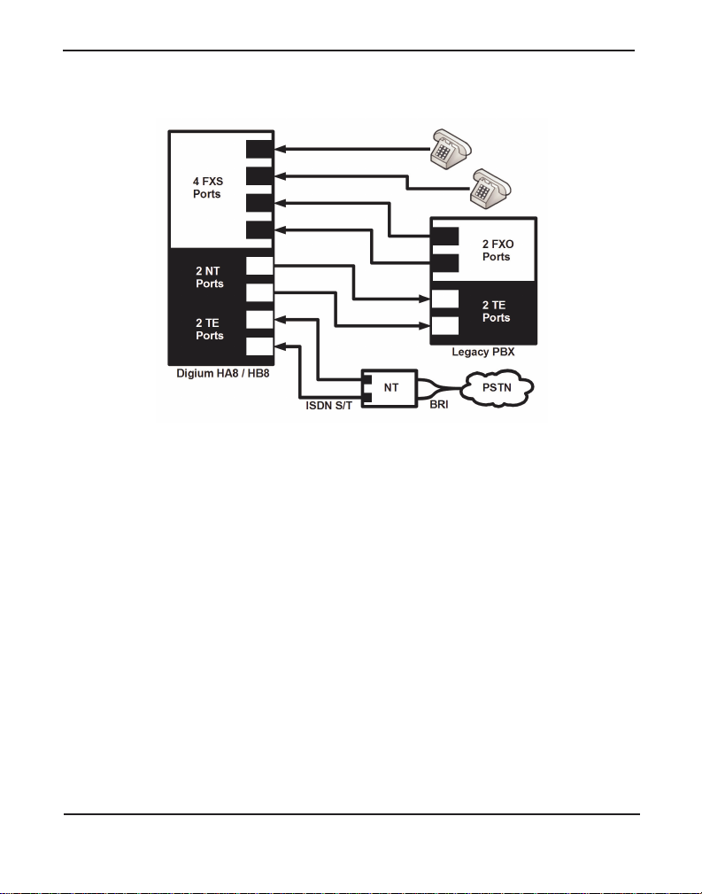
The Digium BRI module is compatible with Euro-ISDN. It is capable of
serving as a Terminal Equipment (TE) and/or Network Termination (NT)
device. When configured as an NT device, it is the source of BRI lines as
shown in Figure 1 and Figure 2.
Note: The Hx8 Series cards do not support North American BRI.
There are a variety of applications where the Hx8 Series cards (HA8 or
HB8) can prove useful. Examples are provided in the following figures.
Digiu m, In c . Page 17
Page 18
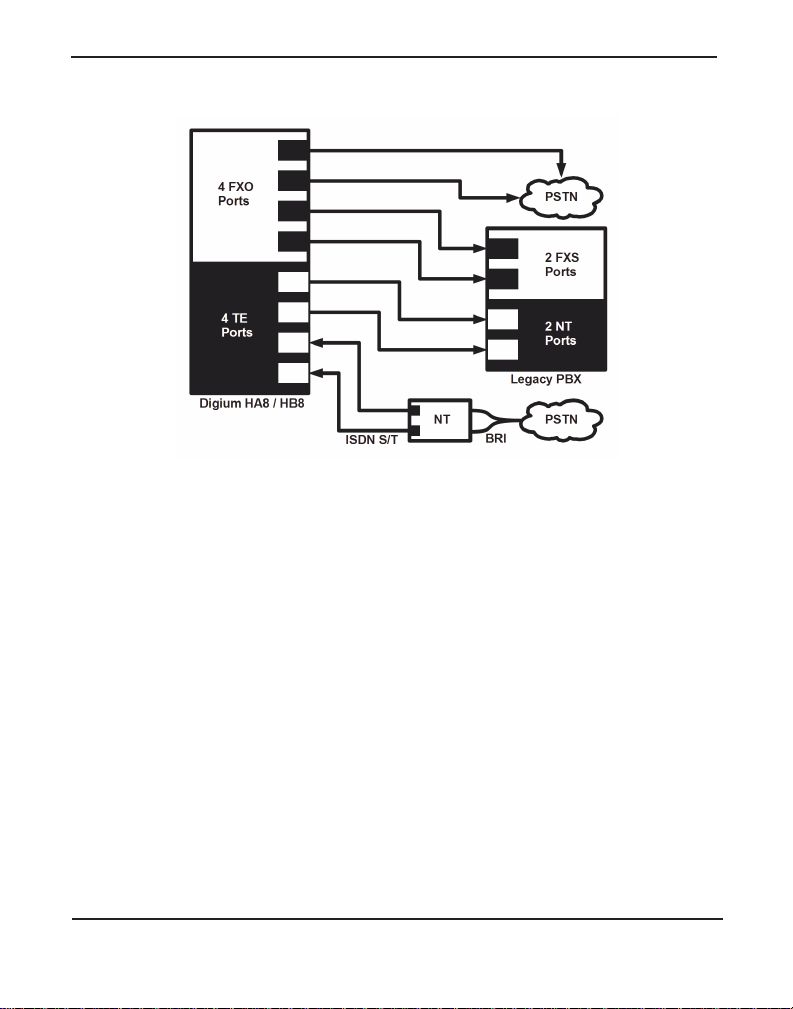
Chapter 1: Overview
Figure 1: Sample Card Application for FXO / BRI
Digium, Inc. Page 18
Page 19
Chapter 1: Overview
Figure 2: Sample Card Application for FXS / BRI
Digium, Inc. Page 19
Page 20

Chapter 1: Overview
Echo-Cancellation
Users connecting the ir Hx8 Series cards to the PSTN or other devices are
likely to be placing calls that will result, at some point, in an unbalanced
4-wire/2-wire hybrid. The result of this hybrid is the reflection of a nearend echo to the calling party. Elimination of this echo is th e responsibility
of echo cancellation.
The Hx8 Series cards, unless otherwise equipped, utilize Asterisk to
perform software-based echo cancellation. Asterisk maintains a number
of open source ech o can c el lers . The s e open s o urce ech o can ce l le rs
provide a moderate level of echo cancellation, but are not capable of
dealing with higher levels of, or more advanced, echoes.
Digium recommends that those users concerned about echo cancellation
purchase the VPMADT032 hardware echo cancellation module. The
VPMADT032 may be combined with both the HA8 and HB8.
The VPMADT032 is desi gned to h andle up to 128m s of e cho cance llati on
across all channels and provides a G.168 echo cancellation solution.
Digium, Inc. Page 20
Page 21

Chapter 1: Overview
What is Asterisk®?
Asterisk is th e world’s le ading open source telephony engine and tool kit.
Offering fle xibility unheard of in the world of proprietar y
communications, Asterisk empowers developers and integrators to create
advanced communication solutions...for free. Asterisk is r eleased as open
source under the GNU General Public License (GPL), and it is available
for download free of charge. Asterisk is the most popular open source
telephony software available, with the Aster isk Community being the top
influencer in VoIP.
Asterisk as a Phone Switch (PBX)
Asterisk can be configured as the core of an IP or hybrid PBX, switching
calls, managing routes, enabling features, and conne cting callers with the
outside world over IP, analog (POTS), and digital (T1/E1/J1/BRI)
connections.
Asterisk runs on a wide variety of opera ting systems including Linux,
Mac OS X, OpenBSD, FreeBSD, and Sun Solaris. It provides all of the
features you would exp ect from a PBX inclu ding many adva nced featu res
that are often associate d with high end (and high cost) proprietary PBXs.
Asterisk's archi tecture is designed for maximum flexibilit y and supports
Voice over IP in many protocols, and can interoperate with almost all
standards-base d telephony equipment using relatively inexpensive
hardware.
Asterisk as a Gateway
It can also be built out as the heart of a media gateway, bridging the
legacy PSTN to the expanding world of IP telephony. Asterisk’s modular
Digium, Inc. Page 21
Page 22

Chapter 1: Overview
architecture a llows it to co nvert between a wide ran ge of communicat ions
protocols and media codecs.
Asterisk as a Feature/Media Server
Need an IVR? Asterisk’s got you covered. How about a conference
bridge? Yep. It’s in there. What about an automated at tendant? Asterisk
does that too. How about a replacement for your agi ng legacy voicemail
system? Can do. Unified messaging? No problem. Need a telephony
interface for your web site? Okay.
Asterisk in the Call Center
Asterisk has been adopted by call centers around the world based on its
flexibility. Call center and contact center developers have built complete
ACD systems based on Asterisk. Asterisk has also added new life to
existing call center solutions by adding remote IP agent capabilities,
advanced skills-based routing, predictive and bulk dialing, and more.
Asterisk in the Network
Internet Telephony Service Providers (ITSPs), Competitive Local
Exchange Ca rri ers (C LEC s ) an d eve n first -t ier incu m b en ts hav e
discovered the power of open source communications with Asterisk.
Feature servers, hosted services clusters, voicemail systems, and pre-paid
calling solution s, a ll based on Asterisk have helped reduce costs and
enabled flexibility.
Digium, Inc. Page 22
Page 23

Chapter 1: Overview
Asterisk Everywhere
Asterisk has become the basis for thousands of communications
solutions. If you need to communicate, Asterisk is your answer. For more
information on Asteris k, visit http://www.asterisk.org or http://
www.digium.com.
Digium, Inc. Page 23
Page 24

Chapter 2 Card Installation
This chapter provides the following information:
Unpacking the Card on page 25
Shipmen t Ins pec ti o n on page 26
Module Identification on page 26
Port Identi fica ti on on page 27
Applying a Port Identifica tion Label on page 32
Card Identification on page 33
Slot Compatibility on page 37
Hardware Installat ion on page 39
Connecting a Timing Cable on page 43
FXO, FXS, and BRI Connection on page 44
Software Installation on page 45
Installing Asteris k on page 49
Note: The Hx8 Series card installation instructions are written so that
they will apply to any card in the series. Example s and card specific
information are included as needed.
Digiu m, In c . Pa g e 2 4
Page 25
Chapte r 2: C ar d In st a lla tion
Unpacking the Card
When you unpack your card, carefully inspect it for any damage that may
have occurred in shipment. If damage is suspected, file a claim with the
carrier and contact the reseller from which the card was purchased. If the
card was purchased direct from Digium, contact Digium Technical
Support at +1.256.428.6161. Keep the original shipping container to use
for future shipment or proof of damage during shipment.
Note: Only qualified service personnel should install the card. Users
should not attempt to perform thi s function themselves. The installer
must ensure that the equipment is permanently connected equipment,
pluggable type B or connecte d t o a socke t-outle t tha t has bee n checke d
to ensure that it is reliably earthed in accordance with the National
Electrica l Code.
This ca rd is in t en d e d fo r installatio n in a Restricted Access
Location (RAL) only.
Digium, Inc. Page 25
Page 26

Chapte r 2: C ar d In st a lla tion
Shipment Inspection
The following items are includ ed in shipment of an Hx8 Series card:
Hx8 Series card (HA8 or HB8)
FXO, FXS, and/or BRI module(s), depending on configuration
4 or 8 Digium BRI RJ11-to-RJ45 cable s for BRI configurations only
Port identification labels
Note: After inspecting the shipment, Digium highly recommends that
you register the card for support eligibility. Please refer to Free
Installation Support on page 89 for additional information on how to
obtain assistance from Digium Technical Support.
Module Identification
The Hx8 Series cards ship with FXO, FXS, and/or BRI modules in place.
These are identified by their color. Take a moment to identify which
modules were shipped with your card.
FXO (Foreign Exchange Office) modules are Red
FXS (Foreign Exchange Station) modules are Green
BRI (Basic Rate ISDN) modules are Blue
The Hx8 Series cards may also be combined with Digium’s hardwarebased echo canceller, model VPMADT032. See Figure 5 on page 30 for
an example of the HA8 card shown with the echo cancellation module.
Digium, Inc. Page 26
Page 27

Chapte r 2: C ar d In st a lla tion
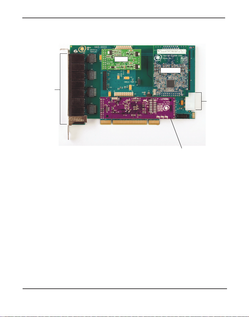
Port Identification
Each card consists of eight RJ11 ports located on the bracket. Each RJ11
port correlates to a single FXO or FXS channel, or to a single BRI span.
The ports are numbered in sequence from one to eight. The top port is
Port 1 and the bottom port is Port 8. See Figure 3 on page 28 for
appropriate ident ification of these ports. The port identif ication is the
same for all cards in this series.
It is important to identify the type and location of your Hx8 Series
modules. You will need this informat ion during the Asterisk
configuration.
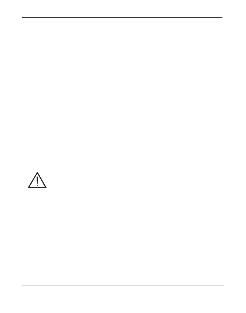
The ports available for use on the Hx8 Series cards are not continuous.
The ports available for use depend upon the type of module used, and the
placement of the module on the card. The cards can acce pt 2 quad
modules, for a total of 8 ports. If single modules are used, only 2 single
modules can occupy the same spac e as a quad module. The single module
ports are identifi ed on the card and the ir corresponding RJ11 ports a re
identified belo w . Please refer to Figur e 5 on page 30 for an example using
a single module, and Figure 6 on page 31 for an example using quad
modules.
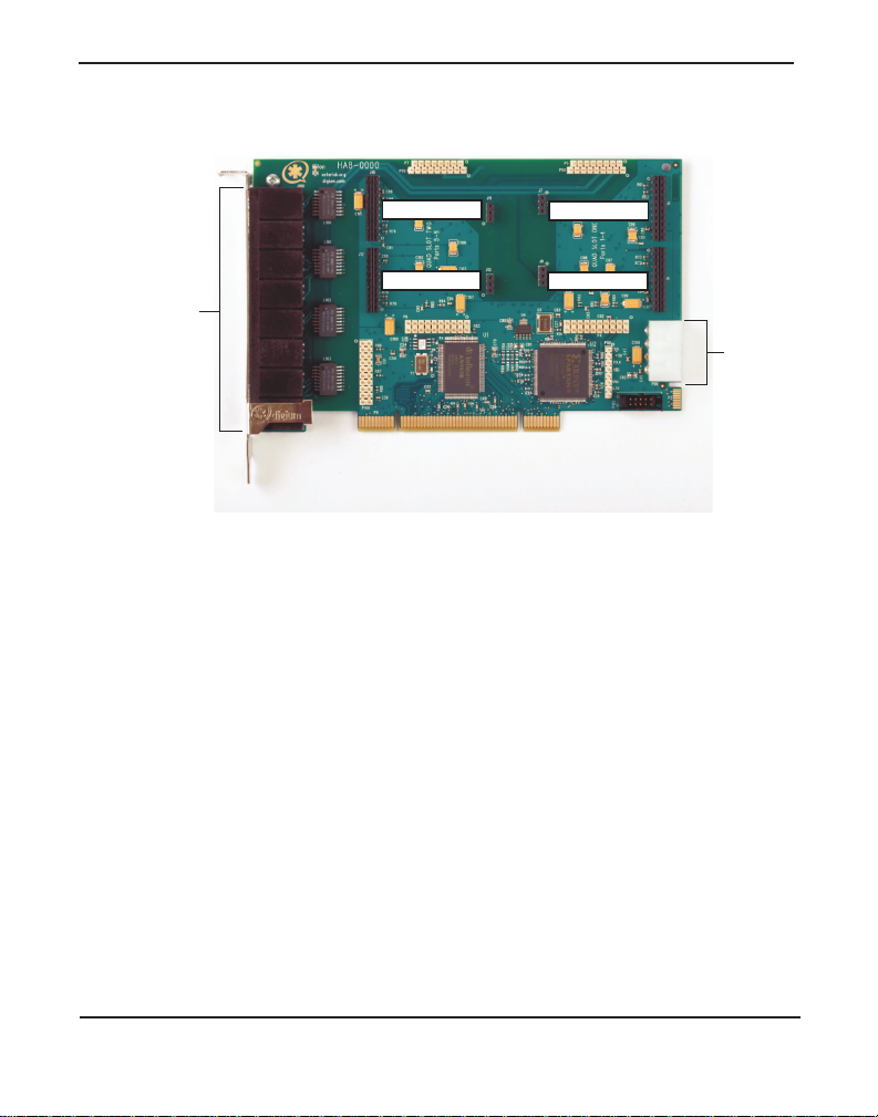
If a single module is used, the RJ11 port available for use will be the port
corresponding to the location of the module on the card. The following
ports correspond to the single module ports as shown in Figure 3.
RJ11 Port 1 is used by Single Module Port 1
RJ11 Port 2 is used by Single Module Port 2
RJ11 Port 5 is used by Single Module Port 5
RJ11 Port 6 is used by Single Module Port 6
Digium, Inc. Page 27
Page 28
Chapte r 2: C ar d In st a lla tion
8
Power
Supply
Single Port 1
Single Port 2
Single Port 5
Single Port 6
Ports
1 (top)
through
8 (bottom)
Figure 3: HA8 Base Card with Single Port Identification
Digium, Inc. Page 28
Page 29
Chapte r 2: C ar d In st a lla tion
8
Power
Supply
Ports
1 (top)
through
8 (bottom)
Quad Slot 1, Ports 1-4
Quad Slot 2, Ports 5-8
Figure 4: HA8 Base Card with Quad Port Identification
Digium, Inc. Page 29
Page 30
Chapte r 2: C ar d In st a lla tion
Power
Supply
Ports
1 (top)
through
8 (bottom)
VPMADT032 Echo
Cancellation Module
Ports 1-4
Port 5
Digium, Inc. Page 30
Figure 5: HA8 Bundle with Single Module and Quad Module
Page 31

Chapte r 2: C ar d In st a lla tion
Power
Supply
Ports
1 (top)
through
8 (bottom)
VPMADT032 Echo
Cancellation Module
Ports 1-4
Ports 5-8
If a quad module is placed cover ing single module ports 1 a nd 2, then that
module will use ports 1-4. Likewise, if a quad module is placed covering
single module ports 5 and 6, the module will use ports 5 through 8.
Figure 6 shows a HA8 card with two quad modules.
Digium, Inc. Page 31
Figure 6: HA8 Bundle with 2 Quad Modules
Page 32
Chapte r 2: C ar d In st a lla tion
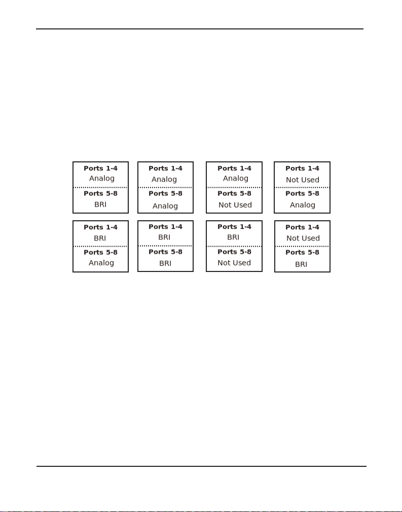
Applying a Port Identification Label
Once you have identified the ports of the Hx8 Series card, you should
apply a port identification label. This is important in order to ensure that
only compatible devices ar e connecte d to the ports o f t he Hx8 Serie s card.
It is highly recommended that you apply the label in a clearly visible
location near the external port connectors.
Figure 7: Example Port Identification Labels
Note: The port identifica t ion la be ls pack aged with an Hx8 Se ries
card may differ from this example.
Digium, Inc. Page 32
Page 33
Chapte r 2: C ar d In st a lla tion
Card Identification
There are multiple config urations in which an Hx8 Series card may be
purchased. Each configuration consists of a combination of single
modules, quad modules, or both, and may also include the VPMADT032
echo cancellation modul e. See Table 1 on page 33 for a list of the most
common HA8 configurations. See Table 2 on page 35 for a list of the
most common HB8 configurations. The lists are not complete, but rather
an example of some of the configurations available.
It is easie st to identify your c ard by understanding the naming scheme for
each card. The first digit is the maximum port count of the card. The
second digit is reserved fo r futur e use. The third digit is the number of
BRI ports present on the card. The fourth digit is the number of FXS ports
present on the card. The fifth digit is the number of FXO ports present on
the card. An “S” in p lace of t he fou rth digi t si gnifie s the use of single FXS
modules. An “S” in place of the fif th digit signifies the use of single FXO
modules. A “B” at the end signifies the use of a hardware echo
cancellation module.
Table 1: Example HA8 Bundles
Card ID Ports
HA8-0001 1 Single FXO module without hardware echo
cancellation
HA8-00S4 4 Single FXO modules without hardware echo
cancellation
HA8-0004 1 Quad FXO module without hardware echo
cancellation
Digium, Inc. Page 33
Page 34

Chapte r 2: C ar d In st a lla tion
Table 1: Example HA8 Bundl es (continued)
Card ID Ports
HA8-0008B 2 Quad FXO modules with hardware echo
cancellation
HA8-0010 1 Single FXS module without hardware echo
cancellation
HA8-004S 4 Single FXS modules without hardware echo
cancellation
HA8-0040 1 Quad FXS module without hardware echo
cancellation
HA8-0080B 2 Quad FXS modules with hardware echo
cancellation
HA8-0044B 1 Quad FXS and 1 Quad FXO module wi th hardware
echo cancellation
HA8-0400B 1 BRI module with hardware echo cancellation
HA8-0800B 2 BRI modules with hardware echo cancellation
HA8-0440B 1 BRI and 1 Quad FXS module with hardware echo
cancellation
Digium, Inc. Page 34
Page 35

Chapte r 2: C ar d In st a lla tion
Table 2: Example HB8 Bundles
Card ID Ports
HB8-0001 1 Single FXO module without hardware echo
cancellation
HB8-00S4 4 Single FXO modules without hardware echo
cancellation
HB8-0004 1 Quad FXO module without hardware echo
cancellation
HB8-0008B 2 Quad FXO modules with hardware echo
cancellation
HB8-0010 1 Single FXS module without hardware echo
cancellation
HB8-004S 4 Single FXS modules without hardware echo
cancellation
HB8-0040 1 Quad FXS module without hardware echo
cancellation
HB8-0080B 2 Quad FXS modules with hardware echo
cancellation
HB8-0044B 1 Quad FXS and 1 Quad FXO module with hardware
echo cancellation
HB8-0400B 1 BRI module with hardware echo cancella tion
Digium, Inc. Page 35
Page 36

Chapte r 2: C ar d In st a lla tion
Table 2: Example HB8 Bundles (continued)
Card ID Ports
HB8-0800B 2 BRI modules with hardware echo cancella tion
HB8-0440B 1 BRI and 1 Quad FXS module with hardware echo
cancellation
Caution
Only qualified service personnel should continue with
hardwa r e i nstal lat ion and c onfi gurat ion o f the Hx8 Seri es card.
Users should not at tempt to perf orm t hese f unct ions th emselve s.
Digium, Inc. Page 36
Page 37

Chapte r 2: C ar d In st a lla tion
Slot Compatibility
Check the slots on your motherboard to veri fy that you have a slot
available w hic h is com p atibl e w ith the Hx8 Seri es card s. To determine
which slots you have on your motherboard, identify them by comparing
them to those shown in Figure 8.
Slot Number:
0: AGP Pro Slot
1: 64-bit 5.0 volt PCI Slot
2: 64-bit 3.3 volt PCI Slot
3: 32-bit 5.0 volt PCI Slot
4: PCI Express 1-lane (x1) Slot
5: PCI Express 4-lane (x4) Slot
6: PCI Express 8-lane (x8) Slot
7: PCI Express 16-lane (x16) Slot
Figure 8: Motherboard Slots
Digium, Inc. Page 37
Page 38

Chapte r 2: C ar d In st a lla tion
The HA8 card is a 32-bit 33 MHz card ke ye d for universal 3.3 volt or 5.0
volt operation and works in any PCI 2.2 (or greater) compliant slot. This
means that in the motherboard shown in Figur e 8, the HA8 card will fit
into Slots 1, 2, or 3 (PCI slots), but cannot fit into any of the other slots.
The HB8 card is keyed f or a PCI Expre ss 1-la ne (x1) sl ot and will work in
any PCIe revision 1.0 compliant slot, including lane lengths x4, x8, and
x16. This means that in the motherboard shown in Figure 8, the HB8 card
will fit into Slots 4, 5, 6, or 7 (PCI Express), but cannot fit into any of the
other slots.
Digium, Inc. Page 38
Page 39
Chapte r 2: C ar d In st a lla tion
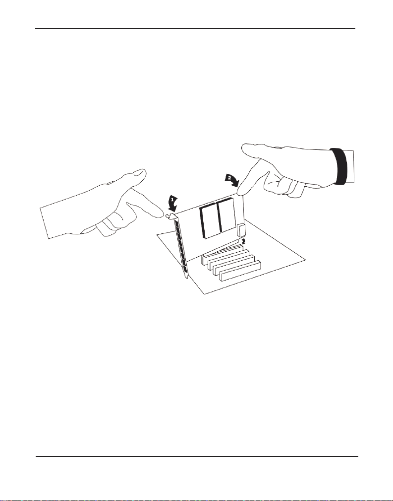
Hardware Installat ion
1. Now that you are acquainted with your card, power down your com-
puter , a nd unplug it from its power source.
2. Attach an anti-static strap to your wrist and open the case.
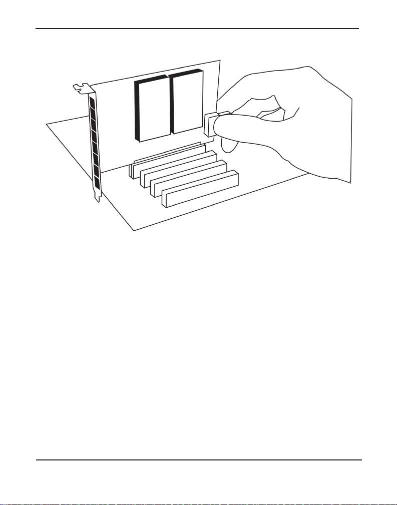
3. Remove the bracket plac e holde r and insert the card into a PCI (HA8)
or PCI Express (HB8) slot. See Figure 9.
Figure 9: Insert the Card
4. If your card has any FXS modules, you will also need to connect the
power cable from your computer’s power supply to the back of the
card. Insert a four-pin 12 volt connector (disk drive power supply
cable, e.g. hard drive) into the white plastic connector on the rear of
the card. See Figure 10.
Digium, Inc. Page 39
Page 40
Chapte r 2: C ar d In st a lla tion
Figure 10: Connect Power for FXS Modules
Many modern PCs and servers do not have either spa re or any 12V power
connectors. If you have FXS modules on your card and your compute r
does not have power cables available , then power must be provided to the
Hx8 Series card by an alternate means. Digium provides a solution to this
issue with the optional PWR2400B (availa ble separately). The
PWR2400B card is essentially a PCI bracket assembly that takes power
from an external DC power supply and routes it to two 15" power cabl es
inside the computer. You must have an available bracket slot to use the
PWR2400B (either PCI, PCI Express or AGP).
A strap on the PWR2400B card allows the two power cables to take
power from the same DC s upply. The PWR2400B comes with one power
supply capable of supporting up to 24 FXS ports, driving heavy loads of
up to 5REN per port. If more than 24 FXS ports with heavy loads are
connected to the PWR2400B, then a second Digium power supply should
Digium, Inc. Page 40
Page 41
Chapte r 2: C ar d In st a lla tion
be purchased. The shorti ng strap on the PWR2400B should be removed if
a second power supply is used.
The PWR2400B does not connect to any bus inside the computer. It may
be used where ver there is an available PC I-s i ze brac ket such as a PCI,
PCI Express, or AGP slot.
Note: The PWR2400B is not intended to supply power to any other
device, it is intended only to be used with UL Listed Digium analogcapable cards.
5. Replace the cover to your computer.
Electrical Shock
To re duce the risk of injury, damage to the unit or your
equipment, do not attempt to apply power to the unit while the
case is open. Pe rsonal injury or damage to the unit could occur
if the modules are touched while powered is applied.
6. Plug all analog telephone lines to the FXO (red) ports and all analog
phones to the FXS (green) ports as needed using a pa tch panel, punch
block, or standard RJ11 telephone cables. Then plug all BRI lines to
the BRI (blue) port s using a patc h panel , punch bl ock, or the pr ovided
Digium BRI RJ11-t o-RJ45 cables. Refer to the pin assignments
starting on page 90.
Caution
This unit must be connected to the Telecommu nications
Network in your country using an approved line cord, e.g. : for
Australia use only line cords complying with ACA Technical
Standard TS008.
Digium, Inc. Page 41
Page 42

Chapte r 2: C ar d In st a lla tion
Caution
Only connect regulatory equipment (approved for use in your
specific country) to the telecommunications network voltage
circuit ports.
Digium, Inc. Page 42
Page 43

Chapte r 2: C ar d In st a lla tion
Connecting a Timing Cable
The timing por t allow s u p to three Hx 8 Seri es cards to sha re the sam e
sync (timing) source from the BRI line provider, or provide a consistent
sync source across multipl e cards. This is a useful feature for fax modes
and some voice applications to prevent corruption due to timing slips on
the second and third Hx8 Series cards .
To utilize this feature, daisy-chain the P102 connector between each Hx8
Series card using the Digium 3-posi tion, 10-pin timing cable. Enable this
feature by using the
timingcable=1 kernel module parameter when the
driver is lo aded:
# modprobe wctdm24xxp timingcable=1
Figure 11: Timing Cable Connection
Digium, Inc. Page 43
Page 44

Chapte r 2: C ar d In st a lla tion
FXO, FXS, and BRI Connection
The Hx8 Series cards provide eight RJ11 connectors for access to the
FXS, FXO, and BRI modules installed in the available slots. Using a
standard RJ1 1 telephone cable, an analog telephone line should be
plugged into one of the RJ11 connectors associated with an FXO module
on the Hx8 Seri es card. Using a standard RJ11 te lephone cable, an an alog
phone should be plugged into one of the RJ11 connectors associated with
an FXS module on the Hx8 Series card. Using a Digium BRI RJ11-toRJ45 cable, a digital BRI line should be plugged into one of the RJ11
connectors assoc iated with a BRI m odule on t he Hx8 Ser ies ca rd. Refe r to
the pin assignments start ing on page 90.
Digium, Inc. Page 44
Page 45

Chapte r 2: C ar d In st a lla tion
Softw a r e In s t al la t io n
Digium hardware requires driver s and libraries that are not integrated
with the Linux kernel. Digium hardware is only supported under Linux.
Digium recommends CentOS, Debian, R ed Hat, and Ubuntu distribut ions
of Linux. However, many other distributions are supported by Digium
Technical Support.
Digium’s software, including drivers and application software, may be
obtained from Digium’s download servers at:
http://downloads.digium.com
http://downloads.asterisk.org
For an introduction to Asterisk, Digium’s telephony software, including
additional infor mation on its configuration, setup, and features, please
refer to:
http://www.asterisk.org
For the latest information on se tting up and configuring DAHDI drivers
for your Digium hardwar e product, please refer to t he lat est relea se of t his
manual which is available fro m the product-specific documentation
section at:
http://www.digium.com
T o install your Hx8 Series card, you will need:
Linux 2.6 kernel headers
Development librarie s and head ers for ncurses
Development librarie s and head ers for zlib and openssl
Development librarie s and headers for newt
GCC and standard software build tool s
Digium, Inc. Page 45
Page 46

Chapte r 2: C ar d In st a lla tion
It is recommended that you use the most recent version of the Asterisk,
DAHDI, and libpri software for the best results. If you have previously
installed any of these, Digium recommends that you upgrade to the latest
“-current” version of each.
Note: The Hx8 Series cards’ minimum version requirements are
Asterisk 1.6.0.1, DAHDI Linux 2.3.0, DAHDI Tools 2.3.0, and libpri
1.4.10.2.
1. After the machine has booted to Linux, log in and execute the follow-
ing command to list the devices detected by the PCI bus:
# lspci -n
Confirm that the output from lspci lists a device with Digium’s PCI
vendor ID which is “d161”. The screen output should be simila r to the
following:
00:0a.0 0200: d161:<card identifier> (rev 01)
Note: The output from lspci may or may not state “Unknown
device”. If it does, this does not indicate a problem.
In the PCI device listing shown above, <card identifier> will be
populated with one of the identifiers listed in the table below.
Digium, Inc. Page 46
Page 47

Chapte r 2: C ar d In st a lla tion
Table 3: Card Identifiers
Model Identifier
HA8
HB8
8007
8008
A Digium Hx8 Series (HA8/HB8) card ide ntifier should be listed. If a
matching card identifier is not listed, then your machine is not PCI 2.2
(or higher) or PCI Express compatible , and the card wil l not work wi th
your motherboard.
2. Download the latest versio n of libpri. Substitute the version of libpri
for the X.X in the command line below. libpri is available for
download from:
http://downloads.asterisk.org/pub/telephony/libpri
# wget http://downloads.asterisk.org/pub/telephony/
libpri/libpri-X.X-current.tar.gz
Note: There is no coorelation between the versioning of libpri and
Asterisk. The libpri 1.4 br anch will function with the Asterisk 1.6
branch.
3. Expand the dow nl oad ed file , compile its contents , and insta l l the
libraries. Substitute the version of libpri for the X.X and X.X.X.X in
Digium, Inc. Page 47
Page 48

Chapte r 2: C ar d In st a lla tion
the command lines below.
# tar -zxvf libpri-X.X-current.tar.gz
# cd libpri-X.X.X.X/
# make
# make install
4. Download the latest DAHDI drivers with tools. DAHDI is available
for download from:
http://downloads.asterisk.org/pub/telephony/dahdi-linux-complete
# wget http://downloads.asterisk.org/pub/telephony/
dahdi-linux-complete/dahdi-linux-completecurrent.tar.gz
5. Expand the dow nl oad ed file , compile its contents , and insta l l the
drivers and tools. Substitute the version of DAHDI for the X.X.X in
the command lines below.
# tar -zxvf dahdi-linux-complete-current.tar.gz
# cd dahdi-linux-complete-X.X.X+X.X.X
# make
# make install
# make config
Note: Executing ‘make config’ will install an init script and symlinks
which will allow you to start and stop DAHDI as a service.
Digium, Inc. Page 48
Page 49

Chapte r 2: C ar d In st a lla tion
Installing Asteris k
If you wish to use Asterisk with your new hardware, you can follow the
instructions below.
1. Download the latest relea se version of Asterisk 1.6 or later. Substitute
the version of Ast erisk for the X.X.X in the command be low. Asterisk
is available for download from:
http://downloads.asterisk.org/pub/telephony/asterisk
# wget http://downloads.asterisk.org/pub/telephony/
asterisk/asterisk-X.X.X-current.tar.gz
2. Expand the dow nl oad ed file , compile its contents , and insta l l the
application. Substitute the version of Asterisk for the X.X.X and
X.X.X.X in the command lines below.
# tar -zxvf asterisk-X.X.X-current.tar.gz
# cd asterisk-X.X.X.X/
# ./configure
# make menuselect
# make
# make install
Digium, Inc. Page 49
Page 50

Chapte r 2: C ar d In st a lla tion
3. If this i s the fir st Aste risk i nstall at ion on th is s ystem, you sho uld install
the sample configurati on files. To do this, run:
# make samples
Note: Running this command will overwrite, after making a backup
copy, any older Asterisk configura tion files that you have in the
/etc/asterisk dir ectory.
If your installation has failed, it may be because you are missing one
or more of the build dependencies, the kerne l headers, or the
development tools. Contact your reseller where the card was
purchased, or call Digium Technica l Support at +1.256.428.6161 for
assistance. Please refer to F ree Ins ta llati o n Supp o rt on page 89 for
additional infor mation on how to obtain assistance from Digium
Technical Support.
Complete instructi ons for installing Asterisk are available at
www.asterisk.org
.
Digium, Inc. Page 50
Page 51

Chapter 3 Configuration
The Hx8 Series cards have a variety of configuration options. This
chapter provides sample configurations to demonstrate customi zing the
Asterisk software to meet your individual needs. Each section explains
basic options as examples. Once you have familiarized yourself with the
samples, you can edit the configura tion files to meet your specific needs.
Digiu m, In c . Pa g e 5 1
Page 52

Chapter 3: Configuration
Understanding Span and Channel Assignments
In order to properly configure your Hx8 Series card, it is important to
understand how spans and channels are assigne d to the card in software.
A span is a group of channels that is bundled togeth er in sof t ware .
Depending on how an Hx8 Series card is configured , it can have one
analog span, four digi tal spans, eight digit al spa ns, or one analo g span a nd
four digital spans. The following bulleted lists provide important
information regard ing analog and digital spans.
Analog Span for FXO/FXS
– The analog span will not exist if there are no analog modules
installed.
– The assignment of the analog span alw ays co mes aft er the as sign -
ment of the digital span.
– The analog span always has 8 channels allocated, regardless of the
number of FXO and/or FXS modules that are installed.
– A single implied span exists for all populated and unpopulated ana-
log ports.
– Unpopulated analog ports occupy exactly 1 channel and go into the
analog span.
– As far as the analog span is concerned, BRI ports allocated by a BRI
module are unpopulated ports.
Note: This is extremely important to know when determining the
channel assignment of your analog module(s) when a BRI module
is installed in the first quad port (non-standard configuration).
Digium, Inc. Page 52
Page 53

Chapter 3: Configuration
Digital Spans for BRI
– A digital span will not exist if there are no BRI modules installed.
– The assignment of a digital span always comes before the assign-
ment of an analog span.
– Four digital spans are dynamically created for each BRI module on
the card (0, 4, or 8 total spans).
– Digital spans always consist of 2 bchans (i.e. B Channels) and 1
hardhdlc channel (i.e. D Channel). The channels are allocated in
that order.
Digium, Inc. Page 53
Page 54

Chapter 3: Configuration
Driver Configuration
You should ha ve id entifie d the t ype of Hx8 Seri es car d when you rece ived
it. If you are not sure, refer to Module Identification on page 26 for
assistance.
1. Begin by opening the system.conf file from the
/etc/dahdi directory.
2. Specify the two lett er country c ode for your loa dzone and defaultz one.
This will preload tone zone data and specif y a def ault tone zone for
your interfaces.
The following is a typical setup for a telco in the United States:
loadzone = us
defaultzone = us
The following is a typical setup for a telco in Spain:
loadzone = es
defaultzone = es
Digium, Inc. Page 54
Page 55

Chapter 3: Configuration
3. If your card has a blue BRI module, you will need to specify span
maps, bchans (i.e. B Channels), a nd hardhdlc chans (D Channels)
allocate d to it in the system.conf file.
First, configure the span map for each BRI line. The span map
includes defining the span number, timing, line build out, framing,
and coding. Configuration details for each of these items i s explained
in this section.
span => <Number>,<Timing>,<Line Build
Out>,<Framing>,<Coding>[,Yellow][,TE|,NT][,Term]
Number:
This is the port that the BRI line is plugged into. P ort 1 is the furthest
span from the PCI connector. The port numbers are noted on the PCI
bracket.
Timing:
This determines how timing is handle d by the spans.
0 - Span provides its own timing (master clock)
1 - Receives timing from remote end (slave clock)
2 - Receives secondary backup timing from remote end (slave clock)
3 - Receives tertiary backup timing from remote end (slave clock)
4 - Receives quaternary backup timing from remote end (sla ve clock)
... and so on.
Note: Only one span per card can be defined to tak e timing, and that
Digium, Inc. Page 55
Page 56

Chapter 3: Configuration
defines timing for the rest of the card’s spans. A setting of 0 should
always be used when in NT mode.
Line Build Out:
For most setups the line build out is 0.
0: 0 db (CSU) / 0-133 feet (DSX-1)
1: 133-266 feet (DSX-1)
2: 266-399 feet (DSX-1)
3: 399-533 feet (DSX-1)
4: 533-655 feet (DSX-1)
5: -7.5db (CSU )
6: -15db (CSU)
7: -22.5db (CSU)
Framing:
BRI utilizes CCS framing.
Coding:
BRI utilizes AMI coding.
Yellow:
The optional yellow flag can be added at the end for transmitting a
yellow alarm when no channels are open. For example, a yellow
alarm will be transmitted when DAHDI is configured and initialized,
but Asterisk is not running. Sending a yellow alarm is useful for the
local side to notify the remote side that it is not ready to accept calls,
and for determining which direction a communication problem exists
Digium, Inc. Page 56
Page 57

Chapter 3: Configuration
during troubleshooting. If this setting is unspecifie d and Aster isk is
not running, DAHDI will not report an al arm and the remote side will
think that the local sid e is ready to acc ep t calls .
TE or NT:
Each of the BRI ports can be set for TE or NT mode independently.
Specify TE to act as Terminal Equipment, or NT act as a Network
Termination device. The default setting is TE mode.
There is a risk of electrical shock due to lightning when this
device is utili zed in TE mode. Take safety pr ecautions when
using the card in this man n er.
Term (Termination):
Any BRI port can use 100 ohm termina tion. This s hould be enabl ed if
the placement of an Hx8 Series card is the last in a daisy-chain. This
is always the case when using PTP mode, and sometimes the case
when using PTMP mode. Termination should be disabled only in
instances where an Hx8 Series card’s placement is inside of a daisychain. This is never the case when using PTP mode, and sometimes
the case when using PTMP mo de. Th e default sett ing is off . Exa mples
are provided below.
NT (Term) <----> TE PTP (Term)
NT (Term) <----> TE PTMP (Term)
NT (Term) <----> TE PTMP (No Term) <----> TE PTMP (Term)
Digium, Inc. Page 57
Page 58

Chapter 3: Configuration
Note: If t ermina tion is n ot se t app ropriately, the D-Channel(s) may no t
remain stable.
Digium, Inc. Page 58
Page 59

Chapter 3: Configuration
Table 4: Common BRI Span Configur ations
Mode Card Position Span Line
TE Point-to-Point last in daisy-c hain span => 1,1,0,ccs,a mi ,te,term
TE Point-to-Multipoint last in daisy-c hain span => 1,1,0,ccs ,ami,te,term
TE Point-to-Multipoint inside daisy-c hain span => 1,1,0,ccs,ami,te
NT Point-to-Point last in daisy-c hain span => 1,0,0,ccs,a mi ,nt,term
The following is a typic al span map setup when connecting to a telco
in Europe:
span => 1,1,0,ccs,ami,te,term
span => 2,2,0,ccs,ami,te,term
span => 3,3,0,ccs,ami,te,term
span => 4,4,0,ccs,ami,te,term
Then you will need to specify the channel definitions for each span.
The channel definition format is:
<device> = <channel list>
A list of valid devices are specified in the sample system.conf file.
The devices that need to be specified for a BRI module are listed
below.
bchan = 1,2,4,5,7,8,10,11
hardhdlc = 3,6,9,12
Digium, Inc. Page 59
Page 60

Chapter 3: Configuration
The bchan device specifies the beare r channels (B channels). The
hardhdlc device specifies the delta channel (D channel).
Note: Unlike Digium’s Digital T1/E1 car ds, the device for the delta
channel must be specified as hardhdlc instead of dchan. The Hx8
Series cards will not function properly if dchan is specified.
The combined configurati on should look like the following:
loadzone = es
defaultzone = es
span => 1,1,0,ccs,ami,te,term
bchan = 1,2
hardhdlc = 3
span => 2,2,0,ccs,ami,te,term
bchan = 4,5
hardhdlc = 6
span => 3,3,0,ccs,ami,te,term
bchan = 7,8
hardhdlc = 9
span => 4,4,0,ccs,ami,te,term
bchan = 10,11
hardhdlc = 12
If your card has two BRI modules installed, the configuration should
Digium, Inc. Page 60
Page 61

be specified as the following:
loadzone = es
defaultzone = es
span => 1,1,0,ccs,ami,te,term
bchan = 1,2
hardhdlc = 3
span => 2,2,0,ccs,ami,te,term
bchan = 4,5
hardhdlc = 6
span => 3,3,0,ccs,ami,te,term
bchan = 7,8
hardhdlc = 9
span => 4,4,0,ccs,ami,te,term
bchan = 10,11
hardhdlc = 12
Chapter 3: Configuration
span => 5,1,0,ccs,ami,te,term
bchan = 13,14
hardhdlc = 15
span => 6,2,0,ccs,ami,te,term
bchan = 16,17
hardhdlc = 18
span => 7,3,0,ccs,ami,te,term
bchan = 19,20
Digium, Inc. Page 61
Page 62

hardhdlc = 21
span => 8,4,0,ccs,ami,te,term
bchan = 22,23
hardhdlc = 24
Chapter 3: Configuration
Digium, Inc. Page 62
Page 63

Chapter 3: Configuration
4. If your card has a red quad FXO module, add the channel definitions
for it to the system.conf file.
The channel definition format is:
<device> = <channel list>
A list of valid devices are specified in the sample system.conf file.
The device that needs to be specified for an FXO module is listed
below.
fxsks =
fxsks uses kewlstart signa lling, which is loopstart signalling with
disconnect supervision. For example, an Hx8 Series cards with only a
quad FXO module installed would be configur ed as the following:
fxsks = 1-4
OR
fxsks = 1,2,3,4
If two quad FXO modules are installed, the configuration should be
specified as the follo wi n g:
fxsks = 1-8
OR
Digium, Inc. Page 63
Page 64

Chapter 3: Configuration
fxsks = 1,2,3,4,5,6,7,8
Note: The Hx8 Series cards do not support Ground Start signaling.
Note: An FXO module cannot be used in combination with a BRI
module that is taking timing in TE mode on the same Hx8 Series card.
An FXO module can be used in comb ination with a BRI modul e tha t is
providing timing in NT mode on the same Hx8 Series card.
If a quad FXO module is installed on the first quad slot, and a BRI
module is installed on the second quad slot, the configuration should
be specified as the following:
loadzone=es
defaultzone=es
span => 1,0,0,ccs,ami,nt,term
bchan = 1,2
hardhdlc = 3
span => 2,0,0,ccs,ami,nt,term
bchan = 4,5
hardhdlc = 6
span => 3,0,0,ccs,ami,nt,term
bchan = 7,8
hardhdlc = 9
Digium, Inc. Page 64
Page 65

Chapter 3: Configuration
span => 4,0,0,ccs,ami,nt,term
bchan = 10,11
hardhdlc = 12
fxsks = 13-16
Note: The analog span begins at channel 13 instead of 1 because the
assignment of an digita l spans always comes before the assignment of
an analog span. Please refer to the Understanding Span and Channel
Assignments section f or more details .
If a BRI module is installed on the first quad slot, a nd a quad FXO
module is installed on the second quad slot, the configuration should
be specified as the following:
loadzone=es
defaultzone=es
span => 1,0,0,ccs,ami,nt,term
bchan = 1,2
hardhdlc = 3
span => 2,0,0,ccs,ami,nt,term
bchan = 4,5
hardhdlc = 6
Digium, Inc. Page 65
Page 66

Chapter 3: Configuration
span => 3,0,0,ccs,ami,nt,term
bchan = 7,8
hardhdlc = 9
span => 4,0,0,ccs,ami,nt,term
bchan = 10,11
hardhdlc = 12
fxsks = 17-20
Note: The first four channels of the analog span (i.e. 13-16) are
unallocated becuase the BRI module is installed on the first quad slot.
As far as the analog span is concerned, BRI ports allocated by a BRI
module are unpopulated ports. Please refer to the Understanding
Span and Cha n nel A ssig nm e nt s section for more details.
Digium, Inc. Page 66
Page 67

Chapter 3: Configuration
5. If your card has a green quad FXS module, add the channel
definitions for it to the system.conf file .
The channel definition format is:
<device> = <channel list>
A list of valid devices are specified in the sample system.conf file.
The device that needs to be specified for an FXS module is listed
below.
fxoks =
fxoks uses kewlstart signa lling, which is loopstart signalling with
disconnect supervision. For example, an Hx8 Series cards with only a
quad FXS module installed would be configu red as the following:
fxoks = 1-4
OR
fxoks = 1,2,3,4
If two quad FXS modules are installed, the configuration should be
specified as the follo wi n g:
fxoks = 1-8
OR
Digium, Inc. Page 67
Page 68

Chapter 3: Configuration
fxoks = 1,2,3,4,5,6,7,8
Note: The Hx8 Series cards do not support Ground Start signaling.
If a quad FXS module is installed on the first quad slot, a nd a BRI
module is installed on the second quad slot, the configuration should
be specified as the following:
loadzone=es
defaultzone=es
span => 1,1,0,ccs,ami,te,term
bchan = 1,2
hardhdlc = 3
span => 2,2,0,ccs,ami,te,term
bchan = 4,5
hardhdlc = 6
span => 3,3,0,ccs,ami,te,term
bchan = 7,8
hardhdlc = 9
span => 4,4,0,ccs,ami,te,term
bchan = 10,11
hardhdlc = 12
fxoks = 13-16
Note: The analog span begins at channel 13 instead of 1 because the
Digium, Inc. Page 68
Page 69

Chapter 3: Configuration
assignment of an digita l spans always comes before the assignment of
an analog span. Please refer to the Understanding Span and Channel
Assignments section f or more details .
If a BRI module is installed on the first quad slot, a nd a quad FXS
module is installed on the second quad slot, the configuration should
be specified as the following:
loadzone=es
defaultzone=es
span => 1,1,0,ccs,ami,te,term
bchan = 1,2
hardhdlc = 3
span => 2,2,0,ccs,ami,te,term
bchan = 4,5
hardhdlc = 6
span => 3,3,0,ccs,ami,te,term
bchan = 7,8
hardhdlc = 9
span => 4,4,0,ccs,ami,te,term
bchan = 10,11
hardhdlc = 12
fxoks = 17-20
Note: The first four channels of the analog span (i.e. 13-16) are
Digium, Inc. Page 69
Page 70

Chapter 3: Configuration
unallocated becuase the BRI module is installed on the first quad slot.
As far as the analog span is concerned, BRI ports allocated by a BRI
module are unpopulated ports. Please refer to the Understanding
Span and Cha n nel A ssig nm e nt s section for more details.
Digium, Inc. Page 70
Page 71

Chapter 3: Configuration
6. DAHDI uses modular echo cancellers that are configured per channel.
The echo cancellers are compiled and installed as part of the dahdilinux package. You can specify the echo canceller to be used for each
channel. If a hardware echo cancel lation is not installed, the default
behavior is for there to be no echo canceller on any channel. So, it is
very important that you speci fy one in the system.conf file if you do
not have hardware echo cancellers and need echo cancellation. The
format is:
echocanceller = <echocanceller name>,<channel(s)>
A list of valid echo cancellers are specified in the sample system.conf
file.
The following is a typical setup using software-based echo
cancellation:
echocanceller = mg2,1-8
Note: If a hardwa re echo-cance llati on module is inst alled , please refer
to Configuring Card Features on page 73 for information on
configuring it.
Digium, Inc. Page 71
Page 72

Chapter 3: Configuration
7. Load DAHDI drivers into the kernel using the modprobe utility. The
appropriate driver for the Hx8 Series cards is
wctdm24xxp. Users
should use the following modprobe command:
# modprobe wctdm24xxp
# dahdi_cfg -vv
Note: The Hx8 Series cards use the same driv er as the TDM2400.
Digium, Inc. Page 72
Page 73

Chapter 3: Configuration
Configuring Card Features
You will need to modify the chan_dahdi.conf f ile which is located in the
/etc/asterisk directory in order to configure the essential features of your
card. This file is the configuration layer between DAHDI and Asterisk.
The signalling option will need to be set according to the type of module
that you have installed and the line that you will be connecting to it. The
following is a list of the most c ommonly used signalling types for an Hx8
Series card.
Table 5: Common Signalling Types
Signalling Description Module Mode
bri_cpe BRI CPE side using Point-to-
BRI TE
Point
bri_cpe_ptmp BRI CPE side using Point-to-
BRI TE
Multipoint
bri_net BRI NET side using Point-to-
BRI NT
Point
fxs_ks FXS Kewlstart with disconnect
FXO N/A
supervision
fxo_ks FXO Kewlstart with disconnect
FXS N/A
supervision
Digium, Inc. Page 73
Page 74

Chapter 3: Configuration
A complete list of valid signalling types are specified in the sample
chan_dahdi.conf file.
The following is a sample configura tion for an Hx8 Series card with 1
quad FXS module and 1 BRI module. You can place this at the bottom of
chan_dahdi.conf file .
your
;General options
usecallerid = yes
hidecallerid = no
callwaiting = yes
threewaycalling = yes
transfer = yes
echocancel = yes
echocancelwhenbridged = yes
rxgain = 0.0
txgain = 0.0
;BRI Module
group = 1
signalling = bri_cpe
context = Incoming
channel => 1,2,4,5,7,8,10,11
;quad FXS Module
group = 2
signalling = fxo_ks
context = Internal
channel => 13-16
Digium, Inc. Page 74
Page 75

Chapter 3: Configuration
The following is a sample configura tion for an Hx8 Series card with 1
quad FXO module and 1 BRI module. You can place this at the bottom of
your
chan_dahdi.conf file .
;General options
usecallerid = yes
hidecallerid = no
callwaiting = yes
threewaycalling = yes
transfer = yes
echocancel = yes
echocancelwhenbridged = yes
rxgain = 0.0
txgain = 0.0
;BRI Module
group = 1
signalling = bri_net
context = Incoming
channel => 1,2,4,5,7,8,10,11
;quad FXO Module
group = 2
signalling = fxs_ks
context = Incoming
channel => 13-16
Digium, Inc. Page 75
Page 76

Chapter 3: Configuration
Users of Digium 's ha rdware e cho ca ncel lation module, t he VPMADT032,
should set the echocancel option to "yes." The module will automatically
configure itself to run at full capacity, 1024 taps (128ms), on each
channel.
Users without the VPMADT032 using open source echo cancellers
included with DAHDI should configur e echocancel to the values 128
(16ms), 256 (32ms), 512 (64ms, MG2 only), or 1024 (128ms, MG2 only).
Setting "yes" will defa ult the option to 128 (16ms).
Users who have not purc hased an Hx 8 Serie s card wit h the hardwar e echo
cancellation module are encouraged to take advantage of Digium's High
Performan ce Ec ho Ca nc ell er sof tware. This commercially licens ed
software, which is made available at no charge to in-warranty Digium
analog interface card customers, provides toll quality echo cancellation,
performed on the host CPU, at up to 1024 taps (128ms) per channel. For
further details about HPEC, please refer to the Digium website here:
http://www.digium.com/en/products/software/hpec.php
When HPEC is enabled, users may set the value of the echocancel
parameter to any of the following val ues:
128 - 16ms
256 - 32ms
512 - 64ms
1024 - 128ms
Note: Higher echocancel values will result in significantly increased
CPU consumption. In order to optim ize syst em performanc e, users ar e
encouraged to choose the minimum value required to cancel their
echo.
Digium, Inc. Page 76
Page 77

Chapter 3: Configuration
Voicemail
voicemail.conf and find the following line at the bottom:
Open
[default]
1234 => 4242,Mark Spencer,root@localhost
In this example, 1234 is the mailbox number, 4242 is the password, Mark
Spencer
is the person’s name, and root@localhost is his email addres s .
You can add extensions by adding the following:
1000 => 1234,Moose Member,moose@digium.com
2000 => 1234,Bill Savage,bsavage@digium.com
Digium, Inc. Page 77
Page 78

Chapter 3: Configuration
Dial Plan
extensions.conf, which contains a large, complex sample dial
Open
plan. In this step, you will configure a basic dial plan to enable you to
send and rece ive calls.
If you are using an Hx8 Series card with 1 quad FXS module and 1 BRI
module, go to the bottom of the file and add the following line s:
[Internal]
exten => 1000,1,Dial(DAHDI/13,20,rt)
exten => 1000,2,Voicemail(1000,u)
exten => 1000,102,Voicemail(1000,b)
exten => 2000,1,Dial(DAHDI/14,20,rt)
exten => 2000,2,Voicemail(2000,u)
exten => 2000,102,Voicemail(2000,b)
exten => 8500,1,VoiceMailMain
exten => 8501,1,MusicOnHold
exten => _9.,1,Dial(DAHDI/g2/www${EXTEN:1})
exten => _9.,2,Congestion
[Incoming]
exten => _X.,1,Answer
exten => _X.,2,Dial(DAHDI/g2,20,rt)
exten => _X.,3,Voicemail(1000,u)
exten => _X.,103,Voicemail(1000,b)
Digium, Inc. Page 78
Page 79

Chapter 3: Configuration
In this example, there are two inter nal extensions (1000 and 2000), a
number to check voicemail (8500) , a number to listen to music-on-hold,
(8501), and a prefix to dial to get an outside line (9). It is configured to
accept incoming calls over the BRI, rings phones 1 and 2, and route to
voicemail box 1000.
If you are using an Hx8 Series card with 1 quad FXO module and 1 BRI
module, go to the bottom of the file and add the following line s:
[Incoming]
exten => _X.,1,Answer
exten => _X.,2,Playback(demo-congrats)
exten => s,1,Answer
exten => s,2,Playback(demo-congrats)
In this example, it is configured to accept incoming calls over the BRI and
FXO, and then playback a sound file.
Digium, Inc. Page 79
Page 80

Chapter 3: Configuration
T esting Your Configuration
1. Start Aste r isk by typing:
asterisk
2. Connect to Asterisk and view the output by typing:
asterisk -vvvvr
3. Dial tone should be present on phones connected to the FXS ports.
Test your configuration by placing an outgoing call, placing a call
from extension 1 to 2, or receiving an incomin g call. Successful
completion of these tasks indic ates your configuration is working
properly.
Figure 12: Sample Application
Digium, Inc. Page 80
Page 81

Chapter 3: Configuration
Note: More detailed information is provided at the Asterisk website
(www.asterisk.org) and the Digium Knowledge Base
(kb.digium.com).
Digium, Inc. Page 81
Page 82

Chapter 4 FXS, FXO, and BRI Explained
Identification
There are multiple config urations in which an Hx8 Series card may be
purchased. Each configuration consists of a number of FXS, F XO, and/or
BRI modules. These modules are identifie d by their color .
FXS - Foreign Exchange Station (Green Modules )
FXO - Foreign Exchange Office (Red Modules)
BRI - Basic Rate ISDN (Blue Modules)
This chapter provides a review of the three module types and their uses
within your Asterisk server.
Note: Only qualified service personnel should install the card. Users
should not attempt to perform thi s function themselves.
FXS Module
The FXS module allows an Hx8 Series card to initiate and send ringing
voltage to an FXO device such as an analog telephone. Because of the
modular design, you can activate additional ports at any time with more
FXS daughter cards.
FXO Module
The FXO module allows an Hx8 Series card to terminate analog
telephone lines (POTS) . The FXO module passes all the call features any
standard analog telephone line will support. The phone receiving the call
Digiu m, In c . Pa g e 8 2
Page 83

Chapter 4: FXS, FXO, and BRI Explained
is the last FXO device in the chai n. When it re ceives vo ltage from an FXS
device, the phone rings. Because of the modular design, you can activate
additional ports at any time with more FXO daughter cards.
BRI Module
The BRI module allows an Hx8 Series card to serve as Terminal
Equipment (TE) or as a Network Termination (NT) device. When
configured as an NT de vice , it is the source o f BR I lin es. Bec au se of the
modular design, you can activate additional ports at any time with more
BRI daughter cards.
Using Your Hx8 Series Card
Connect an analog telepho ne line to an FXO port on your Asterisk server
to receive voltage from the outside lines.
Connect the BRI line from the NT device to a BRI port on your Asterisk
server to se rve as Ter minal Equipment.
Connect an analog phone to an FXS port on your Asterisk server.
When the FXO module in your Asterisk Server receive s rin g voltage or
when the BRI module receives a digital message notifying it of an
inbound call , Asterisk will generate voltage using the FXS module to
ring your analog phone.
Digium, Inc. Page 83
Page 84

Chapter 5 Troubleshooting
This chapter provides frequent ly asked questions a nd possible resolutions
as identified by Digium Technical Support. Multiple resources are
available t o obtai n mor e infor mation a bout Asterisk and Digium produc ts.
Please visit both www.digium.com and www.asterisk. org for more
information.
What do the sta tu se s for BRI po rt s in da hd i_t ool in dica te ?
OK - The card is in-sync with the far end.
YELLOW - The card is seeing the fa r end, but the far end is not se eing
the card.
RED - The card is not seeing the far end, the circuit is not up, or the
cable is bad.
What type of cable do I ne ed for BR I ?
Digium recommends using the Digiu m BRI RJ11-to-RJ45 cables that are
provided with each BRI module. The driver for the Hx8 Series cards will
automatically swap the tr ansmit and rece ive pins when going betwee n TE
and NT mode. This eliminates the need of using crossover cables. Refer
to the pin assignments start ing on page 90.
Digiu m, In c . Pa g e 8 4
Page 85

Chapter 5: Troubleshooting
Which BRI protocol is used by the BRI module?
The BRI module supports the ETSI standard using CPE- PTP (Point-toPoint), CPE-PTMP (Point-to-Multipoint), and NET- PTP (Point-to-Point).
The FX O module never hangs up the line. Ho w do I s et it to hang-up?
busydetect = yes and busycount = 10 in the chan_dahd i.co nf for
Set
your channels. This will cause the line to hang-up by listening for a
consecutive number of busy tones. Upon editing chan_dahdi.conf, you
will need to restart Aster isk.
I have echo problems on my FXO modules and I've tried the different
echo cancellation algorithms in dahdi_config.h, tried tweaking the
gains, and still nothing works. What can I do?
Run the fxotune utility with th e -i option (fxotu ne -i 4). It should discover
which DAHDI channels are FXO modules and tune them accordingly. Be
warned however , it takes a significant amount of time for each modul e to
tune. A conservative estimate would be somewhere around 2-3 minutes
for each module. You only have to tune the channels once for each line.
The fxotune utility will store the calibration settings in /etc/fxotune.conf.
You will need to configure your system to run fxotune with the -s flag
(fxotune -s) during the Linux boot se quence in order to initialize the
previously discovered values which are stored in fxotune.conf. A
recommendation is to put ‘f xotune - s’ in y our distrib ution’s startup scripts
at some point after the DAHDI module loads and before Asterisk
executes.
Note: The digit after the -i option is the DTMF digit that will break
dialtone on the line.
Digium, Inc. Page 85
Page 86

Chapter 5: Troubleshooting
There is a slight echo. How can I adjust the sound quality?
There are several options available to correct this when using softwarebased echo cancellation. Each involves editing the
chan_dahdi.conf file.
Be su r e to rest a rt As terisk u pon co mple ti on.
1. Adjust
or 256
2. Yo u can al so set
3. Yo u can al so adj u st the
echocancel = yes to one of the following valu es: 32, 64 , 128 ,
.
echotraining = yes.
rxgain and the txgain, although it is only
recommended to stay between -5 and 5. Otherwise, audio distortion
and echo problems may arise.
4. If the problem persists, Digium recommends purchasing the
VPMADT032 hardware echo cancellation module. The
VPMADT032 may be combined with both the HA8 and HB8 card.
How can I enable more features?
To view all of the options available to add to your dial plan, type the
following commands from within Aster isk:
*CLI> core show applications
*CLI> core show functions
Digium also offers services to help configure and add features you might
need. Please refer to Subscription Se rvices Program on page 89 for
more information.
Digium, Inc. Page 86
Page 87

Chapter 5: Troubleshooting
Common Fixes.
1. Check to see if the X W indow System (e.g. X.Org Server) is running
by entering the following:
# ps aux | grep X
If the X Window System is running, stop the application since it may
cause a conflict with Asterisk.
2. Check to see if your PATA IDE hard drives are running with DMA
levels set. Advanced users can perform an
hdparm on their hard drive
interface.
Use hdparm with caut ion as t he man pa ge st ates that h ar d drive
corruptio n can occur when using incorrect settings. Pl ease
review t he man page for hdp arm and mak e sur e you unde rst and
the risks before using this tool.
Check the current mode using this command:
hdparm -vi /dev/[IDE Device]
Use this command to set the drives into UDMA2 mode:
hdparm -d 1 -X udma2 -c 3 /dev/[IDE Device]
Digium, Inc. Page 87
Page 88

Chapter 5: Troubleshooting
Where can I find answers to additional questions?
There are several places to inquire for more information about Asterisk
Digium products:
1. Digium Technical Support (+1.256.428.6161), or Toll Free in the U.S.
(+1.877.344.4861), is available 7am-8pm Central Time (GMT -6),
Monday - Friday. Please refer to Free Installat ion Sup po rt on page
89 for additional informat ion on how to obtain assistance from Digium
Technical Support.
2. Asterisk users mailing list (asterisk.org/lists.digium.com
3. IRC channel
#asterisk on (irc.freenode.net).
).
Digium, Inc. Page 88
Page 89

Chapter 5: Troubleshooting
Free Installation Support
Digium hardware products include fre e installation support. In order to
receive this sup port, regis ter your Digiu m product u sing t he seri al number
located on the serialization sticker of your Digium card.
Steps to receive installation support:
1. Record your product serial number.
2. Register your product at http://www.digium.com/register.
3. E-mail Digium Support via support@digium.com, or telephone via
+1.256.428.6000 or Toll-Free +1.877.DIGIUM.1.
Note: Digium does not provide support for unregistered products.
Subscription Services Program
Digium is dedicated to support ing your Asterisk system by offering full
technical support through our Subscription Services Program. Through
this program, you can be at ease knowing that your business will always
have access to the Asterisk expert s. Prici ng on Subscription Servic es may
be obtained from your nearest reseller or you may call Digium Sales for
referral to your neares t rese ller at +1.256.428.6000 or send an e-mail to
sales@digium.com
Digium, Inc. Page 89
Page 90

Appendix A
Pin 1
Pin 6
Pin Assignments
All eight ports on the Hx8 Series card’s bracket are 6-pin RJ11 por ts. The
pin assignments when using an FXO or FXS module are identified in
T able A-1. The pin assignments when using a BRI module are identified
in Table A-2.
Table A-1: RJ11 Telco Port C onnector for F XO/FXS
Pin FXO/FXS
1 Not used
2 Not used
3Tip
4Ring
5 Not used
6 Not used
Digiu m, In c . Pa g e 9 0
Page 91

Appendix A: Pin Assignments
Pin 1
Pin 6
Table A-2: RJ11 Telco Port Connector for BRI
Pin BRI TE BRI NT
1 Not used Not used
2Tx-Rx3Rx-Tx4Rx+Tx+
5Tx+Rx+
6 Not used Not used
Digium, Inc. Page 91
Page 92

Appendix A: Pin Assignments
Pin 1
Pin 8
The Digium BRI RJ11-to-RJ45 cable will convert the pin assignments in
T able A-2 to those identified in Table A-3 when using a BRI module.
Table A-3: RJ45 ISDN BRI S/T Port Connector
Pin BRI TE BRI NT
1 Unused Unused
2 Unused Unused
3Tx+Rx+
4Rx+Tx+
5Rx-Tx6Tx-Rx7 Unused Unused
8 Unused Unused
Digium, Inc. Page 92
Page 93

Appendix B Specifications
This appendix provides specifications, required environmental
conditions, and maximum power consumption for the Hx8 Series
cards.
Physical (All Cards).
Size: 6.54” × 4.2” × 0.68” (16.46 x 10.67 x 1.72 cm)
PCB size, does not include the PCI bracket.
Check your model carefully to be sure it will accept
this PCI card.
Weight: 4.5 oz (127.58 gm) with no modules loaded
Each quad module adds 1 oz (28.35 g)
Interfaces.
Local Loop Access: Industry standard 6-pin RJ-1 1, ISDN S/T BRI
RJ45
(HA8) - PCI Bus: 3.3V or 5V bus slot, half-length full -height PCI card,
33 MHz minimum bus speed, compliant with PCI 2.2 or greater.
Additional Power: four -pin 12V connector for FXS power supply
(required only if FXS modules are installed)
(HB8) - PCI-E X1, compliant with PCI-E X1 1.0 or greater.
Digiu m, In c . Pa g e 9 3
Page 94

Appendix B: Specifications
Environment.
Temperature: 0 to 50° C (32 to 122° F) operation
-20 to 65° C (-4 to 149° F) storage
Humidity: 10 to 90% non-condensing
Note: Operating temperature is limited to 0 to 40° C (32 to 104°F)
when used with optional PWR2400B Power Bracket
Hardware an d Softw a re Requirements.
500 MHz Pentium III or better
64MB RAM
Available PCI or PCI-Express Slot (as described previously)
Power Cons u m pti on.
The following table lists the power consumption for the primary
components which can make up an HA8 and HB8 bundle.
Note: 3.3 and 5 vo lt po wer is ta ken f rom the PCI s lot. 12 volt power i s
taken only from the four -pin hard disk drive connector or optional
PWR2400B.
Digium, Inc. Page 94
Page 95

Appendix B: Specifications
Table B-4: Maxim um Power Consumpt ion by Comp onent
Component
3.3V PCI/
PCIe Power
12V HDD
Power
HA8 Base Card 0.5W 0W
HB8 Base Card 1.5W 0W
X100M 0.25W 0W
X400M 0.5W 0W
S110M with 3 REN load 0.5W 2.5W
S110M with 5 REN load 0.5W 3.9W
S400M with four 3 REN loads 1.5W 11W
S400M with four 5 REN loads 1.5W 16.5W
B400M 0.25W 0W
VPMADT032 1.5W 0W
The following table list s the maximum power consumption for two
example bundles.
Digium, Inc. Page 95
Page 96

Appendix B: Specifications
Table B-5: Maxim um Power Consumpt ion by Bundl e
Bundle Components
HA8-0010B
with 3 REN load
Base Card
1 S110M module
VPMADT032
HB8-0404 Base Card
1 B400M module
1 X400M module
3.3V PCI/
PCIe
Power
0.5W +
0.5W +
1.5W =
2.5W
1.5W +
0.25W +
0.5W =
12V HDD
Power
0W +
2.5W +
0W =
2.5W
2.25W
Note: The maximum power consumption for additional bundles can
be calculate d by a dding togeth er the maximum power c onsumption for
each component listed in Table B-4 that make up a particular bundle.
Digium, Inc. Page 96
Page 97

Appendix C Gloss ary and Acronyms
ACD Auto mat ic C a ll D is t ri bu t ion
A technology th at dist ribute s incoming call s to a spe cific g roup of device s
that are associa te d to age nts . As teri s k's Qu eue ap p lic ation p erforms
automatic ca ll dis t ribut io n .
ANSI American National Standards Institute
An organization which proposes and establishes standards for
international communications.
asynchronous
Not synchronized; not timed to an outside clock source. Transmission is
controlled by start bits a t the beginning and stop bits at the end of each
character. Asynchronous communica tions are often found in internet
access and remote office applications.
attenuation
The dissipation of a transmitted signal’s power as it travels over a wire.
bandwidth
The capacity to carry traffic. Higher bandwidth indicates the ability to
transfer more data in a given time period.
Digiu m, In c . Page 97
Page 98

Appendix C: Glossary and Acronyms
bit
The smallest element of information in a digital system. A bit can be
either a zero or a one.
bps bits per second
A measurement of transmission spe ed across a data connection.
BRI
Basic Rate ISDN
broadband
Broadband transmission sha res the bandwidth of a particular medium
(copper or fiber optic) to integrate multiple signals. The channels take up
different f requencies on the cable, integrating voic e, data, and video over
one line.
channel
A generic term for an individual dat a stre am. Ser vice providers can use
multiplexing techniques to transmit multiple channels over a common
medium.
Cat5
Category of Performance for wiring and cabling. Cat 5 cabling support
applications up to 100 MHz.
Digium, Inc. Page 98
Page 99

Appendix C: Glossary and Acronyms
Cat5E
Category of Performance for wiring and cabling. Category 5 Enhanced
wiring supports signal r ates up to 100 MHz but adheres to stricter quality
specifications.
CLEC Competitive Local Exchange Carrier
A term for telephone companies established after the
T elecommunications Act of 1996 deregulated the LECs. CLECs compete
with ILECs to offer local service. See als o LEC and ILEC.
CO Central Office
The CO houses local switching equipment. All local access lines in a
particular geographic area terminate at this facility (which is usually
owned and operated by an ILEC).
CPE Custome r Premis es Equipmen t
T erminal equipment which is connected to the telecommunications
network and which resides within the home or of fice of the customer . This
includes telephones, modems, terminals, routers, and television set-top
boxes.
DAHDI Digium Asterisk Hardware Device Interface
A telephony project dedicated to implementing a reasonable and
affordable computer telephony platform into the world marketplace. In
addition, the collective name for the Digium-provided drivers for Digium
telephony interface products.
Digium, Inc. Page 99
Page 100

Appendix C: Glossary and Acronyms
DS0 Digital Signal, Level 0
A voice grade channel of 64 kbps. The worldwide standar d speed for
digitizing voice conversation using PCM (Pulse Code Modulation).
DS1 Digital Signal, Level 1
1.544 Mbps in North America (T1) and Japan (J1) -up to 24 voice
channels (DS0s), 2.048 Mbps in Europe (E1) - up to 32 voice channels
(DS0s). DS1/T1/E1 lines are part of the PSTN.
DS3 Digital Signal, Level 3
T3 in North America and Japan, E3 in Europe. Up to 672 voice channels
(DS0s). DS3/T3/E3 lines are not part of the PSTN.
DTMF Dual Tone Multi-Frequency
Push-button or touch tone dial ing.
E1
The European equivalent of North Ameri can T1, transmits data at 2.048
Mbps, up to 32 channels (DS0s).
E3
The European equival ent of North American T3, transmits data at 34.368
Mbps, up to 512 channels (DS0s). Equivale nt to 16 E1 lines.
EMI E lectromagnetic Interference
Unwanted electrical noise.
Digium, Inc. Page 100
 Loading...