

Page 1

Gateway Series
G100 / G200
Administr ato r Man ual
601-00020 Rev. A
Page 2

445 Jan Davis Drive
Digium, Inc.
Huntsvil le, AL 35806
United States
Main Number: 1.256. 428.6000
Tech Support : 1.256.428.6161
U.S. Toll Free: 1.877.344.4861
Sales: 1.256.428.6262
www.digium.com
www.asterisk.org
www.asterisknow.org
© Digium, Inc. 2012
All rights reserved.
No part of this publication may be copied, distributed, transmitted, transcribed, stored in a
retri eval syst em , o r tran sl at ed int o any hu man or co mpu ter langu ag e wit h ou t the prio r wri tte n
permission of Digium, Inc.
Digium, Inc. has made every effort to ensure that the instructions contained in this document
are ade quate and erro r free. The m a nu facture r w i ll, if n ec es s ary , ex pl ai n issues w h ic h m ay
not be covered by this documentation. The manufacturer’s liability for any errors in the
docume nts is limi ted to the correctio n of errors and the aforementioned advis ory services.
This doc ument has been prepar ed for us e by profe ssiona l and pr operly tr ained personn el,
and the cus to m er as su m es full respon si bi lity when us in g it.
Adobe and Acrobat are registered trademarks, and Acrobat Reader is a trademark of Adobe
Systems Incorporated.
Asterisk, Digium, Switchvox, and AsteriskNOW are registered trademarks and Asterisk
Business Edition, AsteriskGUI, and Asterisk Appliance are trademarks of Digium, Inc.
Any oth er tr a dem ark s m en ti oned i n t he do cu me nt ar e t he pr op ert y of t h ei r r es pe ctiv e ow ner s.
Digium, Inc. Page 2
Page 3

Safety Certificati on and Agency Approvals
Safety:
UL 60950-1, 2nd Edition
CSA C22.2 No. 60950-1-07, 2nd Edition
IEC 60950-1:2005 (2nd Edition) +A1:2009
EN 60950-1:2006 (2nd Edition) +A11:2009 +A1:2010
AS/NZS 60950-1 1st Edition
Other:
CE Mark (European Union)
2002/95/EC Restr ictions on Hazardous S ubst ances (Ro HS), 2005/ 747/EC
lead free exemption (Annex C)
EMC:
FCC 47 CFR Part 15 Subpart B, Class A
Industry Canada ICES-003 Issue 4, Class A
EN 55022:2010, Class A
EN 55024:2010
EN 61000-3-2:2006 w/A1 and A2
EN 61000-3-3:2008
AS/NZS CISPR 22:2006, Class A
Digium, Inc. Page 3
Page 4

FCC Part 15
This equipment has been tested and found to comply with the limits for a
Class A digital device, pursuant to Par t 15 of the FCC Rules. These limits
are designed to provide reasonable protection against harmful
interference in a residential installation. This equipment generates, uses,
and can radiate radio frequency energy and, if not installed and used in
accordance with the instructions, may cause harmful interference to radio
communications. Operation of this device in a residential a rea is likely to
cause harmful interference in which case the user will be required to
correct the interference at his own expense.
Industry Canada
This Class A digital apparatus mee ts all requirements of the Canadian
Interference Causing Equipment Regulations. Operation is subject to the
following two condition s; (1) this device digital apparatus meets al l
requirements of the Canadia n Inter ference Causing Equipment
Regulations. Operatio n is subj ect to t he followi ng two c onditi ons; ( 1) this
device may not cause harmful interference, and (2) this device must
accept any interference received, including interference that may cause
undesired operati on.
Cet appareillage numérique de la classe A répond à toutes les exigences
de l'interférence canadienne causant des règlements d'équipement.
L'opération est suje tte aux deux conditions suivantes: (1) ce dispos itif
peut ne pas causer l'interférence nocive, et (2) ce dispositif doit accepter
n'importe quelle interférence reçue, y compris l'interférence qui peut
causer l'opérati on peu désirée.
Digium, Inc. Page 4
Page 5

Introduction to Gateway Series Documentation
This manual contains product information for the Gateway Series
appliances. Be sure to refer to any supplementary documents or release
notes that were shipped with your equipment. The manual is organiz ed in
the following manner:
Chapter/
Appendix
1
2
3
4
A
B
C
Title Description
Overview Identifies the features of your unit.
Unit Installation Provides instructions for installing the unit.
Configuration Provides instructions on how to confi gure the unit.
Troublesh ooting Explain s resolutions to common problems and
frequentl y as ked questions pertaining to unit
installation and usage.
Pin Assignments Describes the states supported by the unit.
Specifications Details unit specifications.
Glossary and
Acronyms
Defines terms related to this product.
Digium, Inc. Page 5
Page 6

Symbol Definitions
Caution stat emen ts in dicate a c onditio n whe r e d amage to t he un it o r
its configuration could occur if operational procedures are not
followed. To reduce the risk of damage or injury, follow all steps or
procedures as instructed.
The ESD sym b o l in d i ca t es electrostat i c sen s i ti ve de vi ces. Observe
prec autions for handling devi ces. Wear a proper ly grounded
electrostatic discha rge (ESD) wrist strap while handling the device.
The Electrical Hazard Symbol indicates a possibility of electrical
shock when operat ing this unit in certain situations. To reduce the
risk of damage or injury, fol low all steps or proc edures as
instructed.
Digium, Inc. Page 6
Page 7

Important Safety Instructions
Servicing.
Do not attempt to service this unit. There are no user-serviceable
parts inside. Refer servicing to qualified service personnel.
Batteries.
The batteries in the unit are not user-serviceable. Refer servicing to
qualified service personnel.
CAUTION - Risk of explosion if battery is replaced by an incorrect
type. Batter ies should be dis posed of according to the local laws and
regulations of your region.
ATTENT ION - II y a danger d’ex plosion s’il y a remplacement
incorrect de la batterie. Remplacer uniquement avec une batterie du
même type ou d’un type equivalent recommandé par le
constructeur.Mettre au rebut les batteries usages conformément aux
instructions du fabricant.
Water and Moisture.
Do not spill liquids on this unit. Do not operate this equipment in a
wet environme nt.
Heat.
Do not operate or store this product near heat sources such as
radiators, air ducts, areas subject to direct, intense sunli ght, or other
products that produce heat.
Caution.
To reduce the risk of fire, use only No. 26 AWG or larger
telecommunication wiring for network connections.
Static Electricity.
To reduce the risk of damaging the unit or your equipment, do not
attempt to open the enclosur e or gain acc es s to areas where you ar e
not instructed to do so. Refer servicing to qualified service personnel.
Save these instructions for future reference.
Digium, Inc. Page 7
Page 8

TABLE OF CONTENTS
Chapter 1
Overview . . . . . . . . . . . . . . . . . . . . . . . . . . . . . . . . . . . . . . . . . . . . . . . 12
Echo-Cancellation . . . . . . . . . . . . . . . . . . . . . . . . . . . . . . . . . . . . . .15
Chapter 2
Unit Installation . . . . . . . . . . . . . . . . . . . . . . . . . . . . . . . . . . . . . . . . . .16
Unpacking the Unit . . . . . . . . . . . . . . . . . . . . . . . . . . . . . . . . . . . . .17
Shipment Inspection . . . . . . . . . . . . . . . . . . . . . . . . . . . . . . . . . . . .18
Front Panel Identification . . . . . . . . . . . . . . . . . . . . . . . . . . . . . . . . 19
Unit Identification . . . . . . . . . . . . . . . . . . . . . . . . . . . . . . . . . . . . . .22
Hardware Installation . . . . . . . . . . . . . . . . . . . . . . . . . . . . . . . . . . . 23
Connecting to the Gateway Series . . . . . . . . . . . . . . . . . . . . . . . . .32
Chapter 3
Configuration . . . . . . . . . . . . . . . . . . . . . . . . . . . . . . . . . . . . . . . . . . . .39
Settings and Configuration . . . . . . . . . . . . . . . . . . . . . . . . . . . . . . . 42
Logging and Reporting . . . . . . . . . . . . . . . . . . . . . . . . . . . . . . . . . .46
Status and Diagnostics . . . . . . . . . . . . . . . . . . . . . . . . . . . . . . . . . .47
Maintenance . . . . . . . . . . . . . . . . . . . . . . . . . . . . . . . . . . . . . . . . . .49
Chapter 4
Troubleshooting . . . . . . . . . . . . . . . . . . . . . . . . . . . . . . . . . . . . . . . . .51
Frequently Asked Questions . . . . . . . . . . . . . . . . . . . . . . . . . . . . . .54
Free Installation Support . . . . . . . . . . . . . . . . . . . . . . . . . . . . . . . . .57
Digiu m, In c . Page 8
Page 9

Table Of Contents
Appendix A
Pin Assignments . . . . . . . . . . . . . . . . . . . . . . . . . . . . . . . . . . . . . . . . .58
Appendix B
Specifications . . . . . . . . . . . . . . . . . . . . . . . . . . . . . . . . . . . . . . . . . . .6 0
Appendix C
Glossary and Acronyms . . . . . . . . . . . . . . . . . . . . . . . . . . . . . . . . . . .6 1
Digium, Inc. Page 9
Page 10

List of Figures
Figure 1 : TDM PBX to VoIP Scenario . . . . . . . . . . . . . . . . . . .14
Figure 2 : VoIP PBX to TDM Scenario . . . . . . . . . . . . . . . . . . .14
Figure 3 : G100 Single Port Appliance . . . . . . . . . . . . . . . . . . .19
Figure 4 : G200 Dual Port Appliance . . . . . . . . . . . . . . . . . . . .20
Figure 5: Side-by-side Rack Mounting . . . . . . . . . . . . . . . . . . .28
Figure 6: Acceptable Wall Mount Orientations . . . . . . . . . . . . .29
Figure 7: IP Configuration Menu . . . . . . . . . . . . . . . . . . . . . . .35
Figure 8: Login Screen . . . . . . . . . . . . . . . . . . . . . . . . . . . . . . .40
Figure 9 : Main Menu . . . . . . . . . . . . . . . . . . . . . . . . . . . . . . . .41
Digium, Inc. Page 10
Page 11

List of Tab le s
Table 1: Gateway Series Models. . . . . . . . . . . . . . . . . . . . . . 22
Table A-1: Gigabit Ethernet Port Pinouts . . . . . . . . . . . . . . . . . .58
Table A-2: RJ45 T1/E1 Port Connector. . . . . . . . . . . . . . . . . . . . 59
Digium, Inc. Page 11
Page 12

Chapter 1 Overview
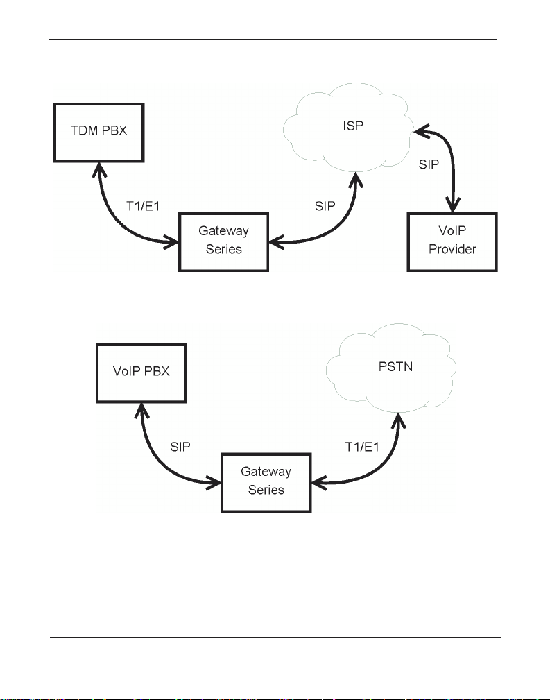
Digium's Gateway Series is a converged media gateway product line
designed to interface between TDM (T1/E1) and IP networks (SIP). The
Gateway Series connects lega cy telephone systems to IP networks and
seamlessly integr ates VoIP PBXs with the PSTN. Powered by innovative
hardware and software solut ions, Digium’ s Gat eway Series are managed
by a simple, intuitive web-based interface.
Digiu m, In c . Page 12
Page 13

Supported Voice Modes:
PRI CPE and PRI NET (T1 / E1)
– National ISDN 1 / NI1
– National ISDN 2 / NI2
– EuroISDN
– 4ESS (AT&T)
– 5ESS (Lucent)
– DMS100
– Q.SIG
E&M (T1 only)
– Wink
– Feature Group B
– Feature Group D
Chapter 1: Overview
FXO and FXS (T1 only)
– Ground Start
– Loop Start
– Loop Start with Disconn ect Detect
SIP
Example scenarios utilizing the Gateway Series are illustrated in Figure 1
and Figure 2 on page 14.
Digium, Inc. Page 13
Page 14
Chapter 1: Overview
Figure 1: TDM PBX to VoIP Scenario
Figure 2: VoI P PB X to T D M Scen ario
Digium, Inc. Page 14
Page 15

Chapter 1: Overview
Echo-Cancellation
Administrators connecting their Gateway Series appliances to the PSTN
or other devices are likely to be placing calls that will result, at some
point, in an unbalanced 4-wire/2-wire hybrid. The result of this hybrid is
the reflection of a near-end echo to the calling party. Elimination of this
echo is the responsibility of echo cancellation.
The Gateway Series appliance utilizes hardware-based voice processors
for echo cancellation an d codec tra nscoding. Its hardware echo canceller
is designed to handl e up to 128m s of e cho cancel lation ac ross a ll channe ls
and provides a G.168 compliant echo cancellation solution.
If not explicitly disable d in the Gateway Series web GUI, the hardwarebased echo canceller will automatically operate and cancel all network
echo within its tail range (1024 taps).
Digium, Inc. Page 15
Page 16

Chapter 2 Unit Installation
This chapter provides the following information:
Unpacking the Unit on page 17
Shipmen t Ins pec ti o n on page 18
Front Panel Identification on page 19
Unit Identi fica tio n on page 22
Hardware Installat ion on page 23
Note: The Gateway Series applia nce installation instructions are
written so that they will apply to any model in the seri es. Examples
and model specific information are included as needed.
Digiu m, In c . Page 16
Page 17

Chapter 2: Unit Installation
Unpacking the Unit
When you unpack your unit, carefully inspect it for any damage that m ay
have occurred in shipment. If damage is suspected, file a claim with the
carrier and contact the reseller from which the unit was purchased. If the
unit was purchased direct from Digium, c ontact Digium Te chnical
Support at +1.256.428.6161. Keep the original shipping container to use
for future shipment or proof of damage during shipment.
Note: Only qualified service personnel should install the unit. Users
should not attempt to perform thi s function themselves. The installer
must ensure that the equipment is reliably earth grounded in
accordance with the National Electrical Code.
Digium, Inc. Page 17
Page 18

Chapter 2: Unit Installation
Shipment Inspection
The following items are includ ed in shipment of a Gateway Series
appliance:
Gateway Series applianc e
Power cord with attached T1/E1 loopback plug
Mounting brackets (2 each)
Bracket mounting screws, #8-32 black truss head, Phillips, 3/16”
length (6 each)
Side-by-side mounti ng screws, #6-32 pan head, Phillips, 3/16” length
(3 each)
Side-by-side mounting shoulder washers (3 each)
Rubber feet (4 each)
Ground nut
Double-crimp ground ring term inal
Quickstart Guide
Note: After inspecting the shipment, Digium requires that the
appliance be registere d for support eligibi lit y. Unregister ed appliances
are not eligible for Digium suppo rt. Please refer to Free Installation
Support on page 57 for additional information on how to obtain
assistance from Digium Technic al Support.
Digium, Inc. Page 18
Page 19
Chapter 2: Unit Installation
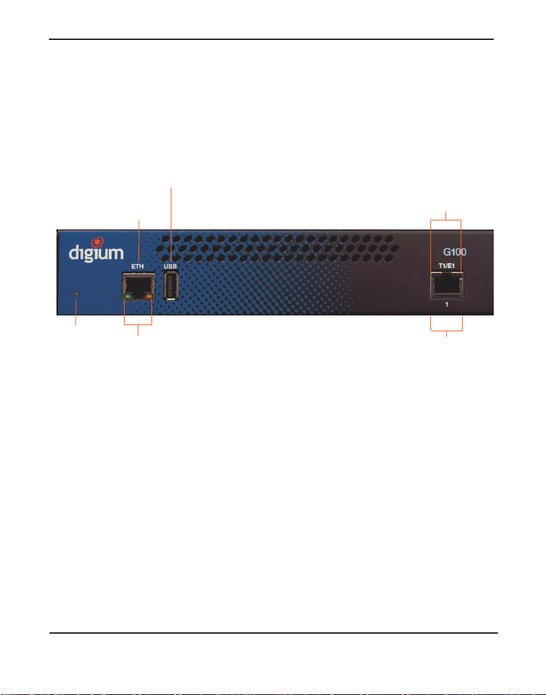
Gigabit
Ethernet
T1/E1
Port
Device
Status
USB
Recovery
Ethernet
Status
T1/E1
Status
Front Panel Identification
This section describes the components on the front panel of the Gateway
Series models.
Figure 3: G100 Single Port Appliance
Digium, Inc. Page 19
Page 20
Chapter 2: Unit Installation
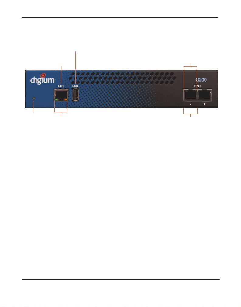
Gigabit
Ethernet
T1/E1
Port
Device
Status
USB
Recovery
Ethernet
Status
T1/E1
Status
Figure 4: G200 Dual Port Appliance
Device S tatus - This LED corresponds to the status of the Gateway
Series appliance. See Frequently Asked Questions on page 54 for
more information.
Gigabit Ethernet - This 10/100/1000BaseT Ethernet port provides
the ability to connect to an int erna l or external network using an RJ45
interface and support s Auto-MDIX. It is used to pass Ethernet packetized voice and web management data between the Gateway Series
and the network. See Gigabit Ethernet Port Pinouts on page 58 for
more information.
Ethe rn et St at us - The se LEDs correspond to the status of the Ethernet
connection. See Frequently Asked Questions on page 54 for more
information.
Digium, Inc. Page 20
Page 21

Chapter 2: Unit Installation
USB Recovery - This port can be used to perform a firmware recovery
and configuration reset. See Fi rmwar e Recovery and Configurat ion
Reset on page 52 for more information.
Warning! The USB Recovery port provides a limited amount of
current which is suf ficient only to power a USB flash drive. Do not
connect any other type of device to this port. The USB flash drive
should be fully USB 2.0 compliant.
T1/E1 Port( s) - These ports are used for connecting T1 or E1 cables.
See RJ45 T1/E1 Port Connector on page 59 for more informat io n.
T1/E1 Status - These LE D s corr esp o nd to the statu s of the T1/E1
ports. See Frequently Asked Questions on page 54 for more infor-
mation.
Digium, Inc. Page 21
Page 22

Chapter 2: Unit Installation
Unit Identification
The defining character istic of the Gateway Series models are the number
of ports supported. See Table 1 for a list of the various models.
Table 1: Gateway Series Models
Model Type Ports
G100 T1/E1 1
G200 T1/E1 2
Digium, Inc. Page 22
Page 23

Chapter 2: Unit Installation
Hardware Installat ion
This sectio n describes how to properly install the hardwa re for a Gateway
Series appliance.
Caution
Only qualified service personnel should continue with
hardware installation and confi guration of the Gateway Ser ies
appliance. Users should not attempt to perform these functions
themselves.
Caution
This equ ipmen t is intend ed for us e in Re stric te d Access A reas
only where equipotential bonding has been applied.
Grounding
The Gateway Series appliance must be properly earth gr ounded for safety
reasons. If the unit is not properly earth grounded, the unit and/or other
equipment connected to the unit could be damaged. If a Gateway Series
appliance is damaged while it is imprope rly grounded, the warranty on
the Gateway Series appliance is void.
A ground lug is located on the opposite side from the front panel of a
Gateway Series a pplian ce. Atta ch a n appropr iate l eng th and gauge of wire
to the double-crimp ground ring terminal. The wire length should be as
short as possible, and gauge should be 18 AWG or greater. Stranded or
solid wire is acceptable . Wire is not provided with the Gateway Series
appliance. Double crimp the ground ring terminal to the wire. Next, slide
the ground ring terminal over the ground lug. Then fasten the ground ring
Digium, Inc. Page 23
Page 24

Chapter 2: Unit Installation
terminal to the ground lug using the gro und nut. The ground nut must be
turned clockwis e to tigh ten it o nto th e groun d lug. The oppos ite end of the
wire that is connected to the ground ring terminal should be securily
fastened to an unpainted metalic section of a properly earth grounded
equipment rack. A connector for the opposite end of the wire is not
provided with the Gateway Series appliance.
Note: Taking i nto consi deration the r equir ements of a ll equipment that
is connected to or sharing the rack, the equipment rack should be
properly earth grounde d. Ref er to the manufacturer of the rack for
instructions on how to properly e arth ground the rack.
Important
Use only a grounded electrical outlet when connecting the
Gateway Series appliance to a power sour ce. If you do not
know whether the outlet is grounded, consult with a qualified
electrician.
Digium, Inc. Page 24
Page 25

Chapter 2: Unit Installation
Mounting
The included hardware allows the Gateway Series appliance to be wall
mounted, rack mounted side-by-side with another Gateway Series
appliance, or placed flat on a level surface. If a single Gateway Series
appliance is to be rack mounted, the optional long mounting bracket (not
supplied, part number 3244-00042) must be used. The optional long
mounting bracket can be ordered by contact ing a Digium reseller or
Digium directly.
Important
Reliable ear th grounding of ra ck-mount equipment should be
maintained. Particular atte ntion should be given to provide
connection other than direct connections to the branch circuit
(e.g., use of power strips).
Important
Mounting of the Gateway Series appliance in a rack should be
such that no hazardous condition is achieved due to uneven
mechanical loading. Do not place heavy objects on top of the
unit, or pull down on the mounted unit. Consider the
mechanical l oadi ng of ex terna l cable s. The wei ght of th e cable s
can pull on the unit and create unev en loading. Secure heavy
cables with external cable trays.
Important
If rack mounting, ins tall the Gateway Ser ies appliance in a rack
so that the amount of airflow r equired for safe operation is not
compromised.
Digium, Inc. Page 25
Page 26

Chapter 2: Unit Installation
Important
If the Gateway Series appliance is installed in a system that is
in turn installed in a closed or mu lti-unit rack a ssembly, the
operating ambient temperature of the rack environment may be
signific antly great er than the room ambient. While the
maximum safe operat ing temperature is 50°C, considerat ion
should be given to ins talling the unit in an environment
compatible with the maximum recommended ambient
temperature of 45°C for long ter m reliabili ty and maximum
performance.
Single Unit Rack Mount:
In order to rack mount the Gateway Series appliance by itself, place one
of the short mounting brackets on the front of one side of the Gateway
Series appliance. Line up the holes from the mounting bracket to the
threaded holes on the front sid e of the Gateway Ser ies appliance. Two #8
black truss head sc rews should be inserted and tur ned clockwise to fasten
the mounting bracket. Do not over-tighten. Repeat these steps when
installing the optional long mounting bracket (not supplied, part number
3244-00042) on the othe r side of the Gateway Series appl iance. Then use
another 2 #8 black truss head screws on each mounting bracket to secure
the Gateway Series ap pl ian ce to a rack .
Digium, Inc. Page 26
Page 27

Chapter 2: Unit Installation
Side-by-s ide Rack Mount:
In order to rack mount the Gateway Series appliance side-by-side with
another Gateway Series appliance, place one of the short mounting
brackets on the front of the le ft side of the first Gateway Serie s appliance.
Line up the holes from the mounting bracket to the threaded holes on the
front of the left side of the first Gateway Series appliance. Two #8 black
truss head screws should be inserted and turned clockwise to fasten the
mounting bracket. Repeat these steps when installing a short mounting
bracket on the front of the right sid e of the seco nd Gateway Series
appliance.
Each of the three #6 pan head screws should be inserted into a shoulder
washer as shown in Figur e 5 on page 28. Make sur e the narrow side of the
shoulder washer is away from the head of the screw. The three screws
should then be insert ed and turned clockwise to fasten to th e side-by-side
holes on the right side of the first Gateway Series appliance. Do not
overtighten the screws or the shoulder washers could be damaged.
Connect the first and second Gatewa y Series appliances together by
putting the heads of three screws & shoulder washers into the three keyed
insets. Then push down on th e second Gateway Ser ies applia nce a s sh own
in Figure 5. Make sure the units ar e flat against e ach other before pushing
the second unit down. Otherwise the shoulder washers may be damaged.
Use two truss head screws (not supplied) on each mounting bracket to
secure both Gateway Series appl iances to a rack.
Digium, Inc. Page 27
Page 28

Chapter 2: Unit Installation
Figure 5: Side-by-side Rack Mounting
Wall Mou nt:
In order to wall mount the Gateway Series appliance, the short mounting
brackets should be flipped an d rotate d, and fastened on the middle of the
right and left sides of the Gateway Series appliance as shown in Figure 6
on page 29. The unit should be mounted at or below eye level to pr operly
view the LEDs. In addition, the Gateway Series appliance should be
properly oriented as shown in Figure 6. Orientations other than those
shown in Figu re 6 are not acce p tab le.
Digium, Inc. Page 28
Page 29

Chapter 2: Unit Installation
Front side
Right side down
Back side down
Back side Left side
Right side
If the Gateway Series applian ce is placed in the “right side down”
orientation, the 2 remaining #8 black truss head mounting screws should
be fully inser ted into the screw hole s near the front of the right side of the
Gateway Series applianc e. In addition, the three #6 pan head screws
should be ful ly inserted into the side-by-side hole s on the right side of the
first Gateway Series appl iance.
Note: The Gateway Series appliance must be properly grounded for
safety reaso ns. I f the uni t i s not prope rly groun ded, d amage coul d a rise
to the unit and/or other equipment connected to the unit.
Figure 6: Acceptable Wall Mount Orientations
Digium, Inc. Page 29
Page 30

Chapter 2: Unit Installation
Level Surface:
In order to place the Gateway Series appliance flat on a level surface, the
rubber feet should be adhered to the 4 corners of the bottom of the
Gateway Series applianc e. This will help secure the Gateway Series
appliance to t he surfa ce i t is pla ced on.
Note: The Gateway Series appliance must be properly grounded for
safety reaso ns. I f the uni t i s not prope rly groun ded, d amage coul d a rise
to the unit and/or other equipment connected to the unit.
Digium, Inc. Page 30
Page 31

Chapter 2: Unit Installation
Connecting Ports
A description of each of the front panel connectors on a Gateway Series
appliance is available in the section titled Front Panel Identification on
page 19. Please refer to that section to determine what should be
connected to each connector.
Caution
This unit must be connected to the Teleco mmu nications
Network in your country using an approved line cord, e.g.: for
Australia use only line cords complying with ACA Technical
Standard TS008.
Caution
Connect only equipment approved for use in your specifi c
country to the telecommunications ne twork voltage circuit
ports.
Connections to a Gateway Series appl iance should be made in the
following order.
1. Gigabit Ethernet
2. T1/E1 Port(s)
3. Power Cord
Digium, Inc. Page 31
Page 32

Chapter 2: Unit Installation
Connecting to the Gateway Series
The Gateway Series web GUI may be accessed by either its DHCP or
statically assigned IP address. The following browsers are supported:
IE 9
Firefox 8 or newer
Chrome 15
Safari 5
Connecting via DHCP assigned IP address
1. If a DHCP se rver exists on th e network that the Gat eway Series appli-
ance will be placed on, connect one end of an Ethernet cable to the
Gateway Series applianc e's Ethernet port, and the other end to an
Ethernet connectio n on a network switch or hub. This step will connect your Gateway Series applia nce to your network so that the Gateway Series web GUI may be accessed from your network.
2. Using a Gateway Series supported web browser, open a browser
window from a computer on your network and enter the IP address
for the Gateway Series applia nce using HTTPS (e.g. https://[IP]). If
you do not connect using HTTPS, a browser error will be displayed.
The IP address for the Gateway Series web GUI will be assigned by
the DHCP server on the network. The DHCP server on the network
will need to be accessed to determine the IP address assigned to the
Gateway Series appliance. The default username for the Gateway
Series web GUI is admin, and the default password is admin.
Digium, Inc. Page 32
Page 33

Chapter 2: Unit Installation
3. It is highly r ecommended that the admin password be change d using
the System Admini s trators menu on the web GUI.
4. Next, the IP configuration options should be configured on the
Gateway Series appliance. See IP Configur ation on page 35.
Connecting via Statically assigned IP addre ss
1. If a DHCP server does not exist on the network that the Gateway
Series appliance will be placed on, c onne ct one end of an Ethernet
cable to the Gateway Series appliance's Ethernet port, and the other
end to an Ethernet connection on a computer. That computer wil l
need to use the network configuration listed below. This step will
connect your Gateway Series appl iance to your computer so that the
Gateway Series web GUI may be accessed from your computer.
Network settings for computer connecting to Gateway Series
IP: 192.168.69.2
Netmask: 255.255.255.0
Broadcast: 192.168.69.255
2. Using a Gateway Series supported web browser, open a browser
window and enter the IP address for the Gateway Series appliance
using HTTPS (e.g. https://[IP]). If you do not connect using HTTPS,
a browser error will be displayed. The default IP address for the
Gateway Series web GUI is 192.168.69.1. The defa ult username for
the Gateway Series web GUI is admin, and the default password is
Digium, Inc. Page 33
Page 34

Chapter 2: Unit Installation
admin.
3. It is highly r ecommended that the admin password be change d using
the System Admini s trators menu on the web GUI.
4. Next, the IP configuration options should be configured on the
Gateway Series appliance. See IP Configur ation on page 35.
Digium, Inc. Page 34
Page 35

Chapter 2: Unit Installation
IP Configuration
The general networking and configuration server options in the Gateway
Series web GUI should be configured before others.
Note: Saving changes to the IP configuration requires a restart ,
resulting in all active calls being dropped. We recommend against
making these changes during busi ness hours.
Figure 7: IP Configuration Menu
Digium, Inc. Page 35
Page 36

Chapter 2: Unit Installation
The General Netw orking Opti ons are described below.
Hostname - Specify the hostname of the Gateway Series applia nce.
Obtain an IP Address via DHCP - If a DHCP serv er exi s ts on the
same network as the Gateway Series appliance, this feature may be
enabled for the IP address to be dynamically assigned via DHCP.
Note: It is recommended that this feature be disabled if the DHCP
server is not configured to always prov ide the same IP address
based on MA C add res s. If thi s is the cas e, the Gat ew ay Series
appliance’s network settings should be manually configured. The
MAC address of the Gateway Series appliance is printed on a
sticker on the bottom of the unit.
System IP Address - If Obtain an IP Addr ess v ia DHCP is disa bled,
specify the sta tic IP addre s s for the Gate w ay Seri es app lian c e.
Network Mask - If Obtain an IP Address via DHCP is disabled,
specify the network mask for the Gateway Series appliance.
Gateway Address - If Obtain an IP Address via DHCP is disabled,
specify the gat eway address for the G atew a y Seri es ap plian ce . T he
gateway address is usually the address of the router on the network.
DNS Addresses - If Obtain an IP Address via DHCP is disabled,
specify up to 3 DNS servers to be used by the Gateway Series appliance. A DNS ser ve r may al so be referred to as a namese rv er.
Also Continue Using Default Install IP Address - Leaving this
option enabled will allow the Gateway Series appliance to listen for
network requests on its factory default IP address.
Note: For security purposes, it is recommended that this feature be
disabled after initial IP configuration is complete. After this feature is
disabled, the Gateway Series ap pliance will be accessible only from
Digium, Inc. Page 36
Page 37

Chapter 2: Unit Installation
the IP address that is assigned by the DHCP server or statically
configured.
– Factory Default IP Address - Displays the factory default IP
address assigned to the Gateway Series appliance.
– Default Install Mask - Displays the factory default network mask
of the Gateway Series applianc e.
The Gateway Se ries a pplianc e is capabl e of loadi ng i ts con figur ation from
a configuration serve r on reboot. This allows Gateway Series appliances
to be quickly and easily deployed at multiple locations with minimal
interaction fro m an administrator.
In order to generate a configuration to place on a configuration server,
configure a Gateway Series appliance, generate a backup from the web
GUI as described i n Backups on p age 49, a nd place t he backup file on the
configuration ser ver at the path described below.
Note: The format of the path to the configur ation server is protocol://
[user:password@]hostname_or_ip[/path]. The protocol may be either
tftp, ftp, or http. The Gateway Seri es ap pl ia nce w ill requ es t a
configuration data base with the filename of xxxxxxxxx xxx.tgz , where
xxxxxxxxxxxx is the unit’s MAC address, from the configur ation
server. The MAC address of the Gateway Series appliance is pri nted
on a sticker on t he bottom of the unit. FTP and HTTP normally do not
require a username and password.
Digium, Inc. Page 37
Page 38

Chapter 2: Unit Installation
The Configuration Server options are specified be low.
Reload Remote Config on Reb oot - Leaving this option enabled will
allow the Gateway Series a ppliance to request that its configu rati on be
reloaded from a configuration server on every reboot.
Note: If this feature will not be used, it is recommended that it be
disabled.
Get Config Server from Option 66 via DHCP - If Obtain an IP
Address via DHCP is enabled and the DHCP server specifies the path
and configuration database file on the configuration server using
Option 66, this feature may be enabled f or all Gateway Series configuration settings to be automatically configured using a configuration
server. The Reload Remote Config on Reboot option must be
enabled in order to activate this feature. Refer to the note on page 37
for proper syntax when specif ying the path and configur ation da tabase
file.
Configu ra tio n Ser v er - If Obtain an IP Address via DHCP is
enabled and Get Config Server from Option 66 via DHCP is dis-
abled, the path to the configura tion server may be statically defined
using this option . The Reload Remote Config on Rebo ot op tion must
be enabled in order to activate this feature. Refer to the note on
page 37 for proper synt ax when specifying the path and conf iguration
database file.
Digium, Inc. Page 38
Page 39

Chapter 3 Configuration
The Gateway Series appliances have a variety of configuration options.
This chapter provide s information on how to use the Gateway Series web
GUI to configure an appliance without the need of command-line tools,
and an overview of the available configuration sections.
Context-sensitive help buttons are provided above most sections of the
Gateway Series web GUI. Clicking on a help button will open a new
window which contains a detailed description of the options available for
that section. The help buttons appear as .
Digiu m, In c . Page 39
Page 40

Chapter 3: Configuration
The Gateway Series appliance should already be connected to your
network or computer , as described in Connecting to the Gateway Series
on page 32. Using a Gateway Series supported web browser, open a
browser window and enter the IP address for the Gateway Series
appliance using HTTPS (e.g. https://[IP]). If you do not connect using
HTTPS, a browser error will be displayed. The login screen will be
displayed. An administrator username and password must be entered to
proceed. The default username for the Gateway Series web GUI is
admin, and the default password is admin.
Figure 8: Login Screen
Digium, Inc. Page 40
Page 41

Chapter 3: Configuration
The Gateway Series web GUI is div ided into the following main sections.
Settings and Configuration on page 42
Logging and Reporting on page 46
St atus and Diagnostics on page 47
Maintenance on page 49
Figure 9: Main Menu
Digium, Inc. Page 41
Page 42

Chapter 3: Configuration
Settings and Configuration
This section provides the ability to configure SIP and TDM settings,
create call routing groups and rules, manage system administrators, and
set up networking. Included are the following sections.
SIP Endpoi n ts on page 42
Advanced SIP Settings on page 43
T1/E1 on page 43
Call Routing Groups on page 43
Call Routing Rules on page 44
SIP Endpoi n ts
This section provides the abi lity to add and modify SIP endpoints, and
configure call , media, and fax settings. A SIP endpoint will typically be a
SIP PBX or SIP provider connected to the Gateway Serie s appliance.
Included are the following sections.
Main - Primary options for SIP endpoint configuration
Call Setting s (Adv a nc ed) - DTMF, Caller ID, signaling, and
advanced timer settin gs
Media Setti ngs (A dva n ced) - Media types and priorities, codecs set-
tings
Fax Settings (Advanced) - Fax related se ttings
Digium, Inc. Page 42
Page 43

Chapter 3: Configuration
Advanced SIP Settings
This section provi des the abili ty t o add a nd modify a dvanced SI P sett ings.
These settings are for experienced administrators only. Please take care
when modifying any of these setting s. The defau lt values should be
sufficie nt for most applications. Included are the following sections.
Networking - General, NAT, RTP, RTCP, and DTMF settings
Parsing and Compatibility - General, SIP methods, Caller ID, timer
configuration, and outbound registrations
Security - SIP domains, authentication, and guest calling settings
Media - ISDN media, QOS/TOS settings
Fax - Fax related settings
T1/E1
This section provides the ability to configure the T1/E1 hardware in the
Gateway Series applianc e. Included are the following sections.
General - General options for T1/E1 configura tion
Port # - Port specif ic options for interface type and signaling
Call Routing Groups
This section provides the ability to add and modify SIP and T1/E1 call
routing groups. A call routing group allows a group of channels to be
addressed when creating a cal l routing rule.
Digium, Inc. Page 43
Page 44

Chapter 3: Configuration
Call Routing Rules
This section provides the ability to add and modify call routing rules. A
call routing rule deter mines how a call is handled based upon certain
characteristic s such as inbound channel and DID. It is also possible to
manipulate matched numbers befor e connecting outbound calls.
System Administrators
This section provides the ability to add and modify system administrators
for access to the Gateway Series web GUI.
IP Configuration
This section provides the ability to configure IP options for the Gateway
Series appliance. See IP Conf iguration on page 35 for more information.
HTTPS
This section provide s the ability to supply your own certificate for secure
connection to the Gateway Series web GUI. A self-signed certificate is
provided by default.
Digium, Inc. Page 44
Page 45

Chapter 3: Configuration
Access Control
This section provides the ability to limit access to the web GUI and SIP
traffic thr ough the Gateway Series appliance. All other protocols are
blocked.
Digium, Inc. Page 45
Page 46

Chapter 3: Configuration
Logging and Reporting
This section provides the ability to configure and view system statistics
and logging of the Gateway Series applia nce. Included are the following
sections.
Statistics - Displays statistics for active calls and calls processed, and
displays a summary of active call s in progre ss
System Log - Settings for system logging via Syslog
Digium, Inc. Page 46
Page 47

Chapter 3: Configuration
Status and Diagnostics
This section provides the ability to view connection status, system
information, perform advanced debugging, and troubleshoot problems
with diagnostic tools . In cluded are the following sections.
Connection Status on page 47
System Information on page 47
Advanced Debugging on page 48
Technical Su pp o rt on page 48
Connection Status
This section provide s the ability to view the connection status of network
interfaces, SIP endpoints, and T1/E1 interfaces. Included are the
following sections.
Network - Status of network interfaces
SIP Endpoi n ts - Status of SIP endpoints
T1/E1 Inte rfaces - Status of T1/E1 interfaces per port
System Information
This section provides the ability to view system information on the
Gateway Series appliance, including model number, software version,
MAC address, uptime, and system time.
Digium, Inc. Page 47
Page 48

Chapter 3: Configuration
Advanced Debugging
This section provides the ability to record and download debug logs for
troubleshooti ng. I ncluded are the following sections.
Debugging Sessions in Pr ogr ess - Displ ays exi sting logs or recor ding
sessions in progress
St art a New Debugging Session - TCP traffic, gateway logging, and
system logging settings for starting a new debugging session
Technical Su pp o rt
This section provides the ability to enable remote access for Digium
Support Personnel to acces s the Gateway Series appliance for support
purposes.
Digium, Inc. Page 48
Page 49

Chapter 3: Configuration
Maintenance
This section provides the ability to perform configuration backups,
register the unit, perform system updates, set the system clock, reboot,
and restore factory settings. Included are the following sections.
Backups on page 49
Software Updates on page 49
System Clock on page 49
System Reset on page 50
Backups
This section provides the ability to create and restore a backup. Included
are the following sections.
Download Backup - Download a backup in database format
Restore a Backup - Restore a backup in database format
Software Updates
This section provides the ability to perform a software update for the
Gateway Series applianc e.
System Clock
This section provides the ability to set the system clock on the Gateway
Series appliance.
Digium, Inc. Page 49
Page 50

Chapter 3: Configuration
System Reset
This section provides the ability to perform a system reboot, system
shutdown, or factory reset of the Gateway Series appliance.
Digium, Inc. Page 50
Page 51

Chapter 4 Troubleshooting
This chapter provides information regarding troubleshooting tools,
frequently asked questions, and possible resolutions as identified by
Digium Technical Support. Multiple resources are available to obtain
more information about Aster isk and Digium products. Please visit both
www .digium.com and www.asterisk.org f or more information.
Digiu m, In c . Page 51
Page 52

Chapter 4: Troubleshooting
Firmware Recovery and Configurat ion Reset
If a Gateway Series appliance is behaving unexpectedly or the password
is forgotten, a firmware recovery may need to be performed. The USB
Recovery port can be used to perform a firmware recovery using a
recovery image. The recovery image reformats the Gateway Series’ root
filesystem and reload s the appr opriate software on it. It will also
overwrite the configur ation database, returning the Gateway Series
appliance to its default configuration.
Note: It is highly recomme nde d to use an im age that is equal or
greater in version than the fi rmware that is currently installed on the
Gateway Series applianc e.
Every Gatew ay Series firmwar e rel eas e wi ll inclu d e a recov e ry ima ge.
The recovery image is located inside of a compressed zip file which can
be download ed fro m
http://downloads.digium.com/pub/telephony/gateway/recovery/. After
downloading the recovery image, the contents of the compressed zip file
must be extracted and copied to the root (i. e. parent) directory of an
empty USB flash drive.
Note: A USB flash drive is not provided with a Gateway Series
appliance. It must be purchased separately. The USB flash drive
should be at least 2GB in size and formatted with the FAT32
filesystem.
Next, power off the Gateway Series appliance. Then insert the USB flash
drive into the USB Recovery port. Power on the Gateway Seri es
appliance. The Gateway Series appliance will boot from the USB
Digium, Inc. Page 52
Page 53

Chapter 4: Troubleshooting
Recovery port and process the recovery image which was placed on the
USB flash drive.
Warning! Do not disconnect power during thi s process. The recovery
process will take at least 3 minutes to complete.
During this process, the Device Status LED will turn red for a fraction of
a second. Then it will turn amber for less than a minute. Next, it will run
red for about 2 minut es. Lastl y, the Devic e Sta tus LED wi ll remain of f. At
this point, it is safe to power off the Gateway Series appliance. Remove
the USB flash drive and power cycle the Gateway Series appliance.
Digium, Inc. Page 53
Page 54

Chapter 4: Troubleshooting
Frequently Asked Questions
What do the col ors of the D e vi ce Status LED indi ca te?
Red - Hardware is initializing.
Amber - Software is initializing. Hardware is initialized.
Green - Hardware and software are fully initialized and running.
What do the col ors of the Ethernet Status LED s indicate?
Steady Green (left side) - Active Link
Blin king Amber (right side) - Network activity
What do the col ors of the T1/E 1 Status LEDs indic ate?
Steady Green (right side) - Appl iance is in - s ync w i th the fa r e n d.
Steady Yellow (right side) - Appliance is synchronizing or is receiv-
ing a yellow alarm from the far end.
Steady Red (right side) - Appliance is not seeing far end, circuit is not
up, or cable is bad.
Singular Blinking Green (right side) - Line has been placed into
loopback mode.
Steady Blue (left side) - T1/E1 software driver is initialized, but con-
figuration is invalid.
All Off - T1/E1 software drive r is not initialized.
Digium, Inc. Page 54
Page 55

Chapter 4: Troubleshooting
What type of c able do I need for the T1/E1 ports on a Gateway Seri es
appliance?
A straight-through RJ45 T1/E1 cable is needed for connecting to the RJ45
ports on a Gateway Series applianc e when connec ting to the PSTN. If
connecting to a TDM PBX, a crossover RJ45 T1/E1 cable may be
required. The appropriate cables m ay be ordered from Digium by visiting
www.digium.com. Refer to Table A-2 on page 59 for pin assignments.
There is a slight echo. How can I adjust the sound quality?
First, verify that the Echo Cancellation option under the Port # menu of
T1/E1 Settings is enabled. If it is not, enable it. If echo persists, adjust the
RX Gain and TX Gain options on the same menu. For the gain options, it
is recommended to shift only between values of -5 and 5.
Digium, Inc. Page 55
Page 56

Chapter 4: Troubleshooting
Where can I find answers to additional questions?
Digium Technical Support (+1.256 .428.6161), or Toll Free in the U.S.
(+1.877.344.4861), is available 7am-8pm Central Time (GMT -6),
Monday - Friday. Please refer to Free Installat ion Sup po rt on page 57
for additional infor mation on how to obtain assistance from Digium
Technical Support.
Digium, Inc. Page 56
Page 57

Chapter 4: Troubleshooting
Free Installation Support
Digium hardware products include fre e installation support. In order to
receive this sup port, regis ter your Digiu m product u sing t he seri al number
located on the serialization sticker of your Digium unit.
Steps to receive installation support:
1. Record your product serial number.
2. Register your product at http://www.digium.com/register.
3. E-mail Digium Support via support@digium.com, or telephone via
+1.256.428.6000 or Toll-Free +1.877.DIGIUM.1.
Note: Digium does not provide support for unregistered products.
Digium, Inc. Page 57
Page 58

Appendix A
Pin 1
Pin 8
Pin Assignments
The RJ45 (8P8C) port labeled ETH on the Gateway Series
appliance is 8-pin. The pin assignments are identified in Table A-1.
Note: Category 5e or Category 6 cables are required for Gigabit
(1Gbps) operation up to 100 meters. Categor y 5 cables will work for
short runs, but the link speed may be limited over long distances.
Table A-1: Gigabit Ethe rnet Port Pinouts
Diagram Pin Description
1 Bi-directiona l pair A+
2 Bi-directional pair A3 Bi-directional pair B+
4 Bi-directional pair C+
5 Bi-directional pair C6 Bi-directional pair B-
Digiu m, In c . Page 58
7 Bi-directiona l pair D+
8 Bi-directional pair D-
Page 59

Appendix A: Pin Assignments
Pin 1
Pin 8
All RJ45 (8P8C) ports labeled T1/E1 on the Gateway Series
appliance are 8-pin. RJ45 jacks are also commonly referred to as
RJ48 when used for telecommunication. The pin assignments are
identified in Table A-2.
Table A-2: RJ45 T1/E1 Port Connector
Pin Description
1Rx Ring
2Rx Tip
3 Unused
4 Tx Ring
5Tx Tip
6 Unused
7 Unused
8 Unused
Digium, Inc. Page 59
Page 60

Appendix B Specifications
This appendix provides specifications, required environmental
conditions, and maximum power consumption for the Gateway
Series appliances.
Physical (All Units).
Size: 8.6” × 9.0” × 1.72” (21.84 x 22.86 x 4.37 cm)
Weight: 2 lbs 12 oz (1,247.38 gm)
Interfaces.
Local Loo p Access: E1, T1, PRI; RJ45 (A.K.A RJ48)
USB: Standard Type A Receptacle
Ethernet Access: 10/100 /1000base-T; RJ45
Power: Standard 3-p in IEC320-C13
Environment.
Temperature: 0 to 50° C (32 to 122° F) operation
-20 to 70° C (4 to 158° F) storage
Humidity: 0 to 90% non-condensing
Power Req uirem en ts .
Voltage: 100-240VAC, 50/60Hz
Current: 0.5A maximum, 67mA@120V or 33mA@240V typical
Power: 10W maximum, 7.5W typical
Digiu m, In c . Page 60
Page 61

Appendix C Gloss ary and Acronyms
8P8C 8 position 8 conductor
Module connector commonly used to terminate twisted pair.
ANSI American National Standards Institute
An organization which proposes and establishes standards for
international communications.
asynchronous
Not synchronized; not timed to an outside clock source. Transmission is
controlled by start bits a t the beginning and stop bits at the end of each
character. Asynchronous communica tions are often found in internet
access and remote office applications.
attenuation
The dissipation of a transmitted signal’s power as it travels over a wire.
bandwidth
The capacity to carry traffic. Higher bandwidth indicates the ability to
transfer more data in a given time period.
bit
The smallest element of information in a digital system. A bit can be
either a zero or a one.
Digiu m, In c . Page 61
Page 62

Appendix C: Glossary and Acronyms
bps bits per second
A measurement of transmission spe ed across a data connection.
BRI
Basic Rate ISDN
broadband
Broadband transmission sha res the bandwidth of a particular medium
(copper or fiber optic) to integrate multiple signals. The channels take up
different f requencies on the cable, integrating voic e, data, and video over
one line.
channel
A generic term for an individual dat a stre am. Ser vice providers can use
multiplexing techniques to transmit multiple channels over a common
medium.
Cat5
T wisted pair cable for carrying sign als for 10/100 Ethernet, telephony,
and video. Cat5 was superseded by Cat5e.
Cat5e
T wisted pair cable for carrying sign als for Gigabit Ethernet, telephony,
and video.
Digium, Inc. Page 62
Page 63

Appendix C: Glossary and Acronyms
CLEC Competitive Local Exchange Carrier
A term for telephone companies established after the
T elecommunications Act of 1996 deregulated the L ECs. CLECs compete
with ILECs to offer local service. See als o LEC and ILEC.
CO Central Office
The CO houses local switching equipment. All local access lines in a
particular geographic area terminate at this facility (which is usually
owned and operated by an ILEC).
CPE Cust ome r Premises Equip men t
T erminal equipment which is connected to the te lecommunications
network and which resides within the home or of fice of the customer . This
includes telephones, modems, terminals, routers, and television set-top
boxes.
DAHDI Digium Asterisk Hardware Device Interface
A telephony project dedicated to implementing a reasonable and
affordable computer telephony platform into the world marketplace. In
addition, the collective name for the Digium-provided dr ivers for Digium
telephony interface products.
DS0 Digital Signal, Level 0
A voice grade channel of 64 kbps. The worldwide standar d speed for
digitizing voice conversation using PCM (Pulse Code Modulation).
Digium, Inc. Page 63
Page 64

Appendix C: Glossary and Acronyms
DS1 Digital Signal, Level 1
1.544 Mbps in North America (T1) and Japan (J1) -up to 24 voice
channels (DS0s), 2.048 Mbps in Europe (E1) - up to 32 voice channels
(DS0s). DS1/T1/E1 lines are part of the PSTN.
DS3 Digital Signal, Level 3
T3 in North America and Japan, E3 in Europe. Up to 672 voice channels
(DS0s). DS3/T3/E3 lines are not part of the PSTN.
DTMF Dual Tone Multi-Frequency
Push-button or touch tone dial ing.
E1
The European equivalent of North Ameri can T1, transmits data at 2.048
Mbps, up to 32 channels (DS0s).
E3
The European equival ent of North American T3, transmits data at 34.368
Mbps, up to 512 channels (DS0s). Equivale nt to 16 E1 lines.
EMI E lectromagnetic Interference
Unwanted electrical noise.
full duplex
Data transmission in two directions simultaneously.
Digium, Inc. Page 64
Page 65

Appendix C: Glossary and Acronyms
FXO Foreign Exchange Office
Receives the ringing voltage from an FXS device. Outside lines are
connected to FXO ports.
FXS Foreign Exchange Station
Initiates and sends ringing voltage. Phones are connected to FXS ports.
G.711
A recommendation by the Telecommunicati on Standardization Sector
(ITU-T) for an algorithm designe d to transmit and receive mulaw PCM
voice and A-law at a digital bit rate of 64 kbps.
G.723.1
A recommendation by the Telecommunicati on Standardization Sector
(ITU-T) for an algorithm designe d to transmit and receive audio at 6.3
kbps or 5.3 kbps.
G.729a
A recommendation by the Telecommunicati on Standardization Sector
(ITU-T) for an algorithm designe d to transmit and receive audio at 8
kbps.
H.323
A recommendation by the Telecommunicati on Standardization Sector
(ITU-T) for multimedia communic ations over packet-based networks.
Digium, Inc. Page 65
Page 66

Appendix C: Glossary and Acronyms
HDLC High-Level Data Link Control
A bit-oriented synchr onous data link layer protocol developed by the
International Organization for Standardization (ISO).
IAX In te r - A steri sk eXchange
The native VoIP protocol used by Asterisk. It is an IETF standard used to
enable VoIP connections between Asterisk servers, and between servers
and clients that also use the IAX protoc ol.
iLBC internet Low Bitrate Codec
A free speech codec used for voice over IP. It is designed for narrow band
speech with a payload bitrate of 13.33 kbps (frame length = 30ms) and
15.2 kbps (frame length = 20ms).
ILEC Incu mbent Local Exch ange Carrier
The LECs that were the or iginal carr iers in the market pr ior to th e entry of
competition and theref ore have the dominant position in the market.
interface
A point of contact between two systems, networks, or devices.
ISO International Standards Organization
IVR Interactive Voice Menu
An interactive technology that allows a telephone system to detect voice
and keypad input.
Digium, Inc. Page 66
Page 67

Appendix C: Glossary and Acronyms
LED Light-emitting Diode
Linux
A robust, feature-packed open source operating system based on Unix
that remains freely available on the internet. It boasts dependability and
offers a wide range of compatibility with hardware and software. Asterisk
is supported exclusively on Linux.
loopback
A state in which the transmit signal is reversed back as the receive signal,
typically by a far end network element.
MGCP Media Gateway Control Protocol
multiplexing
Transmitting multiple signals over a single line or channel. FDM
(frequency divisi on multiplexing) and TDM (time division multiplexi ng)
are the two most common methods. FDM separates signals by dividing
the data onto different carrier frequencies, and TDM separates signals by
interleaving bit s one after the other .
mux multiplexer
A device which transmits multipl e signals over a single communications
line or channel. See multiplexing.
node
A terminal in a computer network.
Digium, Inc. Page 67
Page 68

Appendix C: Glossary and Acronyms
NT Network Termination
A device connecting the customer' s telephone or data equipment to the
local ISDN exchange carrier's line. NT devices are connected to TE
devices.
PBX Private Branch Exchang e
A smaller version of a phone company’s large centra l switching office.
Example: Asterisk.
PCI periph eral compo nent interconnect
A standard bus used in most computers to connect peripheral devices.
POP Point of Presence
The physical connection point between a network and a telephone
network. A POP is usually a network node serving as the equivalent of a
CO to a network service provider or an interexchange carrier.
POTS Plain Ol d Telephone Service
The public switched teleph one network (PSTN) is the network of the
world's public circuit-switched telephone networks. Originally a network
of fixed-line analog te lephone systems, the PSTN is now almost entirely
digital, and now includes mobile as well as fixed telephones.
PPP Point-to-Point Protocol
Type of communications link that connects a single device to another
single device, such as a remote terminal to a host computer.
Digium, Inc. Page 68
Page 69

Appendix C: Glossary and Acronyms
PRI
Prim a r y R ate IS D N
PSTN Public Switched Telephone Network
A communications network which uses telephones to establish
connections between two poin ts. Also referred to as the dial network.
PTMP Point-to-Multipoint
A connection where data is broadcast between more than two endpoints.
PTP Point-to-Point
A connection restricted to two endpoints.
PTT Post, Telegraph, and Tel ephone
The government agencies in many countries that traditionally operated
and monopolized the public postal, telegraph, and telephone service s.
QoS Quality of Serv ic e
A set of quality requirements fo r tele phone service.
RBOC Regional Bell Operating Companies
The creation of Regional Bell Operating Companies were a result of
AT&T's telephone monopoly being broken up in 1983.
REN Ringer Equivalence Number
An arbitrary v alue which d enotes the electr ical lo ad a tele phone r inger has
on a line.
Digium, Inc. Page 69
Page 70

Appendix C: Glossary and Acronyms
RJ11
A six-pin ja ck typically used for connecting telephones, modems, and fa x
machines in residentia l and business settings to PBX or the local
telephone CO.
RJ45
8P8C, un-keyed modular connector type for Ethernet over twisted pair.
Predominantly used in LAN and uses Unshielded Twisted Pair cable.
RJ48
8P8C modular connector type for T1 and ISDN termination over twisted
pair. While RJ45 and RJ48 use the same connector, they differ in their
wiring. RJ48 is commonly seen on T1 lines and uses Shielded Twisted
Pair cable.
SIP Session Initiation Protocol
An IETF standard for setting up sessions be tween one or more clients. It
is currently the leading signaling protocol for Voice over IP, gradually
replacing H.323.
T1
A dedicated digital carrier facility which transmits up to 24 voice
channels (DS0s) and transmit s data at 1.544 Mbps. Commonly used to
carry traff ic to and from private business networks and ISPs.
T3
A dedicated digital carrie r facility which consists of 28 T1 lines and
transmits data at 44.736 Mbps. Equivalent to 672 voice channels (DS0s).
Digium, Inc. Page 70
Page 71

Appendix C: Glossary and Acronyms
TDM Time Division Multiplexer
A device that supports simul taneous transmissi on of multiple data streams
into a single high-speed dat a stre am. TDM combines signals by
interleaving bit s one after the other .
TE Terminal Equipment
A device that is esta blished as a point of ter minati on of a communicat ions
circuit or channel. T erminal equipment comprises all customer premises
equipment (CPE). TE devices are connecte d to NT devices.
telco
A generic name which refers to the telephone companies throughout the
world, including RBOCs, LECs, and PTTs.
tip and ring
The standard terminati on on the two conduct ors of a telephone circuit;
named after the physical appear a nce of the contact areas on the jack plug.
twisted pair
T wo copper wires commonly used for telephony and data
communications. The wires are wrapped loosely around each other to
minimize radio frequency interference or interference from other pairs in
the same bundle.
USB Universa l S e ria l B u s
Industry standard defining communication protocols, cabl es, and
connectors used in a bus for connection, communication, and power
between elec tr oni c dev ices an d com p ute rs .
Digium, Inc. Page 71
Page 72

Appendix C: Glossary and Acronyms
V Volts
VoIP Voice over Internet Protocol
T echnology used for transmitti ng voice traffic over a data network using
the Internet Protoco l.
Digium, Inc. Page 72
 Loading...