

Page 1

2400 Series
AEX2400 / TDM2400P
User Manual
601-00013 Rev. C4
Page 2

445 Jan Davis Drive
Digium, Inc.
Huntsvil le, AL 35806
United States
Main Number: 1.256. 428.6000
Tech Support: 1.256.428.6161
U.S. Toll Free : 1.877.344.4861
Sales: 1.256.428.6262
www.digium.com
www.asterisk.org
www.asterisknow.org
© Digium, Inc. 2 013
All rights reserved.
No part of this publication may be copied, distributed, transmitted, transcribed, stored in a
retri eval s yst em , o r tran sl at ed int o a ny hu man or co mpu ter l angu ag e wit h ou t the p rio r wr i tte n
permission of Digium, Inc.
Digium, Inc. has made every effort to ensure that the instructions contained in this document
are ade q uate an d err o r free. T he m a nu f a ctu r e r w i ll, if n ec es s ary , explain issu es w h ic h may
not be covered by this documentation. The manufacturer’s liability for any errors in the
docume nts is limited to the correct ion of errors and the aforementioned advisory services.
This doc ument h as been p repar ed for us e by profe ssiona l and pr operly tr ained p ersonn el,
and the cus to m er as su m es fu ll re sp onsibi li ty w he n us in g it.
Adobe and Acrobat are registered trademarks, and Acrobat Reader is a trademark of Adobe
Systems Incorporated.
Asterisk, Digium, Switchvox, and AsteriskNOW are registered trademarks and Asterisk
Business Edition, AsteriskGUI, and Asterisk Appliance are trademarks of Digium, Inc.
Any oth er tr a dem ark s m en ti oned i n t he do cu me nt ar e t he pr op ert y of t h ei r r es pe ctiv e ow ner s.
Digium, Inc. Page 2
Page 3

Compliance Information
Compliance information for this product is available at
http://www.digium.com/ccs-compliance.
Digium, Inc. Page 3
Page 4

Introduction to 2400 Series Documentation
This manual contains product inf ormation for the 2400 Series card. Be
sure to refer to any supplementa ry documents or release notes that were
shipped with your equipment. The manual is organized in the following
manner:
Chapter/
Appendix
1
2
3
4
5
A
B
C
Title Description
Overview Identifies the card and type o f mo dules you received
with your 2400 Series card. Th is chapter covers
applicat ions and uses of the 2400 Series card in the
real world.
Card Installation Provides instructions for installing the card in your
PC, acquiring correct drivers , and checking device
compatibility.
Configuration Provides examples for configuring dial plan options.
FXS and FXO
Explained
Troublesh ooting Explains resolutions to common problems and
Pin Assignments L ists the conne c tors and pin assi gnments.
Specifications Details card specifications.
Glossary and
Acronyms
Describes the FXO (Foreign Exchange Office) and
FXS (Foreign Ex change Station ) mo dules and their
significance.
frequentl y as ked questions pertaining to card
installation and usage.
A list of te r m s and acronyms used throughou t t his
manual.
Digium, Inc. Page 4
Page 5
Symbol Definitions
Caution stat emen ts in dicate a c onditio n whe r e d amage to t he un it o r
its configuration could occur if operational procedures are not
followed. To reduce the risk of damage or injury, follow all steps or
procedures as instructed.
The ESD sym b o l in d i ca t es electrostat i c s ens i ti ve d e vi ces. Observe
prec autions for handling de vices. Wear a properly gr ounded
electrostatic discharge (ESD) wrist strap while handling the device.
The Electrical Hazard Symbol indicates a possibi lity of electrica l
shock when operat ing this unit in certain s ituations. To reduce the
risk of damage or injury, follow all steps or pr ocedures as
instructed.
Digium, Inc. Page 5
Page 6
User Cautions
Warning
This card must be used with the PC lid screwed down.
Telecommunications network voltages exist inside the PC!
The PC must be shut down and telec ommunications line connection
shall be removed before opening the PC.
Electrical Shock.
To re duce th e risk of inj ury , damage to the uni t or yo ur equi pment, do
not attempt to touch the modules while they are powered. The case
should be securely clo se d before power is applied to the unit.
Alarm Dialing Equipment.
If your home has special ly wired alarm equipment connected to the
telephone line, ensure the installation of the 2400 Series does not
disable your alarm equipment. If you have ques tions, consult your
telephone company or a qualified installer.
Servicing.
Do not attempt to service this card unless specifically instructed to do
so. Do not attempt to remove the card from your equipment while
power is present. Refer servicing to qualified service pe rsonnel.
Important Safety Instructions
Water and Moisture.
Do not spill liquids on this unit. Do not operate this equipment in a
wet environment.
Heat.
Do not operate or store this product near heat sources such as
radiators, air ducts, areas subject to direc t, intense sunlight, or other
products that pr oduce heat.
Caution.
To reduce the risk of fire, use only No. 26 AWG or larger
telecommunication wiring for networ k connections.
Digium, Inc. Page 6
Page 7
User Cautions
Caution.
This car d is not intended for home us e. It must be used in res tr icted
access locations and installed in UL Listed I.T.E. only.
Static Electricity.
To reduce the risk of damaging the unit or your equipment, do not
attempt to open the e nclosur e or ga in access to areas w here you are
not instructed to do so. Refer servicing to qualified service personnel.
Save these instructions for future reference.
Service Pe rsonnel Cauti on s
Warning.
This card must be used with the PC lid screwed down.
Telecommunications network voltages exist inside the PC!
The PC must be shut down and telec ommunications line connection
shall be removed before opening the PC.
Electrical Shock.
To re duce th e risk of inj ury , damage to the uni t or yo ur equi pment, do
not attempt to touch the modules while they are powered. The case
should be securely clo se d before power is applied to the unit.
Servicing.
Disconnect telecommunications network cable before opening the
cover or remo v in g t h e ca rd from the m o th erboard.
Labeling.
For safety reasons, only co nnect equipment with a
Telecommuni cations Compliance label. This includes customer
equipment previously labelled Permitted or Certified.
Caution.
Only connect r egula tory equipment (ap prov ed for use in your spe cific
country) to th e telecommunicatio ns ne twork voltage circuit ports.
Digium, Inc. Page 7
Page 8

Service Pe rsonnel Cauti on s
Caution.
This car d is not intended for home us e. It must be used in res tr icted
access locations and installed in UL Listed I.T.E. only.
Digium, Inc. Page 8
Page 9

TABLE OF CONTENTS
Table Of Contents
Chapter 1
Overview . . . . . . . . . . . . . . . . . . . . . . . . . . . . . . . . . . . . . . . . . . . . . . .13
Chapter 2
Card Installation . . . . . . . . . . . . . . . . . . . . . . . . . . . . . . . . . . . . . . . . .20
Echo-Cancellation . . . . . . . . . . . . . . . . . . . . . . . . . . . . . . . . . . . . . .17
What is Asterisk®? . . . . . . . . . . . . . . . . . . . . . . . . . . . . . . . . . . . . .18
Asterisk as a Switch (PBX) . . . . . . . . . . . . . . . . . . . . . . . . . . . . . . .18
Asterisk asa Gateway . . . . . . . . . . . . . . . . . . . . . . . . . . . . . . . . . .18
Asterisk in the Call Ce nter . . . . . . . . . . . . . . . . . . . . . . . . . . . . . . .19
Asterisk in the Network . . . . . . . . . . . . . . . . . . . . . . . . . . . . . . . . . .19
Asterisk Everywhere . . . . . . . . . . . . . . . . . . . . . . . . . . . . . . . . . . . .19
Unpacking the Card. . . . . . . . . . . . . . . . . . . . . . . . . . . . . . . . . . . . .21
Shipment Inspection . . . . . . . . . . . . . . . . . . . . . . . . . . . . . . . . . . . .21
Module Identification . . . . . . . . . . . . . . . . . . . . . . . . . . . . . . . . . . . .22
Card Identification . . . . . . . . . . . . . . . . . . . . . . . . . . . . . . . . . . . . . .25
FXS and FXO Connection . . . . . . . . . . . . . . . . . . . . . . . . . . . . . . .27
Hardware Installation . . . . . . . . . . . . . . . . . . . . . . . . . . . . . . . . . . . 29
Software Installation . . . . . . . . . . . . . . . . . . . . . . . . . . . . . . . . . . . .32
Installing Asterisk . . . . . . . . . . . . . . . . . . . . . . . . . . . . . . . . . . . . . .36
Chapter 3
Configuration . . . . . . . . . . . . . . . . . . . . . . . . . . . . . . . . . . . . . . . . . . . .38
Digium, Inc. Page 9
Driver Configuration . . . . . . . . . . . . . . . . . . . . . . . . . . . . . . . . . . . .39
Page 10

Table Of Contents
ConfiguringCard Features . . . . . . . . . . . . . . . . . . . . . . . . . . . . . . .44
Voicemail . . . . . . . . . . . . . . . . . . . . . . . . . . . . . . . . . . . . . . . . . . . .46
Testing Your Configuration . . . . . . . . . . . . . . . . . . . . . . . . . . . . . . .48
Chapter 4
FXS and FXO Explained . . . . . . . . . . . . . . . . . . . . . . . . . . . . . . . . . . .50
Identification. . . . . . . . . . . . . . . . . . . . . . . . . . . . . . . . . . . . . . . . . . .50
FXS Module . . . . . . . . . . . . . . . . . . . . . . . . . . . . . . . . . . . . . . . . . . 50
FXO Module. . . . . . . . . . . . . . . . . . . . . . . . . . . . . . . . . . . . . . . . . . .50
Using Your 2400 Series Card . . . . . . . . . . . . . . . . . . . . . . . . . . . . .51
Chapter 5
Troubleshooting . . . . . . . . . . . . . . . . . . . . . . . . . . . . . . . . . . . . . . . . .52
Appendix A
Pin Assignments . . . . . . . . . . . . . . . . . . . . . . . . . . . . . . . . . . . . . . . . .5 7
Appendix B
Specifications . . . . . . . . . . . . . . . . . . . . . . . . . . . . . . . . . . . . . . . . . . .5 8
Physical . . . . . . . . . . . . . . . . . . . . . . . . . . . . . . . . . . . . . . . . . . . . . . . . .58
Interfaces . . . . . . . . . . . . . . . . . . . . . . . . . . . . . . . . . . . . . . . . . . . . . . . .58
Environment. . . . . . . . . . . . . . . . . . . . . . . . . . . . . . . . . . . . . . . . . . . . . .59
Hardware and Software Requirements . . . . . . . . . . . . . . . . . . . . . . . . .59
Appendix C
Glossary and Ac ronyms . . . . . . . . . . . . . . . . . . . . . . . . . . . . . . . . . . . 6 1
Page 10 Digium, Inc. Release 2.0
Page 11

List of Figures
Figure : Sample Application - Channel Bank . . . . . . . . . . . . .14
Figure : Sample Application - Legacy PBX . . . . . . . . . . . . . .15
Figure : Sample Application - Toll-bypass . . . . . . . . . . . . . . .15
Figure : Sample Application - Analog to VoIP Transcoding . .16
Figure : TDM2400P Card (Model TDM2433E) . . . . . . . . . . .23
Figure : AEX2400 Card (Model TDM2433E) . . . . . . . . . . . . .24
Figure : Motherboard Slots . . . . . . . . . . . . . . . . . . . . . . . . . .28
Figure : Insert the Card . . . . . . . . . . . . . . . . . . . . . . . . . . . . . 29
Figure : Connect Power for FXS Quad Modules . . . . . . . . . .30
Figure : Example dmesg Screen Shot . . . . . . . . . . . . . . . . . .43
Figure : Sample Application . . . . . . . . . . . . . . . . . . . . . . . . . .49
1
2
3
4
5
6
7
8
9
10
11
Digium, Inc. Page 11
Page 12

List of T able s
Table 1: Example TDM2400P Card Configurat ions . . . . . . . . 25
Table 2: Example AEX2400 Card Configurations . . . . . . . . . 26
Table 3: Card Identifiers . . . . . . . . . . . . . . . . . . . . . . . . . . . . 34
Table B-1: Maximum Power Consumption . . . . . . . . . . . . . . . . . 60
Digium, Inc. Page 12
Page 13

Chapter 1 Overview
Chapter 1: Overview
The 2400 Series cards are versatile devices used for connecting your
phone network to the PSTN (Publi c Swit ched Tele phone Networ k) world.
This is accompli shed through phone lin es connected to the FXO (Foreign
Exchange Office) po rts and phones connected via the FXS (Foreign
Exchange Station) ports. The cards allow Asterisk to connect to your
phone network, creating an office type telephony environment.
There are a variety o f applications where the 2400 Series cards can prove
useful. Some examples are provided in the following figures.
Digium, Inc. Page 13
Page 14
Chapter 1: Overview
Figure 1: Sample Application - Channel Bank
Note: An FXS module should be connected only to a device that is
located inside of the same building to mi nimize lightning exposure.
Digium, Inc. Page 14
Page 15
Chapter 1: Overview
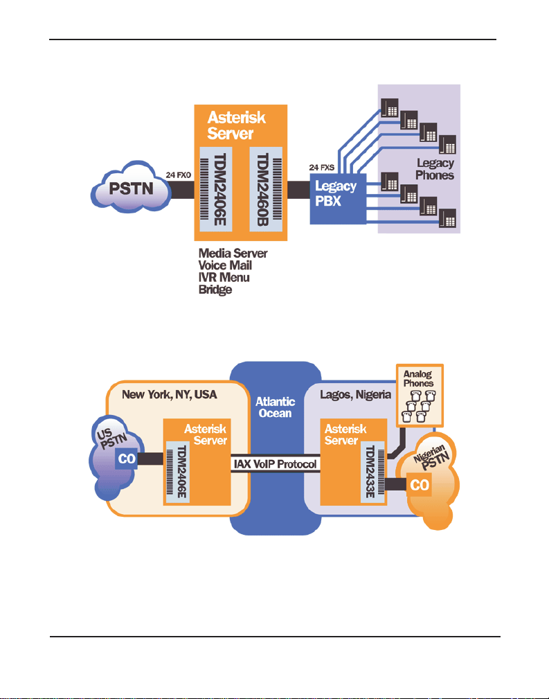
Figure 2: Sample Application - Legacy PBX
Figure 3: Sample Application - Toll-bypass
Digium, Inc. Page 15
Page 16
Chapter 1: Overview
Figure 4: Sample Application - Analog to VoIP Transcoding
Digium, Inc. Page 16
Page 17

Echo-Cancellation
Chapter 1: Overview
Users connecting the ir 2400 Serie s cards to t he PSTN or other devices ar e
likely to be placing calls that will result, at some point, in an unbalanced
4-wire/2-wire hybrid. The result of this hybrid is the reflection of a nearend echo to the calling party. Elimination of this ech o is the responsibility
of echo cancellation.
The 2400 Series cards, unless other wise equipped, utilize Asterisk to
perform software-based echo cancellation. Asterisk mainta ins a number
of open source echo c ancelers. These open sou rce echo cancelers provide
a moderate level of echo cancellation, but are not capabl e of dealing with
higher levels of, or more advanced, echoes.
Digium recommends that those users concerned about echo cancellation
purchase the VPMOCT032 hardware echo cancellation module. The
VPMOCT032 may be combined with both the TDM2400P and
AEX2400.
The VPMOCT032 is designed t o handle up to 128ms of echo ca ncell ation
across all channels and provides a G.168 echo cancellation solution.
Digium, Inc. Page 17
Page 18

Chapter 1: Overview
What is Asterisk®?
Asterisk is th e world’ s leading open source telephony engine and tool kit.
Offering fle xibility unheard of in the world of proprietary
communications, Asterisk empowers developers and integrators to create
advanced communication solutions...for free. Asterisk is released as open
source under the GNU General Public License (GPL), a nd it is available
for download free of charge. Asterisk is the most popular open source
software avai lable, with the Asterisk Community being the top influencer
in VoIP.
Asterisk as a Switch (PBX)
Asterisk can be configured as th e core of an IP or hybrid PBX, switching
calls, managing routes, enabling features, and connecting callers with the
outside world over IP, analog (POTS), and digital (T1/E1) connections.
Asterisk runs on a wide variety of opera ting systems including Linux,
Mac OS X, OpenBSD, FreeBSD, and Sun Solaris. It provides all of the
features you would exp ect from a PBX inclu ding many advanced f eatu res
that are often associate d with high end (and high cost) proprietary PBXs.
Asterisk's archi tecture is designed for maximum flexibility and supports
Voice over IP in many protocols, and can interoperate with almost all
standards-base d telephony equipment using relatively inexpensive
hardware.
Asterisk as a Gateway
It can also be built out as the heart of a media gateway, bridging the
legacy PSTN to the expanding world of IP telephony. Asterisk’s modular
architecture a llows it to co nvert betwee n a wide ran ge of communicat ions
protocols and media codecs.
Digium, Inc. Page 18
Page 19

Chapter 1: Overview
Asterisk as a Feature/Media Server
Need an IVR? Asterisk’s got you covered. How about a conference
bridge? Yep. It’s in there. What about an autom ated attendant? Asterisk
does that too. How about a replacement for your agi ng legacy voicemail
system? Can do. Unified messaging? No problem. Need a telephony
interface for your web site? Ok.
Asterisk in the Call Center
Asterisk has been adopted by call centers around the world based on its
flexibility. Call center and contact center developers have built complete
ACD systems based on Asterisk. Asterisk has also added new life to
existing call center solutions by adding remote IP agent capabilities,
advanced skills-based routing, predictive and bulk dialing, and more.
Asterisk in the Network
Internet Telephony Service Providers (ITSPs), competitive local
exchange c arriers (CLECS ) and even fi rst- tier in cu m be nts h av e
discovered the power of open source communications with Asterisk.
Feature servers, hosted services clusters, voicemail systems, pre-paid
calling solution s, a ll based on Asterisk have helped reduce costs and
enabled flexibility.
Asterisk Everywhere
Asterisk has become the basis for thousands of communications
solutions. If you need to communicate, Asterisk is your answe r. For more
information on Asteris k, visit http://www.asteris k.org or http://
www.digium.com.
Digium, Inc. Page 19
Page 20

Chapte r 2 : C ar d I n st a lla t io n
Chapter 2 Card Installation
This chapter provides the following information:
Unpacking the Card on page 21
Sh i pm en t Ins pec ti o n on page 21
Module Ide ntification on page 22
Card Identification on page 25
FXS and FXO Connection on page 27
Slot Compatibility on page 27
Hardware Installation on page 29
Software Installation on page 32
Installing Asterisk on page 35
Digium, Inc. Page 20
Page 21

Unpacking the Card
Chapte r 2 : C ar d I n st a lla t io n
When you unpack your card, carefull y inspect it fo r any damage that may
have occurred in shipment. If damage is sus pected, file a claim with the
carrier and contact the reseller from which the card was purchased, or
contact Digium Technical Support (+1.256.428.6161). Keep the original
shipping container to use fo r future shipment or proof of damage during
shipment.
Note: Only qualified service personnel should install the card. Users
should not attempt to perform thi s function themselves. The installer
must ensure that the equipment is permanently connected equipment,
pluggable type B or connecte d t o a socke t-outle t tha t has bee n checke d
to ensure that it is reliably earthed in accordance with the National
Electrica l Code.
This c a rd is in t en d e d fo r insta ll a ti o n in a R e s t r ic ted Acce ss
Location (RAL) only.
Shipment Inspection
The following items are includ ed in shipment of a 2400 Series card:
2400 Series card (TDM2400P or AEX2400)
FXO and/or FXS quad module(s) (depending on configuration)
Digium, Inc. Page 21
Page 22

Module Identification
Chapte r 2 : C ar d I n st a lla t io n
The 2400 Series c ard ships with FXO and/or FXS quad modules in plac e.
These are ide ntified by their color. Take a moment to ide ntify which quad
modules were shipped with your card.
FXO (Foreign Exchange Office) quad modules are Red
FXS (Foreign Exchange Station) quad modules are Green
See Figure 5 on page 23 for an example of the card shown with three of
each quad module.
Note: It is important to identify the type and location of your 2400
Series quad modules. You will need this information during the
Asterisk configuration.
There are multiple config urations in which the 2400 Series card may be
purchased. Each configuration consists of one to six FXS and/or FXO
quad modules. See Table 1 on page 25 for a complete list of possible
configurations.
The 2400 Series cards may also be combined with Digium’s hardwarebased echo cancel er , model VPMOCT032. Se e Figure 6 on page 24 f or an
example of the AEX2400 card shown with one of each quad analog
module and the echo cancellation module.
Digium, Inc. Page 22
Page 23

Chapte r 2 : C ar d I n st a lla t io n
FXS
FXO
Female
Quad Modules
Quad Modules
RJ-21X
(Green)
(Red)
36 5 4 2 1
Power
Supply
Connection
Echo
Cancellation
Module
Figure 5: TDM2400P Card (Model TDM2433E)
Digium, Inc. Page 23
Page 24

Chapte r 2 : C ar d I n st a lla t io n
FXS
FXO
Female
Quad Modules
Quad Modules
36 5 4 2 1
RJ-21X
Power
Supply
Connection
Echo
Cancellation
Module
Figure 6: AEX2400 Card (Model TDM2433E)
Digium, Inc. Page 24
Page 25

Card Identification
Chapte r 2 : C ar d I n st a lla t io n
There are multiple config urations in which a 2400 Series card may be
purchased. Each config urati on consist s of a comb ination o f quad module s
and may also include the VPMOCT032 echo cancellation module. See
Table 1 on page 25 for a list of the most common TDM2400P
configurations. See Table 2 on page 26 for a list of the most common
AEX2400 configurations . The li sts are not complete, but rather an
example of the configurati ons available.
It is easie st to identify your card by understanding the naming scheme f or
each card. The first two digits are the maxi mum port count of the card.
The third digit is the number of FXS (station) modules present on the
card. The fourth digit is the number of FXO (office) modules present on
the card.
Table 1: Example TDM2400P Card Configurations
Card ID
TDM2401B 1 quad FXO module
TDM2406B 6 quad FXO modules
TDM2433B 3 quad FXO modules and 3 quad FXS modules
FXO/FXS
Ports
TDM2451B 5 quad FXS and 1 quad FXO modules
TDM2460B 6 FXS modules
Digium, Inc. Page 25
Page 26

Chapte r 2 : C ar d I n st a lla t io n
Table 2: Example AEX2400 Card Configurations
Card ID
FXO/FXS
Ports
AEX2401B 1 quad FXO module
AEX2406B 6 quad FXO modules
AEX2433B 3 quad FXO modules and 3 quad FXS modules
AEX2451B 5 quad FXS and 1 quad FXO modules
AEX2460B 6 FXS modules
Digium, Inc. Page 26
Page 27

Chapte r 2 : C ar d I n st a lla t io n
FXS and FXO Connection
The 2400 Series card provides a 50-pin RJ-21X connector for access to
the FXS and/or F XO quad module s install ed in the six a vailable slots. The
diagram in Figure A-1 on page 57 provides the pinout fo r this connector.
Caution.
Only qualified service personnel s hould continue wi th
hardware inst allation and configuration of the 2400 Series
card. Use rs should not attempt to perform these functions
themselves.
Slot Compatibility
Check the type of card you received to be sure it is compatible with your
PCI slot. To determin e which slot you have, identif y it by comparing it to
those shown in Figure 7 on page 28.
Slot Number:
0: AGP Pro Slot
1: 64-bit 5.0 volt PCI Slot
2: 64-bit 3.3 volt PCI Slot
3: 32-bit 5.0 volt PCI Slot
4: PCI Express Slot
Digium, Inc. Page 27
Page 28
Chapte r 2 : C ar d I n st a lla t io n
Slots
0
1
2
3
4
Figure 7: Motherboard Slots
The TDM2400P card is a 32-bi t 33MHz card keyed for universal 3.3 volt
or 5.0 volt operation and works in any PCI 2.2 (or grea ter) compliant sl ot.
This means that in the motherboard shown in Figur e 7, th e TDM2400
card will fit into Slots 1, 2, or 3 (PCI slots) , but will not fit in to Slo t 0
(AGP slot) or Slot 4 (PCI Express slot).
The AEX2400 card is a PCI Express card. Slot 4, illustrated above, is a 1
lane (X1) PCI Express compliant slot . The AEX240 0 will work in any
PCI Express complia nt slot, including la ne lengths X4, X8, and X16. Th is
means that in the motherboard shown in Figur e 7, the AEX2400 will only
fit into Slot 4. The AEX2400 can not be u s e d in Slots 0 through 3.
Digium, Inc. Page 28
Page 29

Chapte r 2 : C ar d I n st a lla t io n
Hardware Installat ion
1. Now that you are acquainted with your card, power down your com-
puter and unplug it from its power source.
2. Attach a static stra p to your wrist and open the case.
3. Remove the bracket place holder and insert the card into a PCI
(TDM2400P) or PCI Express (AEX2400) slot. See Figure 8.
Figure 8: Insert the Card
4. If your card has an y FXS quad m odules, you will a ls o need to c onnect
the power cable from your computer’s power supply to the bottom of
the card. Insert a four-pin 12 volt connector (disk drive power supply
cable, e.g. hard drive) into the white plastic connector on the bottom
of the card. See Figure 9.
Digium, Inc. Page 29
Page 30

Chapte r 2 : C ar d I n st a lla t io n
Figure 9: Connect Power for FXS Quad Modules
Many modern PCs and servers do not have either spa re or any 12V power
connectors. If you have FXS modules on your 2400 Series card a nd your
computer does not have power cables available, then power must be
provided to the 2400 Series card by an alternate means. Digium provides
a solution to this problem with the optional PWR2400B (available
separately). This card is essentially a PCI bracket assembly that takes
power from an external DC power supply and routes it to two 15" power
cables inside the co mputer. You must have an available bracket slot to us e
the PWR2400B (either PCI, PCI Express or AGP).
A strap on the PWR2400B card allows the two power cables to take
power from the same DC s upply. The PWR2400B comes with one power
supply capable of supporti ng up to 24 FXS ports each, dr iving heavy
loads of up to 5REN. If more than 24 FXS ports with heavy loads are
connected to t he PWR2400B, the n a sec ond Di gium power Suppl y shoul d
be purchased. The shorti ng strap on t he PWR2400B should be removed i f
a second power supply is used.
Digium, Inc. Page 30
Page 31

Chapte r 2 : C ar d I n st a lla t io n
The PWR2400B does not connect to any bus inside the computer. It may
be used where ver there is an available PC I-s i ze bracket such as a PCI,
PCI Express, or AGP slot.
Note: The PWR2400B is not intended to supply power to any other
device, it is intended only to be used with UL Listed Digium analog
cards.
5. Replace the cover to your computer.
6. Plug all outside phone lines to the FXO ports (corresponding to the
red modules) and connect all phones to the FXS ports (green
modules) as needed using a patch panel or punch block. Se e Figure
A-1 on page 57 for the RJ-21X p in ass i gnments.
Electrical Shock.
To reduce the risk of injur y, damage to the unit or your
equipment, do not attempt to apply power to the unit while the
case is open. Pe rsonal injury or damage to the unit could occur
if the modules are touched while powered is applied.
Caution.
This unit must be connected to the Telecommunications
Network in your country using an approved line cord, e.g.: for
Australia us e only lin e cor ds c omplyin g with AS/CA S 008:2 010.
Caution.
Only connect regulatory equipment (approved for use in your
specific country) to the telecommunications network voltage
circuit ports.
Digium, Inc. Page 31
Page 32

Softw a r e In s t al la t io n
Chapte r 2 : C ar d I n st a lla t io n
Digium hardware requires drivers and libraries that are not integrated
with the Linux kernel. Digium hardware is only supported under Linux.
Digium recommends CentOS, Debian, R ed Hat, and Ubuntu di stribut ions
of Linux. However, m any other distributions are supp ort ed by Digium
Technical Support.
Digium’s software, including drivers and application software, may be
obtained from Digium’s download server at:
http://downloads.digium.com
For an introduction to Asterisk, Digium’s telephony software, including
additional infor mation on its configuration, setup, and features, please
refer to:
http://www.asterisk.org
For the latest information on se tting up and configuring DAHDI drivers
for your Digium hardwar e product, please refer to t he lat est relea se of t his
manual which is available fro m the product-specific documentation
section at:
http://www.digium.com
To install your 2400 Series card, you will need:
Linux 2.6 kernel headers
Development libraries and headers for ncurses
Development libraries and headers for zlib and openssl
Development libraries and headers for newt
GCC and standard software build tools
It is recommended that you use the most recent version of the Asterisk,
DAHDI, and libpri software for the best re sults. If you have previously
Digium, Inc. Page 32
Page 33

Chapte r 2 : C ar d I n st a lla t io n
installed any of these, Digium recommends that you upgrade to the latest
“-current” version of each.
Note: If you are using the 1.4.x series of Asterisk, you will need
Asterisk 1.4.22 or newer.
1. After the machine ha s booted to Linux, log in and execute the f ollow-
ing command to list the devices detected by the PCI bus:
# lspci -n
Confirm that the output from lspci lists a device with Digium’s PCI
vendor ID which is “d161”. The screen output should be similar to the
following:
0000:01:00.0 0200:d161:<card identifier>
Note: The output from lspci may or may not state “Unknown
device”. If it does, this does not indicate a problem.
In the PCI devi ce listi ng shown above, <card identif ier> wi ll be po pula ted
with one of the identifiers listed in the table below.
Digium, Inc. Page 33
Page 34

Chapte r 2 : C ar d I n st a lla t io n
Table 3: Card Identifiers
Model Identifier
TDM2400P 2400
AEX2400 8003
A Digium 2400 Series (TDM2400P/AEX2400) card identif ier should
be listed. If a matching card identifier is not listed, then your machine
is not PCI 2.2 (or higher) or PCI Express compati ble, and the card will
not work with your motherboard.
2. Download the latest DAHDI drivers with tools. DAHDI is available
for download from:
http://downloads.digium.com/pub/telephony/dahdi-linux-complete
# wget http://downloads.digium.com/pub/telephony/
dahdi-linux-complete/dahdi-linux-completecurrent.tar.gz
Digium, Inc. Page 34
Page 35

Chapte r 2 : C ar d I n st a lla t io n
3. Expand the downloaded fi le , com pil e its co nten ts , and in sta l l the
drivers and tools. Substitute the version of DAHDI for the X.X.X in
the command lines below.
# tar -zxvf dahdi-linux-complete-current.tar.gz
# cd dahdi-linux-complete-X.X.X+X.X.X
# make
# make install
# make config
Note: Executing ‘make config’ will install an init script and symlinks
which will allow you to start and stop DAHDI as a service.
Digium, Inc. Page 35
Page 36

Installing Asteris k
Chapte r 2 : C ar d I n st a lla t io n
If you wish to use Asterisk with your new hardware, you can follow the
instructions below.
1. Download the latest release version of Ast erisk, either 1.4.22 (or
later), 1.6.0.1 (or later), or 1.8.0 (or later). Substitute the version of
Asterisk for the X.X in the command below. Asterisk is available for
download from:
http://downloads.digium.com/pub/telephony/asterisk
# wget http://downloads.digium.com/pub/telephony/
asterisk/asterisk-X.X-current.tar.gz
2. Expand the downloaded fi le , com pil e its co nten ts , and in sta l l the
application. Substitute the version of Asterisk for the the X.X and
X.X.X in the command lines below.
# tar -zxvf asterisk-X.X-current.tar.gz
# cd asterisk-X.X.X/
# ./configure
# make menuselect
# make
# make install
Digium, Inc. Page 36
Page 37

Chapte r 2 : C ar d I n st a lla t io n
3. If this is t he fir st Asterisk i nsta llat ion o n this s yste m, yo u should install
the sample configurati on files. T o do this, r un:
# make samples
Note: Running this command will overwrite, after making a backup
copy, any older Asterisk configuration files that you have in the /etc/
asterisk directory.
If your installation has failed, it may be because you are missing one
or more of the build dependencies, the kerne l headers, or the
development tools. Please contact your reseller where the card was
purchased, or call Digium Technical Support (+1.256.428.6161) for
assistance.
Complete instructi ons for installing Asterisk are available at
www.asterisk.org.
Digium, Inc. Page 37
Page 38

Chapter 3: Configuration
Chapter 3 Configuration
The 2400 Series cards have a variety of configuration options. This
chapter provides sample con figurations to demonstrate customizing the
Asterisk software to meet your in dividual needs. Each section explains
basic options as examples. Once you have familiarized yourself with the
samples, you can edit the configura tion files to meet your specific needs.
Digium, Inc. Page 38
Page 39

Driver Configuration
Chapter 3: Configuration
1. Begin by opening the system.conf file from the
2. S pecify th e two lett er country c ode for your loa dzone and de faultz one.
This will preload tone zone data and specif y a def ault tone zone for
/etc/dahdi directory.
your interfaces.
The following is a typical setup for a telco in the US:
loadzone = us
defaultzone = us
Digium, Inc. Page 39
Page 40

Chapter 3: Configuration
3. Specify the channel definitions. The format is:
<device> = <channel list>
A list of valid devices are specified in the sample system.conf file.
If your card has any red FXO quad modules, add the following to
system.conf:
fxsks =
fxsks uses kewlstart signalling, wh ich is loopstart signalling with disconnect
supervision. For example, a TDM2406E card would be configured as the
following:
fxsks = 1-24
OR
fxsks = 1,2,3,4,5,6,7,8,9,10,11,12,13,14,15,16,17,
18,19,20,21,22,23,24
You should hav e identi fied the t ype of 2400 Serie s card when you rec eived it.
If you are not sure, refer to
assistance.
Module Iden tifica tion on page 22 for
Note: The 2400 Series car ds do not support Ground Start signaling.
Digium, Inc. Page 40
Page 41

Chapter 3: Configuration
4. If your card has any green FXS quad modules, add the following:
fxoks =
fxoks uses kewlstart signa lling, which is loopstart signal ling with
disconnect supervision. For example, a TDM2460E card would be
configured as the following:
fxoks = 1-24
OR
fxoks = 1,2,3,4,5,6,7,8,9,10,11,12,13,14,15,16,17,
18,19,20,21,22,23,24
5. An example TDM2433E card configuration would be:
fxoks = 1-12
fxsks = 13-24
OR
fxoks = 1,2,3,4,5,6,7,8,9,10,11,12
fxsks = 13,14,15,16,17,18,19,20,21,22,23,24
6. DAHDI uses modul ar echo cancellers tha t are configured per channel.
The echo cancellers are compiled and installed as part of the dahdilinux package. You can specify the echo canceller to be used for each
channel. The default behavior is for there to be no echo canceller on
any channel. So, it is very important that you specify one in the
Digium, Inc. Page 41
Page 42

Chapter 3: Configuration
system.conf file if you do not h ave hardware echo cancellers and need
echo cancel latio n . Th e format is:
echocanceller = <echocanceller name>,<channel(s)>
A list of valid echo cancellers are specified in the sample system.conf
file.
The following is a typical setup using software-based echo
cancellation:
echocanceller = mg2,1-23
7. Load DAHDI driver s into the kernel using the modprobe utility. The
appropriate driver for the 2400 Series cards is wctdm24xxp. Users
should use the following modprobe command:
# modprobe wctdm24xxp
# dahdi_cfg -vv
# dmesg
Digium, Inc. Page 42
Page 43

Chapter 3: Configuration
Figure 10: Example dmesg Screen Shot
Note: Output as shown above may vary depending on the 2400 Series
card you use.
Digium, Inc. Page 43
Page 44

Configuring Card Features
Chapter 3: Configuration
You will need to modify the chan_dahdi.conf f ile which is located in the
/etc/asterisk directory in order to configure the essential features of your
card. This file is the configuration layer between DAHDI and Asterisk.
The following is a sample configuration for a TDM2422B card. You can
place this at the bottom of your
;General options
usecallerid = yes
hidecallerid = no
callwaiting = yes
threewaycalling = yes
transfer = yes
echocancel = yes
echocancelwhenbridged = yes
rxgain = 0.0
txgain = 0.0
;FXS Modules
group = 1
signalling = fxo_ks
context = Internal
channel = 1-8
chan_dahdi.conf file.
;FXO Modules
group = 2
echocancel = yes
signalling = fxs_ks
context = Incoming
Digium, Inc. Page 44
Page 45

channel = 9-16
Chapter 3: Configuration
Users of Digium's h ardware e cho c ancellati on mo dule, t he VPMOCT032,
should set the echocancel opt ion to "yes." The module will automatically
configure itself to run at full capacity, 1024 taps (128ms), on each
channel.
Users without the VPMOCT032 using open source echo cance le rs
included with DAHDI should configur e echocancel to the values 128
(16ms) or 256 (32ms). Setting "yes" will default the option to 128 (16ms) .
Users who have no t purchased a 2400 Se ries card with the hardware echo
cancellation module are encouraged to take advantage of Digium's High
Performance Echo Canceler software. This commercially licensed
software, which is made available at no charge to in-warranty Digium
analog interface card customers, provide toll quality echo cance llation,
performed on the host CPU, at up to 1024 taps (128ms) per channel. For
further details about HPEC, please refer to the Digium website here:
http://www.digium.com/en/products/software/hpec.php
When HPEC is enabled, users may set the value of the echocancel
parameter to any of the following val ues:
128 - 16ms
256 - 32ms
512 - 64ms
1024 - 128ms
Note: Higher values will result in dramatically increased CPU
consumption. In order to optimize system performance, users are
encouraged to choose the minimum value required to cancel their
echo.
Digium, Inc. Page 45
Page 46

Chapter 3: Configuration
Voicemail
voicemail.conf and find the following line at the bottom:
Open
[default]
1234 => 4242,Mark Spencer,root@localhost
In this example, 1234 is the mailbox number, 4242 is the password, Mark
Spencer
You can add extensions by adding the following:
1000 => 1234,Moose Member,moose@digium.com
2000 => 1234,Bill Savage,bsavage@digium.com
is the person’s name, and root@localhost is his email addres s.
Digium, Inc. Page 46
Page 47

Chapter 3: Configuration
Dial Plan
extensions.conf, which contains a large, complex sample dial
Open
plan. In this step, you will configure a basic dial plan to enable you to
send and receive calls. Go to the bottom of the file and ad d the following
lines:
[Internal]
exten => 1000,1,Dial(DAHDI/1,20,rt)
exten => 1000,2,Voicemail(1000,u)
exten => 1000,102,Voicemail(1000,b)
exten => 2000,1,Dial(DAHDI/2,20,rt)
exten => 2000,2,Voicemail(2000,u)
exten => 2000,102,Voicemail(2000,b)
exten => 8500,1,VoiceMailMain
exten => 8501,1,MusicOnHold
exten => _9.,1,Dial(DAHDI/g2/www${EXTEN:1})
exten => _9.,2,Congestion
[Incoming]
exten => s,1,Answer
exten => s,2,Dial(DAHDI/g1,20,rt)
exten => s,3,Voicemail(1000,u)
exten => s,103,Voicemail(1000,b)
Digium, Inc. Page 47
Page 48

Chapter 3: Configuration
In this example, there are two inter nal extensions (1000 and 2000), a
number to check voicemail (8500) , a number to listen to music-on-hold,
(8501), and a prefix to dial to get an outside li ne (9). It is configured to
accept incoming calls over th e FXO, rin gs phones 1 and 2, and route to
voicemail box 1000.
T esting Your Configuration
1. Start Aster isk by typing:
asterisk
2. Connect to Asterisk and vie w the output by typing:
asterisk -vvvvr
3. Dial tone should be present on phones connected to the FXS ports.
Test your configuration by placing an outgoing call, placing a call
from extension 1 to 2, or receiving an incomin g call. S uccessful
completion of these tasks indic ates your configuration is working
properly.
Digium, Inc. Page 48
Page 49

Chapter 3: Configuration
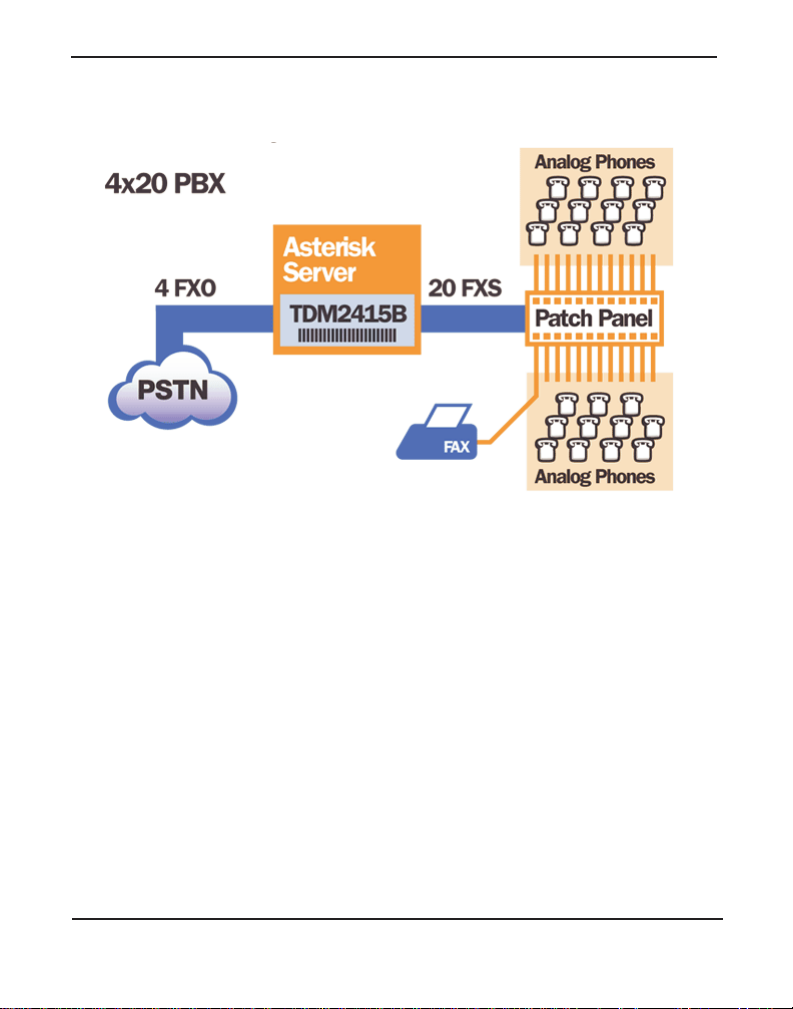
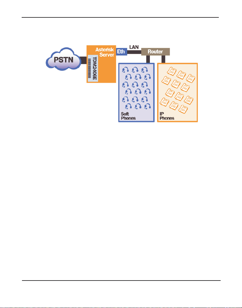
Figure 11: Sample Application
Note: More detailed information is provided at the Asterisk website
(www.asterisk.org), as well as the Digium Knowledge Base
(kb.digium.com). You may also obtain assistance by contact ing
Digium Technical Support (+1.256.428.6161) or visiting the website
at www.digium.com.
Digium, Inc. Page 49
Page 50

Chapter 4: FXS and FXO Explained
Chapter 4 FXS and FXO Explained
Identification
There are multiple standa rd conf igurations in which a 2400 Series card
may be purchased. Each configuration consists of one to six FXS and/or
FXO modules. These modules are identified by their color.
FXS - Foreign Exchange Station (Green Modules)
FXO - Foreign Exchange Office (Red Modules)
This chapter provides an in-depth review of the two module types and
their uses within your Aster isk server.
Note: Only qualified service personnel should install the card. Users
should not attempt to perform thi s function themselves.
FXS Module
The FXS module allows a 2400 Series card to initiate and send ringing
voltage to an FXO device such as an analog telephone.
FXO Module
The FXO module allows the 2400 Series card to terminate analog
telephone lines (POTS).
Digium, Inc. Page 50
Page 51

Chapter 4: FXS and FXO Explained
Because of the modular design, you can acti vate additional ports at any
time with more FXS or FXO daughter cards. The FXO module passes all
the call features any standard analog telephone line will support. The
phone receiving the call is the la st FXO device in the chain. When it
receives voltage from an FXS device, the pho ne rings.
Using Your 2400 Series Card
Connect an ou tside line to a n FXO port on your Asterisk server to receive
voltage from the outside line.
Connect phones to FXS ports on your Asterisk server. The recommended
maximum distance from an FXS module to its connected device is 1,500
ft. (457m). When the FXO module in your Asterisk Server receives the
voltage, it will then generat e voltage using the FXS module and send it t o
your analog phone.
Note: An analog phone line originating from an FXS module must
remain inside the same building as th e FXS module. In addition, an
analog phone line originating from an FXS module must not be
bundled with a line or lines t hat go outs ide the buildi ng where the F XS
module is located.
Caution.
FXS modules ar e not equipped with lightning protection and
should not be expos ed to high voltage. Lightning or high
voltage can cause damage to an FXS module. Damage caused
by lightning or high voltage will void the product warranty.
Digium, Inc. Page 51
Page 52

Chapter 5: Troubleshooting
Chapter 5 Troubleshooting
This chapter provides frequently asked questions and possible resolutions
as identified by Digium Technical Support. Multiple resources are
available t o obtai n mor e infor mation about Asterisk and Digium produc ts.
Please visit both www.digium.com and www.asterisk.org for more
information.
Digium, Inc. Page 52
Page 53

Chapter 5: Troubleshooting
The FXO module never seems to hang-up the line. How do I set it to
hang-up?
busydetect = yes and busycount = 10 in the chan_d ahdi.co nf for
Set
your channels. This will cause the line to hang-up by listening for a
consecutive number of busy tones. Upon editing
will need to restart Aster isk.
chan_dahdi.conf, you
I have echo problems on my FXO modules and I've tried the different
echo cancellation algorithms in dahdi_config.h, tried tweaking the
gains, and still nothing works. What can I do?
Run the fxotune utility with the -i option (fxotune -i 4). It should discove r
which DAHDI channels are FXO modules and tune them accordingly. Be
warned however , it takes a significant amount of time f or each module to
tune. A conservative estimate would be somewhere around 2-3 minutes
for each module. You only have to tune the channels once for each line.
The fxotune utility will store the calibration settings in /etc/fxotune.conf.
You will need to configure your system to run fxotune with the -s flag
(fxotune -s) during the Linux boot se quence in order to initialize the
previously discovered values which are stored in fxotune.conf. A
recommendation is to put ‘f xotune - s’ in y our distrib ution’s startup scripts
at some point after the DAHDI module loads and before Asterisk
executes.
Note: The digit after the -i option is the digit that will break dialtone
on the line.
There is a slight echo. How can I adjust the sound quality?
Digium, Inc. Page 53
Page 54

Chapter 5: Troubleshooting
There are several options available to correct this. Each involves editing
the
chan_dahdi.conf file. Be sure to restart Asterisk upon completion.
1. Adjust echocancel = yes to one of the following valu es: 32, 64, 128,
or 256
2. You can also s et
3. You can also ad j ust the
recommended to shift between -5 and 5.
How can I enable more features?
To view all of the options available to add to your dial plan, type the
following commands from within Aster isk:
*CLI> core show applications
*CLI> core show functions
Digium also offers ser vices to help configure and add features you might
need. Contact Digium Technical Support (+1.256.428.6161) for more
.
echotraining = yes.
rxgain and the txgain, although it is only
information.
Digium, Inc. Page 54
Page 55

Common Fixes
Chapter 5: Troubleshooting
1. Check t o see if the X Window System (e.g. X.Org Server) is running
by entering the following:
# ps aux | grep X
If the X Window System is running, stop the application since it may
cause a conflict with Asterisk.
2. C heck to see if your PATA IDE hard drives are running with DMA
levels set. Advance user can perform an
interface.
hdparm on your hard drive
Use hdparm with caut ion as t he man pa ge st ates that h ar d drive
corruptio n can occur when using incorrect settings. Please
review t he man page for hdp arm and mak e sur e you unde rst and
the risks before using thi s tool.
Check the current mode using this command:
hdparm -vi /dev/[IDE Device]
Use this command to set the drives into UDMA2 mode:
hdparm -d 1 -X udma2 -c 3 /dev/[IDE Device]
If you are still having problems, contact your reseller from which the
card was purchased, or Digium Technical Support (+1.256.428.6161).
Digium, Inc. Page 55
Page 56

Chapter 5: Troubleshooting
Where can I find answers to additional questions?
There are several places to inquire for more information about Asterisk
Digium products:
1. Digium Technical Support ( +1.256.428.6161), or T oll Free in the U.S.
(1.877.344.4861), is available 7am-8pm Central Time (GMT -6),
Monday - Friday.
2. Asterisk users mailing list (asterisk.org/lists.digium.com).
3. IRC channel
Subscription Services Program
Digium is dedicated to support ing your Asterisk system by offeri ng full
technical support through our Subscription Services Program. Through
this program, you can be at ease knowing that your business will always
have access to the Asterisk expert s. Prici ng on Subscription Servic es may
be obtained from your nearest reseller or you may call Digium Sales for
referral to your neares t rese ller at +1.256.428.6000 or e-mail
sales@digium.com.
#asterisk on (irc.freenode.net).
Digium, Inc. Page 56
Page 57

Appendix A
50 25
26
1
Pins 25 & 50, Not Used
Pins 24 & 49, Port 24, Slot 6
Pins 23 & 48, Port 23, Slot 6
Pins 22 & 47, Port 22, Slot 6
Pins 21 & 46, Port 21, Slot 6
Pins 20 & 45, Port 20, Slot 5
Pins 19 & 44, Port 19, Slot 5
Pins 18 & 43, Port 18, Slot 5
Pins 17 & 42, Port 17, Slot 5
Pins 16 & 41, Port 16, Slot 4
Pins 15 & 40, Port 15, Slot 4
Pins 14 & 39, Port 14, Slot 4
Pins 13 & 38, Port 13, Slot 4
Pins 12 & 37, Port 12, Slot 3
Pins 11 & 36, Port 11, Slot 3
Pins 10 & 35, Port 10, Slot 3
Pins 9 & 34, Port 9, Slot 3
Pins 8 & 33, Port 8, Slot 2
Pins 7 & 32, Port 7, Slot 2
Pins 6 & 31, Port 6, Slot 2
Pins 5 & 30, Port 5, Slot 2
Pins 4 & 29, Port 4, Slot 1
Pins 3 & 28, Port 3, Slot 1
Pins 2 & 27, Port 2, Slot 1
Pin Assignments
Appendix A: Pin Assignments
The 2400 Series car d provides a 50-pin R J21 connec tor for FXO and FXS
access.
Figure A-1: RJ-21 Port Connector
Note: Pins 1-24 are ‘tip’ for channels 1-24. Pins 26-49 are ‘ring’ for
channels 1-24.
Digium, Inc. Page 57
Page 58

Appendix B Specifications
Appendix B: Specifications
This appendix provides specifications, required environmental
conditions, and maximum power consumption for the 2400 Series
cards.
Physical.
Size: 12.28” × 4.2” × 0.68” (31.19 x 10.67 x 1.72 cm)
PCB size, does not include the PCI bracket or retainer.
W e ight: 5.8 oz (164.43gm) with no modules loaded. Each quad
module adds 1 oz (28.3gm)
Interfaces.
Local Loop Access: Industry standard 50-pin RJ-21 (amphenol).
Note: RJ-21 cables and patch panels are available from Digium.
FXS modules are not equipped with lightning pr otection and should
not be exposed to high voltage. Lightning or high voltage can cause
damage to an FXS module. Damage caused by lightning or high
voltage will void the product warr anty .
The recommended maximum distance from an FXS module to its
connected device is 1,500 ft. (457m).
PCI Bus (TDM2400P): 3.3V or 5V bus slot, full length full height,
33MHz minimum bus speed, compliant with PCI 2.2 or greater.
Digium, Inc. Page 58
Page 59

Appendix B: Specifications
(AEX2400) - PC I-E X1, compliant with PCI-E X1 1.0 or greater.
Additional Power: Four-pin 12V connector for FXS power supply
(required only if FXS modules are installed)
Environment.
Temperature: 0 to 50° C (32 to 122° F) operation
-20 to 70° C (4 to 158° F) storage
Humidity: 10 to 90% non-condensing
Note: Operating temperature is limite d to 0 to 40° C (32 to 104° F)
when used with optional PWR2400B Power Bracket.
Hardware an d Softw a re Requirements.
800-Mhz Pentium III or better
64MB RAM
Available PCI or PCI-Express Slot (as described previously)
Digium, Inc. Page 59
Page 60

Appendix B: Specifications
Table B-1: Maximum Power Consumption
Model Power
3.3V All TDM models
3.3V All AEX “B” models
3.3V All AEX “E” models
5V All TDM models
5V All AEX models
12V AEX/TDM2406E
into 1REN
12V AEX/TDM2433E
into 2REN
12V AEX/TDM2433E
into 3REN
12V AEX/TDM2433E
into 4REN
12V AEX/TDM2433E
into 5REN
1.0 Watt
4.0 Watts
4.7 Watts
9.0 Watts
0.0 Watts
11. 0 Wat t
12.0 Watts
15.0 Watts
17.5 Watts
20.0 Watts
Digium, Inc. Page 60
Page 61

Appendix C
Appendix C: Glossary and Acronyms
Gloss ary and Acronyms
ANSI American National Standards Institute
An organization which proposes and establishes standards for
international communications.
asynchronous
Not synchronized; not timed to an outside clock source. Transmi ssion is
controlled by start bits a t the beginning and stop bits at the end of each
character. Asynchronous communic a tions are often found in internet
access and remote office applications.
attenuation
The dissipation of a transmitted signal’s power as it travels over a wire.
bandwidth
The capacity to carry traffic. Higher bandwidth indicates the ability to
transfer more data in a given time period.
bit
The smallest element of information in a digital system. A bit can be
either a zero or a one.
bps bits per second
A measurement of transmission spe ed across a data connection.
Digium, Inc. Page 61
Page 62

broadband
Appendix C: Glossary and Acronyms
Broadband transmission sha res the bandwidth of a particular medium
(copper or fiber optic) to integrate multiple signals. The channels take up
different f requencies on the cable, integrat ing voice, data, and video over
one line.
channel
A generic term for an individual dat a stre am. Ser vice providers can use
multiplexing techniques to transmit multiple channels over a common
medium.
Cat5
Category of Performance for wiring a nd cabling. Cat 5 cabling support
applications up to 100 MHz.
Cat5E
Category of Performance for wiring a nd cabling. Category 5 Enhanced
wiring supports signal r ates up to 100 MHz but adheres to stricter quality
specifications.
CLEC competitive local exchange carrier
A term for telephone companies established after the
T elecommunications Act of 1996 deregulated the LECs. CLECs compete
with ILECs to offer local service. See als o LEC and ILEC.
Digium, Inc. Page 62
Page 63

CO central office
Appendix C: Glossary and Acronyms
The CO houses local switching equipment. All local access lines in a
particular geographic area terminate at this facility (which is usually
owned and operated by an ILEC).
CPE customer prem ises equipm ent
T erminal equipment which is connected to the telecommunications
network and which resides within the home or of fice of the customer . This
includes telephones, modems, terminals, routers, and television set-top
boxes.
DAHDI Digium Asterisk Hardware Device Interface
A telephony project dedicated to implementing a reasonable and
affordable compute r te lephony plat form in to t he wor ld mar ketpla ce. Al so,
the collective name for the Digium -provided drivers for Digium
telephony interface products.
DS0 Digital Signal, Level 0
A voice grade channel of 64 Kbps. The worldwide standar d speed for
digitizing voice conversation using PCM (Pulse Code Modulation).
DS1 Digital Signal, Level 1
1.544 Mbps in North America (T1) and Japan (J1) -up to 24 voice
channels (DS0s), 2.048 Mbps in Europe (E1) - up to 32 voice channels
(DS0s). DS1/T1/E1 lines are part of the PSTN.
Digium, Inc. Page 63
Page 64

Appendix C: Glossary and Acronyms
DS3 Digital Signal, Level 3
T3 in North America and Japan, E3 in Europe. Up to 672 voice channels
(DS0s). DS3/T3/E3 lines are not part of the PSTN
DTMF Dual Tone Multi-Frequency
Push-button or touch tone dial ing.
E1
The European equivalent of North Ameri can T1, transmits data at 2.048
Mbps, up to 32 voice channels (DS0s).
E3
The European equival ent of North American T3, transmits data at 34.368
Mbps, up to 512 voice channels (DS0s). Equivale nt to 16 E1 lines.
EMI Electromagnetic Interference
Unwanted electrical noise present on a power line
full duplex
Data transmission in two directions simultaneously.
FXO Foreign Exchange Office
Receives the ringing voltage from an FXS device. Outside lines are
connected to the FXO port on your 2400 Series card.
Digium, Inc. Page 64
Page 65

FXS Foreign Exchange Station
Appendix C: Glossary and Acronyms
Initiates a nd sends ringin g vol tage. P hones ar e c onnected to t he FXS ports
on the 2400 Series card.
G.711
A recommendation by the Telecommunication Standardization Sector
(ITU-T) for an algorithm designe d to transmit and receive mulaw PCM
voice and A-law at a digita l bit rate of 64 Kbps. This algor ithm is used fo r
digital telephone sets on digital PBX.
G.723.1
A recommendation by the Telecommunication Standardization Sector
(ITU-T) for an algorithm designe d to transmit and receive audio over
telephone lines at 6.3 Kbps or 5.3 Kbps.
G.729a
A recommendation by the Telecommunication Standardization Sector
(ITU-T) for an algorithm designe d to transmit and receive audio over
telephone lines at 8 Kbps.
H.323
A recommendation by the Telecommunication Standardization Sector
(ITU-T) for multimedia communic ations over packet-based networks.
IAX Inter-Asterisk eXchange
The native VoIP protocol used by Asterisk. It is an IETF standard used to
enable VoIP connections between Asterisk ser vers, a nd between servers
and clients that also use the IAX protoc ol.
Digium, Inc. Page 65
Page 66

iLBC internet Low Bitrate Codec
Appendix C: Glossary and Acronyms
A free speech codec used for voice over IP. It is designed for narrow band
speech with a payload bitrate of 13.33 kbps (frame length = 30ms) and
15.2 kbps (frame length = 20 ms).
ILEC incumbent local exchange c arrier
The LECs that were the or iginal carr iers in the market pr ior to th e entry of
competition and theref ore have the dominant position in the market.
interface
A point of contact between two systems, networks, or devices.
ISO International Standards Organization
LED light-emitting diode
Linux
A robust, feature-packed open source operating system based on Unix
that remains freely available on the internet. It boasts dependa bility and
offers a wide range of compatibility with hardware and software. Asterisk
is supported exclusively on Linux.
loopback
A state in which the transmit sig nal i s reversed back as the receive si gnal,
typically by a far end network element.
Digium, Inc. Page 66
Page 67

Appendix C: Glossary and Acronyms
MGCP M edia Gateway Cont rol Protocol
multiplexing
Transmitting multiple signals over a single line or channel. FDM
(frequency divisi on multiplexing) and TDM (time division multiplexing)
are the two most common methods. FDM separates signals by dividing
the data onto different carrier frequencies, and TDM separates signals by
interleaving bit s one after the other.
MUX multiplexer
A device which transmits multipl e signals over a single communications
line or channel. See multiplexing.
PBX private branch exchange
A smaller version of a phone company’s large centr al switching office.
Example: Asterisk.
PCI peripheral component interconn ect
A standard bus used in most computers to connect per iphe ral devices.
POP point of presence
The physical connection point between a network and a telephone
network. A POP is usually a network node serving as the equivalent of a
CO to a network service provider or an interexchange carrier.
POTS plain old telephone service
The public switched teleph one network (PSTN) is the network of the
world's public circui t-switched telephone networks. Originally a network
Digium, Inc. Page 67
Page 68

Appendix C: Glossary and Acronyms
of fixed-line analog te lephone systems, the PSTN is now almost entirely
digital, and now includes mobile as well as fixed telephones.
PPP point-to-point protocol
Type of communications link that connects a single device to another
single device, such as a remote terminal to a host computer.
PSTN public switched telephone network
A communications network which uses telephones to establish
connections between two poin ts. Also r eferred to as the dial network.
QoS quality of service
A measure of telephone service, as spe cified by the Public Service
Commission.
RJ11
A six-pin ja ck typically used f or connecting telephones, modems, and fax
machines in residentia l and business settings to PBX or the local
telephone CO.
SIP Session Initiation Protocol
An IETF standard for setting up sessions be tween one or more clients. It
is currently the leading signaling protocol for Voice over IP, gradually
replacing H.323.
Digium, Inc. Page 68
Page 69

T1
Appendix C: Glossary and Acronyms
A dedicated digital carrier facility which transmits up to 24 voice
channels (DS0s) and transmit s data at 1.544 Mbps. Commonly used to
carry traff ic to and from priva te business networks and ISPs.
T3
A dedicated digital carrie r fa cility which consists of 28 T1 lines and
transmits data at 44.736 Mbps. Equivalent to 672 voice channels (DS0s).
TDM time division multiplexer
A device that supports simul taneous transmissi on of multiple data streams
into a single high-speed dat a stre am. TDM separa tes signals by
interleaving bit s one after the other.
telco
A generic name which refers to the telephone companies throughout the
world, including RBOCs, LECs, and PTTs.
tip and ring
The standard terminati on on the two conduct ors of a telephone circuit;
named after the physical appear a nce of the contact areas on the jack plug.
twisted pair
T wo copper wires commonly used for telephony and data
communications. The wires are wrapped loosely around each other to
minimize radio frequency interference or interference from other pairs in
the same bundle.
Digium, Inc. Page 69
Page 70

V volts
VoIP Voice over IP
Appendix C: Glossary and Acronyms
T echnology used for transmitting voice traffic over a data network using
the Internet Protoco l.
Digium, Inc. Page 70
 Loading...