

Page 1

Asterisk Appliance™ 50
(AA50)
Administrator Manual
601-00005 Rev. C
Page 2

445 Jan Davis Drive
Digium, Inc.
Huntsvil le, AL 35806
United States
Main Number: 1.256. 428.6000
Tech Support : 1.256.428.6161
U.S. Toll Free: 1.877.344.4861
Sales: 1.256.428.6262
www.digium.com
www.asterisk.org
www.asterisknow.org
© Digium, Inc. 2009
All rights reserved.
No part of this publication may be copied, distributed, transmitted, transcribed, stored in a
retri eval syst em , or t ran sl ated int o any huma n or compu te r lan gu ag e with ou t t he pr io r wri tte n
permission of Digium, Inc.
Digium, Inc. has made every effort to ensure that the instructions contained in this document
are ade q u a te an d error fr ee . The ma nu f a ctu r e r w i ll, if nec es s ar y , ex plain is su es w h ic h m ay
not be covered by this documentation. The manufacturer’s liability for any errors in the
docume nt is limited to the correction of errors and the aforementioned advisor y services.
This doc ument has been prepar ed for us e by profe ssiona l and pr operly tr ained personn el,
and the cus to m er as su m es full respon si bi li t y whe n us ing it.
Adobe and Acrobat are registered trademarks, and Acrobat Reader is a trademark of Adobe
Systems Incorporated.
Asteri sk and D igi um a r e re gi ster e d tr ad emar ks and Ast eri sk B usi ne ss Ed it i on, A st eri sk NOW,
AsteriskGUI, an d Asterisk Appliance 50 are trademarks of D igium, Inc.
Any other trademarks mentioned in the document are the property of their respective owners.
Digium, Inc. Page 2
Page 3

Safety Certificat ion and Agency Approvals
Safety:
US/CSA 60950
IEC 60950
EN 60950
AS/NZ 60950
Other:
CE Mark (European Union)
2002/95/EC Restr ictions on Hazardous S ubst ances (Ro HS), 2005/ 747/EC
lead free exemption (Annex C)
Telecom:
FCC Part 68, TIA-968
TBR-21 1998
Industry Canada IC-CS-03
AS-ACIF S002-2005
AS-ACIF S003-2005
EMC:
FCC Part 15 Class A
EN55022/CISPR22 Class A
EN55025
IEC 61000
CNS13438
VCCI V-32005.04
Digium, Inc. Page 3
Page 4

Federal Communications Commission Part 68 (USA)
This equipment complies with Part 68 of the FCC rules and the
requirements adopted by the ACTA. On the back of the Asterisk
Appliance 50 enclosur e is a label that contains, among other information,
a product identifier in the format US:AAAEQ##TXXXX. If requested,
this number must be provided to the teleph one company.
A plug and jack used to connect this equipment to the premi ses wiring
and telephone network must comply with the applicable FCC Part 68
rules and requirements adopted by the ACTA.
If the Asterisk Appliance 50 causes har m to the telephone network, the
telephone company may notify you in advance that temporary
discontinuance of service may be required. But if advance notice is not
practical, the telephone company will notify you as soon as possible.
Also, you will be advised of your right to file a complaint with the FCC if
you believe it is necessary.
The telephone company may make changes in its facilities, equipment,
operations or procedures that could a ffect the operation of the equipment.
If this happens, the telephone company will provide advance notice in
order for you to make necessary modifications to maintain uninterrupted
service.
If you experience problems with the Asterisk Appliance 50, contact
Digium, Inc. (+1.256.428.6161) for repa ir and/or war ranty inf ormatio n. If
the equipment is causing harm to the telephone network, the telephone
company may request that you disconnect the equipment until the
problem is resolved.
Digium, Inc. Page 4
Page 5

FCC Part 15
This device complies with part 15 of FCC rules. Operation is subject to
the following two conditions: (1) This device may not cause harmful
interferen ce, and (2) T h is dev ice mu s t accep t any in terference received ,
including interf erence that may cause undesired operation.
Digium, Inc. Page 5
Page 6

Introduction to Asterisk Appliance 50 Documentation
This manual contains product information for the Asterisk Appliance 50.
Be sure to refer to any supplementary documents or release notes that
were shipped with your equipment. The manual is organized in the
following manner:
Chapter/
Appendix
1
2
3
4
A
B
C
D
Title Description
Overview Identifies the features of your unit.
Unit Installation Provides instructions for installing the unit.
Asterisk
Configuration
Troublesh ooting Explain s resolutions to common problems and
Pin Assignments Lists the connectors and pin assignments .
Specifications Details unit specifications.
License Agreeme nt Digium End-User Purchase and Li cens e Agreement
Glossary and
Acronyms
Provide s instructions on how to configure the
Embedded Asterisk Business Edition through the use
of the AsteriskGUI.
frequentl y as ked questions pertaining to the unit.
Defines terms related to this product.
Digium, Inc. Page 6
Page 7

Symbol Definitions
Caution stat emen ts in dicate a c onditio n whe r e d amage to t he un it o r
its configuration could occur if operational procedures are not
followed. To reduce the risk of damage or injury, follow all steps or
procedures as instructed.
The ESD sym b o l in d i ca t es electrostat i c sen si ti ve device s. O b serve
prec autions for handling devi ces. Wear a proper ly grounded
electrostatic discha rge (ESD) wrist strap while handling the device.
The Electrical Hazard Symbol indicates a possibility of electrical
shock when operat ing this unit in certain situations. To reduce the
risk of damage or injury, fol low all steps or proc edures as
instructed.
Digium, Inc. Page 7
Page 8

Important Safety Instructions
Servicing.
Do not attempt to servi ce this unit un less s pecif ic ally ins truc ted to do
so. Do not attempt to remove the unit from your equipment while
power is present. Refe r ser vicing to qualified service personnel.
Water and Moisture.
Do not spill liquids on this unit. Do not operate this equipment in a
wet environme nt.
Heat.
Do not operate or store this product near heat sources such as
radiators, air ducts, areas subject to direct, intense sunlight, or other
products that produce heat.
Warning.
Do not place anythi ng (including paper) on top of the Asterisk
Appliance 50. To allow proper cooling, these units must not be
stacked.
Caution.
To reduce the risk of fire, use only No. 26 AWG or larger
telecommunication wiring for network connections.
Static Electricity.
To reduce the risk of damaging the unit or your equipment, do not
attempt to open the enclosur e or gain acc es s to areas where you ar e
not instructed to do so. Refer servicing to qualified service personnel.
Emergency 911
The Asterisk Appliance 50 is capable of forwarding arbitrary caller
id strings to VoIP service providers, which in multi-office setups
could simply be other Asterisk Appliance 50s. Customers of Internet
Telephony Service providers to which 91 1 or Emergency calls are
placed shou ld ens ur e the ir pr o vid er pr o perl y forw ar ds t he cus tomer 's
accessibl e PSTN phone number to the emergency call handling
center.
Save these instructions for future reference.
Digium, Inc. Page 8
Page 9

TABLE OF CONTENTS
Introduction to Asterisk Applia n ce 50 Docume nt a tion . . . . . . . . . . .6
Chapter 1
Overview . . . . . . . . . . . . . . . . . . . . . . . . . . . . . . . . . . . . . . . . . . . . . . . 15
Features: . . . . . . . . . . . . . . . . . . . . . . . . . . . . . . . . . . . . . . . . . . . . .16
Chapter 2
Unit Installation . . . . . . . . . . . . . . . . . . . . . . . . . . . . . . . . . . . . . . . . . .17
Unpacking the Unit . . . . . . . . . . . . . . . . . . . . . . . . . . . . . . . . . . . . .18
Inspecting Your Shipment . . . . . . . . . . . . . . . . . . . . . . . . . . . . . . . . 18
Identifying Communication Ports . . . . . . . . . . . . . . . . . . . . . . . . . .19
Understanding the LEDs . . . . . . . . . . . . . . . . . . . . . . . . . . . . . . . . .19
Using the Configuration Reset Switch . . . . . . . . . . . . . . . . . . . . . . 23
Installing the Asterisk Appliance 50 . . . . . . . . . . . . . . . . . . . . . . . . 24
Mounting the Asterisk Appliance 50 . . . . . . . . . . . . . . . . . . . . . . . . 27
Chapter 3
Telephone System Configuration . . . . . . . . . . . . . . . . . . . . . . . . . . .29
Log On to the Asterisk Appliance 50 . . . . . . . . . . . . . . . . . . . . . . . .31
The Asteris k Appl iance 50 Interface . . . . . . . . . . . . . . . . . . . . . . . .32
Analog Hardware Conf i gura tion . . . . . . . . . . . . . . . . . . . . . . . . . . .35
Trunk Configuration . . . . . . . . . . . . . . . . . . . . . . . . . . . . . . . . . . . .40
Analog Trunks . . . . . . . . . . . . . . . . . . . . . . . . . . . . . . . . . . . . . . . . .41
Outgoing Ca lling Rules . . . . . . . . . . . . . . . . . . . . . . . . . . . . . . . . . .55
Dial Plans . . . . . . . . . . . . . . . . . . . . . . . . . . . . . . . . . . . . . . . . . . . .59
Digiu m, In c . Page 9
Page 10

Table Of Contents
User Extensions . . . . . . . . . . . . . . . . . . . . . . . . . . . . . . . . . . . . . . .61
Ring Groups . . . . . . . . . . . . . . . . . . . . . . . . . . . . . . . . . . . . . . . . . .68
Music on Hold . . . . . . . . . . . . . . . . . . . . . . . . . . . . . . . . . . . . . . . . .70
Call Queues . . . . . . . . . . . . . . . . . . . . . . . . . . . . . . . . . . . . . . . . . .72
Agent Login Settings . . . . . . . . . . . . . . . . . . . . . . . . . . . . . . . . . . . .77
Voice Menus . . . . . . . . . . . . . . . . . . . . . . . . . . . . . . . . . . . . . . . . . .78
Record a Voice Menu . . . . . . . . . . . . . . . . . . . . . . . . . . . . . . . . . . . 85
Time Intervals . . . . . . . . . . . . . . . . . . . . . . . . . . . . . . . . . . . . . . . . .87
Incomi ng Ca lling Rules . . . . . . . . . . . . . . . . . . . . . . . . . . . . . . . . . .89
Voicemail . . . . . . . . . . . . . . . . . . . . . . . . . . . . . . . . . . . . . . . . . . . .93
Paging/Intercom . . . . . . . . . . . . . . . . . . . . . . . . . . . . . . . . . . . . . . . 97
Conferencing . . . . . . . . . . . . . . . . . . . . . . . . . . . . . . . . . . . . . . . . 1 01
Follow Me . . . . . . . . . . . . . . . . . . . . . . . . . . . . . . . . . . . . . . . . . . .104
Directory . . . . . . . . . . . . . . . . . . . . . . . . . . . . . . . . . . . . . . . . . . . .110
Call Features . . . . . . . . . . . . . . . . . . . . . . . . . . . . . . . . . . . . . . . . 1 12
Voicemail Groups . . . . . . . . . . . . . . . . . . . . . . . . . . . . . . . . . . . . .122
System Info . . . . . . . . . . . . . . . . . . . . . . . . . . . . . . . . . . . . . . . . . .123
Networking . . . . . . . . . . . . . . . . . . . . . . . . . . . . . . . . . . . . . . . . . .124
G.729 Codec . . . . . . . . . . . . . . . . . . . . . . . . . . . . . . . . . . . . . . . . .1 27
Backup . . . . . . . . . . . . . . . . . . . . . . . . . . . . . . . . . . . . . . . . . . . . . 1 30
Update . . . . . . . . . . . . . . . . . . . . . . . . . . . . . . . . . . . . . . . . . . . . .1 31
Options . . . . . . . . . . . . . . . . . . . . . . . . . . . . . . . . . . . . . . . . . . . . . 1 34
Chapter 4
Troubleshooting . . . . . . . . . . . . . . . . . . . . . . . . . . . . . . . . . . . . . . . .1 40
Appendix A
Digium, Inc. Page 10
Page 11

Table Of Contents
Pin Assignments . . . . . . . . . . . . . . . . . . . . . . . . . . . . . . . . . . . . . . . .141
Appendix B
Specifications . . . . . . . . . . . . . . . . . . . . . . . . . . . . . . . . . . . . . . . . . .145
Appendix C
Asterisk Appliance 50 (AA50) License Agreement . . . . . . . . . . . .147
Appendix D
Glossary and Acronyms . . . . . . . . . . . . . . . . . . . . . . . . . . . . . . . . . .208
Digium, Inc. Page 11
Page 12

List of Figures
Figure 1: The Asteris k Appl iance 50 (AA50) . . . . . . . . . . . . . .17
Figure 2: Example Asterisk Appliance 50 Port Identification . .22
Figure 3 : Asterisk Appliance 50 Back View . . . . . . . . . . . . . . .24
Figure 4 : Mounting Instructions . . . . . . . . . . . . . . . . . . . . . . . .27
Figure 5: GUI Login . . . . . . . . . . . . . . . . . . . . . . . . . . . . . . . . . 31
Figure 6 : System Status Page . . . . . . . . . . . . . . . . . . . . . . . . .32
Figure 7 : Configure Hardware . . . . . . . . . . . . . . . . . . . . . . . . .35
Figure 8 : Trunk Configuration Page . . . . . . . . . . . . . . . . . . . . .40
Figure 9 : New Analog Trunk Definition . . . . . . . . . . . . . . . . . . 41
Figure 10: Edit Analog Trunk Definition . . . . . . . . . . . . . . . . . . .45
Figure 1 1: Add New Service Provider . . . . . . . . . . . . . . . . . . . .47
Figure 1 2: Edit VoIP Service Provider . . . . . . . . . . . . . . . . . . . . 48
Figure 1 3: Create New SIP/IAX Trunk Definition . . . . . . . . . . . .50
Figure 14: Ed it VoIP Trunk . . . . . . . . . . . . . . . . . . . . . . . . . . . . .52
Figure 15: Outbound Calling Rules . . . . . . . . . . . . . . . . . . . . . .55
Figure 16: New Calling Rule . . . . . . . . . . . . . . . . . . . . . . . . . . .56
Figure 1 7: Create New Dial Plan . . . . . . . . . . . . . . . . . . . . . . . .59
Figure 18: Use r Exte n sions . . . . . . . . . . . . . . . . . . . . . . . . . . . .61
Figure 19: Cre a te New User . . . . . . . . . . . . . . . . . . . . . . . . . . .62
Figure 2 0: New Ring Group . . . . . . . . . . . . . . . . . . . . . . . . . . . .68
Figure 21: Music on Hold . . . . . . . . . . . . . . . . . . . . . . . . . . . . . .70
Figure 22: New Call Queue . . . . . . . . . . . . . . . . . . . . . . . . . . . . 72
Figure 2 3: Default Voice Menu . . . . . . . . . . . . . . . . . . . . . . . . .78
Figure 2 4: Custom Voice Menu Prompts Page . . . . . . . . . . . . .85
Figure 2 5: Record Menu Prompts . . . . . . . . . . . . . . . . . . . . . . .85
Figure 26: Up load Menu Prompts . . . . . . . . . . . . . . . . . . . . . . .86
Figure 2 7: New Time Interval . . . . . . . . . . . . . . . . . . . . . . . . . . .87
Figure 28: Incoming Calling Rules . . . . . . . . . . . . . . . . . . . . . . .89
Digium, Inc. Page 12
Page 13

List of Figures
Figure 29: Incoming Calling Rules . . . . . . . . . . . . . . . . . . . . . . .90
Figure 3 0: Voicemail . . . . . . . . . . . . . . . . . . . . . . . . . . . . . . . . .93
Figure 3 1: Paging/Intercom . . . . . . . . . . . . . . . . . . . . . . . . . . . .97
Figure 32: New Page/Intercom Group . . . . . . . . . . . . . . . . . . . .98
Figure 3 3: Settings for Paging Individual Extensions . . . . . . . . .99
Figure 3 4: Paging & Intercom Settings . . . . . . . . . . . . . . . . . . 1 00
Figure 3 5: New Conference Bridge . . . . . . . . . . . . . . . . . . . . .101
Figure 3 6: Follow Me . . . . . . . . . . . . . . . . . . . . . . . . . . . . . . . . 1 04
Figure 37: New Follow Me Definition . . . . . . . . . . . . . . . . . . . .106
Figure 3 8: Follow Me Options . . . . . . . . . . . . . . . . . . . . . . . . .108
Figure 3 9: Directory Settings . . . . . . . . . . . . . . . . . . . . . . . . . .110
Figure 4 0: Feature Codes . . . . . . . . . . . . . . . . . . . . . . . . . . . .112
Figure 4 1: Call Parking Preferences . . . . . . . . . . . . . . . . . . . .116
Figure 4 2: Application Map . . . . . . . . . . . . . . . . . . . . . . . . . . .1 18
Figure 4 3: Dial Options . . . . . . . . . . . . . . . . . . . . . . . . . . . . . .120
Figure 4 4: New Voicemail Group . . . . . . . . . . . . . . . . . . . . . . .122
Figure 4 5: System Information . . . . . . . . . . . . . . . . . . . . . . . . .1 23
Figure 4 6: Networking . . . . . . . . . . . . . . . . . . . . . . . . . . . . . . .124
Figure 4 7: G.729 Codec Registration . . . . . . . . . . . . . . . . . . .127
Figure 4 8: G.729 Codec License Information . . . . . . . . . . . . .1 28
Figure 4 9: Backup Page . . . . . . . . . . . . . . . . . . . . . . . . . . . . .130
Figure 5 0: Asterisk Appliance 50 Update . . . . . . . . . . . . . . . . .1 31
Figure 5 1: Polycom Update . . . . . . . . . . . . . . . . . . . . . . . . . . .132
Figure 5 2: Asterisk Appliance 50 Options . . . . . . . . . . . . . . . . 1 34
Figure A-1: Back Panel Ports . . . . . . . . . . . . . . . . . . . . . . . . . . 141
Digium, Inc. Page 13
Page 14

List of Tabl e s
Table A-1: CRAFT Port Pinout . . . . . . . . . . . . . . . . . . . . . . . . .142
Table A-2: RJ11 Analog Port Connector. . . . . . . . . . . . . . . . . .1 43
Table A-3: LAN & WAN Ethernet Port Pinouts . . . . . . . . . . . . .144
Table B-4: Maximum 12V Power Consumption . . . . . . . . . . . . 1 46
Digium, Inc. Page 14
Page 15

Chapter 1 Overview
The Digium® Asterisk Appliance 50 (AA50) is a stand alone PBX which
runs Embedded Asterisk Business Edition™. It is suitable for the desktop,
or mounting in a typical network closet or restricted access location. The
Asterisk Appliance 50 is ideal for small office environments or as an
extension to a central Asterisk PBX.
The Asterisk Appliance 50 can funct ion not only as a PBX, but also as a
voice mail server, IVR server, conferencing server, VoIP ATA, or VoIP
gateway. It has up to eight analog ports which are configur ed as FXO or
FXS ports depending upon the product model. Additionally, the built in
four port switch and WAN port allow it to also serve as a basic router.
The AsteriskGUI™ is the in terface f or the Asteris k Applia nce 50. I t gives
you the ability to conf igure the basic har dware and dia l plan elemen ts you
need when initially setting up your system, as well as every element
needed to customize your setup. You must create trunks, system users,
conferencing, voice mail, etc. The AsteriskGUI supports the following
browsers:
Firefox 1.5 through 3.0
IE 7
Safari 3.x
Opera 9.x
Digiu m, In c . Page 15
Page 16

Chapter 1: Overview
Features:
Embedded Asterisk Business Edition™
AsteriskGUI™
Four port 10/100BaseT Ethernet switch with Auto-MDI/MDI-X capa-
bility for the four 10/100Base T LAN ports and one
10/100baseT WAN port (both 802.3/802.3u)
Up to eight analog ports supporting either FXS or FXO lines depend-
ing on product version (available product versions: S800i with VoIP
only , S80 8i with Eight FXO, and S844i with Four FXS and Four FXO)
SIP and IAX2 VoIP protocols
CompactFlash interfa ce (Type 1) suitable for standard CompactFlash
cards
Configuration reset switch
High performance Analog Devices Incorporated (ADI) BlackFin
BF537 processor
uClinux Operating System
Transcoding provided on the Blackfin processor
32ms (Hardware R evision B) or 128ms (Hardware Revision C) of ana-
log port echo cancellation
8MB on board serial Flash memory
64MB 16 bit parallel SDRAM
Fron t panel LE Ds
Digium, Inc. Page 16
Page 17

Chapter 2 Unit Installation
This chapter provides the following information:
Unpacking the Unit on page 18
Inspecting Your Shipment on page 18
Identifyi ng C om m un ic a tion Por ts on page 19
Underst andi n g th e LEDs on page 19
Using the Configuration Reset Switch on page 23
Installin g the A st eris k Appliance 50 on page 24
Mounting the Asterisk Appliance 50 on page 27
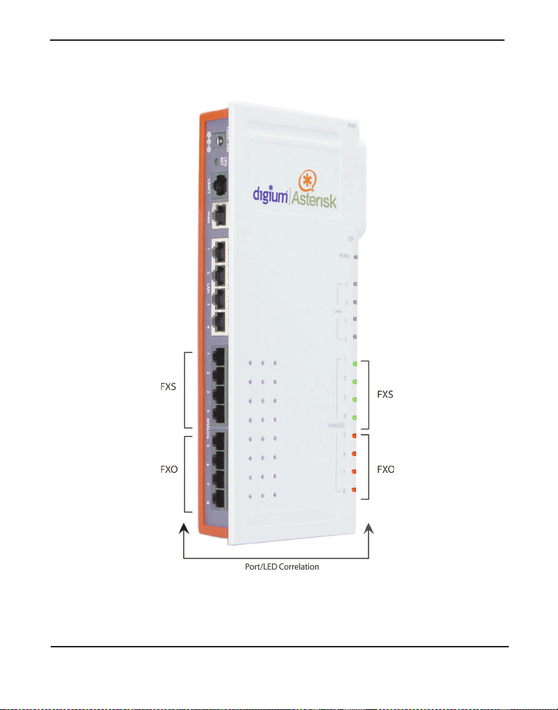
Figure 1: The Asterisk Appliance 50 (AA50)
Digiu m, In c . Page 17
Page 18

Chapter 2: Unit Installation
Unpacking the Unit
When you unpack your unit, carefully inspect it for any damage that m ay
have occurred during shipmen t. If damage is suspected, file a claim with
the carrier and contact your resell er from which the unit was purcha sed or
Digium T ec hnical Support (+1. 256.428. 6161). Keep the origina l shi pping
container to use for future shipment or proof of damage during shipment.
Note: Only qualified service personnel should install the unit. Users
should not attempt to perform thi s function themselves.
Inspecting Your Shipment
The following items are includ ed in shipment of the Asterisk Appliance
50:
Asterisk Appliance 50 (AA50)
Compact Fl ash Card
Power Supply
Power Cable
Analog Cables (optional depending on model)
CD-ROM containing manual and installa tion files
Product Registration Card
Support and Warranty Information
Digium, Inc. Page 18
Page 19

Chapter 2: Unit Installation
Identifyi ng C om m un ic a tion Por ts
The Asterisk Appliance 50 unit consists of up to eight RJ11 analog ports
which are configured as FXO or FXS ports depending on the Asterisk
Appliance 50 model. These ports provide 32ms (Hardware Revisions B)
or 128ms (Hardware Revisions C) of analog por t echo canc ellation. The
unit is rated for a total of 8 REN across all FXS ports. Each individual
port is rated for up to 3 REN @ 1500ft (450m).
Four 10/100BaseT LAN ports and one 10/100BaseT WAN port provide
the functionality to connect to the local network as well as allowing the
Asterisk Appliance 50 to act as a router. All the Ethernet ports support
auto-MDI-X.
See Figure 2 on page 22 to locate th e ports and their cor responding LEDs .
Underst andi n g th e LEDs
There are 15 LEDs on the front panel of the Asterisk Appliance 50. The
eight LEDs corresponding to the analog ports on the rear panel indicate
the type of interface installed. The definition of each LED and its color
representation is explained in Table 1.
Digium, Inc. Page 19
Page 20

Chapter 2: Unit Installation
Table 1: LED Definitions
LED Color Description
Power Blue
(pulsing)
On when the unit boots up, after the
bootload process has c omplete d. The LE D
pulses at a rate which is proporti onal to the
processor load.
Compact
Flash
Blue
(flashing)
Flashes each time there is read or write
activity to or from the CompactFlash card.
WAN Off No line is connected or the interface is
inactive.
LAN
(4 ports)
Green
(flashing)
Orange
(flashing)
Off No line is connected or the interface is
Green
(flashing)
Orange
(flashing)
Link is up at 100Mbps. LED flashes at 1/
10 second intervals as traffic is detected.
Link is up at 10Mbps. LED flashes at 1/10
second intervals as traffic is detected.
inactive.
Link is up at 100Mbps. LED flashes at 1/
10 second intervals as traffic is detected.
Link is up at 10Mbps. LED flashes at 1/10
second intervals as traffic is detected.
Digium, Inc. Page 20
Page 21

Chapter 2: Unit Installation
Table 1: LED Definitions
LED Color Description
Analog
(8 ports)
Off No analog port is installed in the
corresponding port.
Green
(solid)
Port is configured for FXS operation and
is enabled. An analog telephone may be
connected to this port.
Green
Telephone is ringing.
(flashing)
Green (slow
Telephone is in use.
blinking)
Red (solid) Port is configured for FXO operation and
is enabled. A telephone line may be
connected to this port.
Red
T elephone line is ringing.
(flashing)
Red (slow
T elephone line is in use.
blinking)
Digium, Inc. Page 21
Page 22
Chapter 2: Unit Installation
Figure 2: Example Asterisk Appliance 50 Port Identification
Digium, Inc. Page 22
Page 23

Chapter 2: Unit Installation
Using the Configuration Reset Switch
The Configuration Reset (CFG RST) switch (rear panel) will reset the
current Asterisk Appli ance 50 configuration to the factory defaults when
pressed. The switch must be pressed and held during the boot process.
This will force the unit to de lete all configuration data. The administrator
password will also be reset. See Figure 3 on page 24 to locate the
switch.
RST
Caution.
Pressin g th e CFG RST sw itch will ca u s e lo ss o f al l
configuration settings and reset administration passwords .
CFG
Digium, Inc. Page 23
Page 24
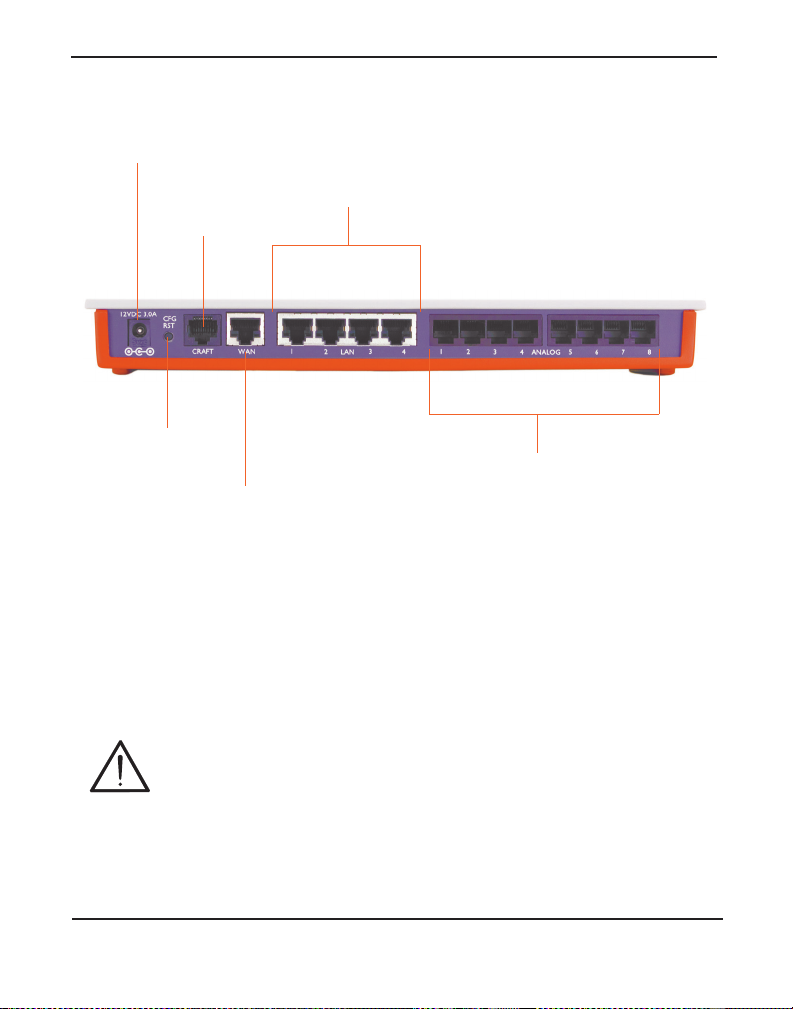
Chapter 2: Unit Installation
Configuration
Reset Sw itch
Craft
Port
WAN
Port
Power
Supply
Analog
Ports
LAN
Ports
Installin g the A st eris k Appliance 50
1. Remove the Compact Flash cover plate and insert the Compact Flash
Figure 3: Asterisk Appliance 50 Back View
card before connecting the power supply.
Caution.
The Compact Flash is not hot swappable. The Compact Flash
card sh ould be inserted before powering on the unit. Likewise,
before removing the Compact Flash card it should be
unmounted (using the unmount command) and the Asteri s k
Appliance 50 should be powered off.
Digium, Inc. Page 24
Page 25

Chapter 2: Unit Installation
2. Connect one end of an Ethernet cable to an Asterisk Appliance 50
LAN port, and one end to an Ethernet connection on a computer
configured to obtain an IP address automatically (DHCP). This step
will connect your Aster isk Appliance 50 to your computer so that you
may access the Asterisk Appliance 50 GUI from your computer.
3. Connect the provided power cable to the power supply. You can then
connect the power supply to the Asterisk Appliance 50’s DC power
connector . The Ast eris k Appl iance 50 will immedia tely power on once
connected to a power source.
4. Using an Asterisk Appliance 50 supporte d web browser, open a
browser window and enter the IP address for the Asterisk Appliance
50. The default LAN I P address i s 192 .168.69. 1. The def ault use rname
is admin, and the default password is password.
Note: The first time you log on you will be prompted to change
your password from the default. You will then be prompted to log
on with the ne w password. Once th e log on process is complete the
AsteriskGUI home page will be displaye d.
5. You may find it preferable t o enable the Aster isk App liance 5 0 GUI on
the WAN interface for ease of use. Once you have logged on to the
Asterisk Appliance 50, click on the Networking menu, and then the
WAN tab.
6. Select the Enable GUI on WAN interface checkbox.
7. Click Save, and then click Apply Changes. Your changes will be
applied and Asterisk will reload.
8. Attach the eth ernet cabl e co nn ect ed to t he Asteri sk App lia nce 5 0 ’s
LAN port to the WAN port. Connect the other end of the cable to the
appropriate inte rnet connection (will vary depending on your setup).
This will connect the Asteri sk Appliance 50 to the internet.
Digium, Inc. Page 25
Page 26

Chapter 2: Unit Installation
9. Connect telephones to the analog por ts tha t are configured as FXS
ports and conne ct phon e line s to th e analog por ts that ar e confi gured as
FXO ports.
10.Using an Asterisk Appliance 50 supported web browser, open a
browser window and enter the IP address for the Asterisk Appliance
50. The default username is admin, and the password is will be the
password you chose after firs t logging into the Asterisk Appliance 50.
11. You are now ready to configure your Asterisk Applianc e 50 via the
GUI.
Caution.
This unit must be connected to the Teleco mmu nications
Network in your country using an approved line cord, e.g.: for
Australia use only line cords complying with ACA Technical
Standard TS008.
Digium, Inc. Page 26
Page 27

Chapter 2: Unit Installation
Mounting the Asterisk Appliance 50
Figure 4 below illustrates the proper mounting installation options:
Figure 4: Mounting Instructions
Warning.
Do not place anythi ng (including paper) on top of th e Asterisk
Appliance 50. To allow proper cooling, these units must not be
stacked.
Digium, Inc. Page 27
Page 28

Chapter 2: Unit Installation
Table 2: W a ll Moun ting
Step Instru c tio n s for Wall Mounting
1 Select the area to mount the Asterisk Appliance 50 unit
(ref er to Figure 4 on page 27). The unit should be
mounted at or below eye level to properly view the
LEDs.
2 Install two #8 PAN headscrews (1 1/2-inc h or long er)
into the desired location on the wall . They should be
placed approximately 7 1/2-inc he s, or 19cm, apar t
horizontally or vertically, which is the distance between
the two keyed insets on the back of the Asterisk
Appliance 50. Make sure that the two screws are in
alignment and level.
3 Leave approximately 1/4-inch of the screw protruding
from the wall to allow th e head of the scr ews to slide i nto
the keyed insets, mounting the unit to the wall.
Warning
The Asterisk Appliance 50 should not be mounted with the
LEDs pointing downward. Mounting the Asterisk Appliance 50
with the LEDs point ing downward ma y cause a disruption in
air circulation, which could cause the Asterisk Appliance 50 to
overheat. Mo unting t he As teri sk Appl ianc e 50 th is way ca n also
expose the LAN, WAN, and analog ports to potential damage.
Digium, Inc. Page 28
Page 29

Chapter 3 Telephone System Configuration
This chapter provides infor mation on how to initially set up your
telephone system via the AsteriskGUI™. The following topics are
covered:
Log On to the Asterisk Appliance 50 on page 31
The Asteris k Appliance 50 Inte rface on page 32
Analog Hardware Configuration on page 35
Trunk C onfiguration on page 40
Outgoing Calling Rules on page 55
Dial Plans on page 59
User Extens i ons on page 61
Ring Groups on page 68
Music on Hold on page 70
Call Queu es on page 72
Agent Login Settings on page 77
Voice Menus on page 78
Record a Voice Menu on page 85
Time Intervals on page 87
Incoming Calling Rules on page 89
Voicemail on page 93
Paging/Intercom on page 97
Conferencing on page 101
Follow Me on page 104
Digiu m, In c . Page 29
Page 30

Chapter 3: Telephone System Configuration
Directory on page 110
Call Features on page 112
Voic e m a il Groups on page 122
System Info on page 123
Networking on page 124
G.729 Codec on page 127
Backup on page 130
Update on page 131
Options on page 134
The Asterisk Appliance 50 comes with Embedded Asterisk Business
Edition™. The software includes the AsteriskGUI, a web based
configuration int erface. The AsteriskGUI gives you the ability to set up
your telephone system withou t the need to use command line
configuration. Aft er connecti ng to the Asterisk Appli ance 50, the primary
menu is displayed, giving you the ability to configure your system, as
well as add features to your call system as your needs change.
Digium, Inc. Page 30
Page 31

Chapter 3: Telephone System Configuration
Log On to the Asterisk Appliance 50
Your Asterisk Appliance 50 should alr eady be connected to an int ernet or
network connection, as described in Installing the Asterisk Appliance
50 on page 24. In the address field of an Asterisk Appli ance 50 supported
web browser , e nter t he IP addre ss assi gned to your Aste risk Appli ance 50.
The default LAN IP address is 192.168.69.1.
Figure 5: GUI Login
T o log on to the system enter the following credenti als:
Username: admin
Password: <password>
The first time you log on you will be prompted to change your password
from the default. You should have already chosen a new password during
the installation pr ocess. Once the log on process is complete the
AsteriskGUI home page will be displaye d.
Digium, Inc. Page 31
Page 32

Chapter 3: Telephone System Configuration
The Asteris k Appliance 50 Inte rface
The AsteriskGUI gives you the ability to configure the basic hardware
and dial plan elements you need when initially setting up your system.
You must create trunks, system users, conferencing, voice mail, etc. After
logging into the AsteriskGUI , you’ re presented with a variety of options
on the left side of the page.
Figure 6: System Status Page
Digium, Inc. Page 32
Page 33

Chapter 3: Telephone System Configuration
The AsteriskGUI supports the following browsers:
Firefox 1.5 through 3.0
IE 7
Safari 3.x
Opera 9.x
Every page of the GUI has two columns. The le ft co lumn identif ies a ll the
elements for which you can program the Asteri sk Applia nce 50. The
elements listed b egin w i th Sys tem Status, which is the first page you see
upon logon, and proc eed down to Options. Clicking any of the tabs on the
left of the page opens the correspo nding pa ge in the right column. Many
pages have additional information. Click on the information symbol, a
blue “i” enclosed in a circl e, to get more informati on about a field or page.
The System Status page is the default page. This page shows you the
current version of firmwar e you are using, the status of any trunk lines
you have configured, the realtime status and additional details of all user
extensions, including the new and old voicemail message count for each
user extension (e.g. Messages: new/old), and the realtime status of all
agents, conference rooms, and parked calls. You can click on most
extension definit ions to get more information. In addition, the System
Status page gives you the ability to log in, log out, pause, and unpause an
agent that is associated with one or more call queues.
Note: A user extens ion will have the status of “Unavaila ble” when the
VoIP account associated with it is not registered to the Asterisk
Appliance 50. The s ta tus will n ot c hange to “Unava ilable” when a use r
extension has both an analog port and a VoIP account associated with
it.
In the upper right corner of each page you will see the Apply Changes
and Logout buttons. Click Apply Changes to save and activate any
Digium, Inc. Page 33
Page 34

Chapter 3: Telephone System Configuration
changes you have made on a page so that you can utilize the changes.
Click Logout on any page to exit the Asterisk Appliance 50 GUI.
Digium, Inc. Page 34
Page 35

Chapter 3: Telephone System Configuration
Analog Hardware Configuration
You must configure your analog hardware according to the needs of your
system as part of your initial Asterisk Appliance 50 configuration. The
Configu re Hardw a re page gives you the ability to configure both your
FXS and FXO ports, as well as your Tone Region, operation mode,
message waiting indicator mode (MWI), e tc . The number of FXS and
FXO ports available for configuration will depend on the Asterisk
Appliance 50 model you purchased. Click the C onfigure Hardware tab
to configure your analog hardware.
Note: The Configure Hardware tab will not be available if you
ordered a VoIP only model.
Figure 7: Configure Hardware
Digium, Inc. Page 35
Page 36

Chapter 3: Telephone System Configuration
FXS and FXO ports provide the ability to receive and send calls through
the traditional telephone network, or POTS (Plain Old Telephone
System). FXS modules provide both dial tone and ringing voltage to an
analog phone. FXO modules accept dial tone and provide an interface to
the traditional phone lines. You plug a telephone line into an FXO port,
and an analog telphone into an FXS port.
On this page you can specify the signalling type for your FXS and FXO
ports. You have two choices; either Kewl Start or Loop Start. The Loop
Start method use s a short to r eques t a dial tone . All Nort h American home
phone lines use loop sta rt si gnalling. Kewl S tart is t he s ame as Loop S tart ,
but is better able to detect dis connects. Select either Kewl Start or Loop
Start for each FXS and FXO module. Kewl Start is the default and is
preferred for analog circuits in Asterisk.
Note: Ground Start signalling is not supported.
You also need to select a tone region, which defines the set of tones (dial
tones, ringing tone, busy tone, etc) used in your region. Select your
country, or the nearest neighboring country, from the Tone Region drop-
down list. The default setting is North America (United States/Canada).
Digium, Inc. Page 36
Page 37

Chapter 3: Telephone System Configuration
Advanced Analog Options
There are also some advanced settings which are applied to your analog
hardware. Specify them as needed, or accept the default values.
Opermode - Setting operation mode, or Opermode, sets the On Hook
Speed, Ringer Impedance, Ring er Threshold, Current limiting, T ip/
Ring voltage adjustment , Minimum Operational Loop curre nt, and and
AC Impedance selection as predefined for each countries analog line
characteristic s. Select the country in which your Asterisk Applianc e
50 is operating.
A-law Override - Set th e audio compression scheme. The setting you
choose is dependent on the country of operation. Ulaw is used in the
United States and Canada. A-law is used in most other countries. If
possible confirm the scheme which will be best for operation of your
Asterisk Appli ance 50.
FXS Hono r M ode - This setting lets you choose whether you apply
the opermode setting to your FXO modules only, or to both FXS and
FXO modules.
Boostringer - Set the voltage used for ringing an analog phone. Nor-
mal will set ring volt age to a normal le vel, or Peak will set the volt age
to 89v .
Fast Ringer - The fast ringer tone can be set to normal, or to a 25hz
tone.
Lowpower - The low power setting can be set to normal, or to a Fast
Ringer peak of 50v.
Ring Detect - Users who are experien cin g trouble detecting Caller ID
from Analog service provide rs or whose lines exhibit a polarity rever sal before Calle r ID is tr ansmitted fr om the p rovider s hould sele ct Full
Wave. Otherwise, choose Standard.
Digium, Inc. Page 37
Page 38

Chapter 3: Telephone System Configuration
MWI Mode - This option allows the user to specify the type of Mes-
sage W a iti ng Indica tor det ection to be done on tr unk (FXO) i nterfac es.
The option s are none, which performs no detecti on, FSK which performs Frequency Shift Key detect ion, or NEON which perform Neon
MWI dection. The default value is none.
Echo Cancellation NLP Type - This option allows you to specif y the
type of Non Linear Processor you want appli ed to the post echo- cancelled audio reflections received from analog connections. There are
several options:
– None - This setting disables NLP proces sing and is not a recom-
mended setting. Under most circumstances, choosing None will
cause some residual echo.
– Mute - This setting causes the NLP to mute inbound audio streams
while a user con nect ed to the appliance is speak in g . For use rs in
quiet environments, Mute may be acceptable.
– Random Noise - This sett ing ca uses t he NLP to i nject r andom no ise
to mask the echo reflecti on. For users in normal env ironments, Ran-
dom Noise may be acceptable.
– Hoth N oi se - This setting c auses the NLP to in ject a low-end Gauss-
ian noise with a frequency spectrum similar to voice. For users in
normal environments, Hoth Noise may be acceptable.
– Suppressio n N LP - This setting causes the NLP to suppress echo
reflections by reducing the amplitude of their volume. Suppression
may be used in combination with the Echo cancellation NLP Max
Digium, Inc. Page 38
Page 39

Chapter 3: Telephone System Configuration
Suppression option. For users in loud environments, Suppression
NLP may be the best option. This is the default setting for the Echo
Cancellation NLP Type option.
Echo Cancellation NLP Threshold - This option al lows you to spec-
ify the threshold, in dB difference between the received audio (post
echo cancellation) and the transm itted audio, for when the NLP will
engage. The default setting is 24 dB.
Echo Cancellation NLP Max Suppression - This option, only func-
tional when the Echo Cancellation N LP Type option is set to Sup-
pression NLP, specifies the maximum amount of dB that the NLP
should attenu ate the residual echo. Lower numbers mean that the NLP
will provide less suppression (the residual echo will sound louder).
Higher numbers, especially those approaching or equaling the Echo
Cancellation NLP Threshold option, will nearly mute the residual
echo. The default setting is 24 dB.
Note: The VPM Settings section will not be visible on older ha rdware
revisions of the Asterisk Appliance 50.
Once you have made the configuration changes to your hardware which
you require, click Save Changes. A message will display letting you
know that in order for these changes to be completed, you must reboot
your Asterisk Appliance 50. Click Options on the left menu, sel ect the
Reboot tab, and then click Reboot Now to reboot your appliance.
Rebooting your Asterisk Applia nce 50 will terminate any active calls.
Digium, Inc. Page 39
Page 40

Chapter 3: Telephone System Configuration
Trunk C onfiguration
Now that you have c onfigured your analog har dware (assuming your unit
had any) you are ready to set up your trunk lines. T runks are outbound
lines used to make calls. Trunks can be either analog or VoIP. Click
Trunks from the main menu to access the trunk configuration page.
Figure 8: Trunk Configuration Page
Trunk de finit ions are used i n c alling rules, dial pl ans , and call r outin g, et c.
You can use a mixture of both analog and VoIP trunks.
Digium, Inc. Page 40
Page 41

Chapter 3: Telephone System Configuration
Analog Trunks
Select the Analog Trunks tab to access the Manage Analog Trunks
page. Here you can create an analog trunk definition for each analog port
on your Asterisk Appliance 50. Click New Analog Trunk to open the
New Analog Trunk definition page.
Figure 9: New Analog Trunk Definition
Digium, Inc. Page 41
Page 42

Chapter 3: Telephone System Configuration
Use the following field definitions as a guide in creating your new analog
trunk definition.
Channels - Select one or more analog channel (port) to be associated
with this trunk.
Trunk N ame - Specify a unique name to help you identify this trunk
when it is referred to in other areas such as calling rules.
Busy Detection - This setting is used to detect far end hangup or for
detecting busy signal . Sele ct Yes to enable this feature.
Busy Count - If Busy Detection is enabled it is also possible to spec-
ify how many busy tones to wait for be fore hanging up. The default is
4, but better results may be achieved by setting to 6 or 8. The higher
the number , the longer it will take to hangup a channel. A higher number also lowers the possibility of false detections.
Busy Pattern - If Busy Detection is enabled, it is also possible to
specify the cadence of your busy signal. In many countries it is 500
milliseconds on, 500 milli secon ds of f. Without Busy Pattern specified,
the Asterisk Appliance 50 will accept a ny regular sound-silence pattern that repeats multiple times as a busy signal. If you specify Busy
Pattern, then the Asterisk Appliance 50 will check the length of the
sound (tone) and silence, which will further reduce the chance of a
false positive.
Ring Timeout - T runk (FXO) devices must have a timeout to deter-
mine if there was a hangup before the line was answered. This value
can be configured to shorten how long it takes before the Asterisk
Appliance 50 considers a non-ringing line to have hung up.
Answer on Polarity Switch - If this option is enabled the recept ion of
a polarity reversal will mark when an outgoing call is answered by the
remote party.
Digium, Inc. Page 42
Page 43

Chapter 3: Telephone System Configuration
Hangu p on Po la ri t y Swi tc h - In some countries, a polari t y reversal is
used to signal the disconnect (or hang up) on a phone line . If the
Hangup on Polarity Switch option is ena bled, the call will be considered “hung up” on a polarity reversal.
Call Progress - On trunk interfaces it c an be useful to follow the prog-
ress of a call throug h Ringing, Busy, and Answering. If turned on, Call
Progress attempts to determine answer, busy, and ringing on phone
lines. This feature is highly experimental and can easily detect false
answers and hang- ups. This may cause a hang up during the middle of
a call. Few zones are supported, but can be selected with the Progress
Zone option.
Progress Zo ne - This option defines the call progress zone for the
trunk interfaces.
Use CallerID - If this option is enabled Caller ID detection is also
enabled.
Caller ID St art - This option allows one to define the start of a caller
ID signal. Select Ring from the drop-down list to start caller ID when
a ring is received , or Polarity, to start caller ID when a polarity reversal is detected.
Caller ID - This opt ion allows the lines to report the c aller ID st ri ng as
received from the telco, or as a fixed val ue by using the adv anced
option.
Pulse Dial - If this option is e nabled, pulse dialing, instead of DTMF,
will be used.
CID Signalling - This opt ion d efines the typ e of caller I D signalli ng t o
use.
– bell - Bell202 as used in the United States
Digium, Inc. Page 43
Page 44

Chapter 3: Telephone System Configuration
– v23 - Used in the UK
– v23_jp - Used in Japan
– dtmf - Used in Denmark, Sweden, and Holland
Mailbox - This setting allows any messag e waiting indicator received
across the asso ciat ed tr u nk to be fo rw ar de d to a local Use r, such as a
SIP phone.
Flas h Timing - Flash Timing defines the duration, in milliseconds,
that Asterisk will use if it is sen ding a flash signal to another system.
Receive Flash T iming - Rec eive Flash T im ing define s t he durati on, in
milliseconds, that Asterisk requires in order to consider a flash ope ration it receives to be valid.
Once you have completed the Analog T runk definition, click Add. A
message will display letting you know that in order for these changes to
be completed, you must reboot your Asterisk Appliance 50. Before doing
so, you may wish to click the Edit button asso ciated with an analog trunk
to configure additional options for tuning the audio.
Digium, Inc. Page 44
Page 45

Chapter 3: Telephone System Configuration
Figure 10: Edit Analog Trunk Definition
The Audio Tuning section will allow you to calibrate your analog ports
for optimum performance. Pleas e ensure that your analog lines are
Digium, Inc. Page 45
Page 46

Chapter 3: Telephone System Configuration
plugged in before clicking the Easy Calibrate button. Your Asterisk
Appliance 50 must not have any active calls in order for the calibration
process to complete successfully on all analog ports. If you wish to reset
the calibration, click the Reset Calibration button.
Note: The Easy Calibration feature can take approximate ly 90 seconds
per port to complete.
In addition, an option to configure the gain level for each port will be
listed. This option can be used to raise or lower the audio level on your
ports. Normally, you should not have to adjust your analog ports beyond
the initial calibration. Should you still need to fine tune your audio
settings, please select one of the following:
Low
Soft
Normal
Loud
Louder
Once you have completed the Analog T runk definition, click Update. I n
order for these changes to be complet ed, you must reboot your Asterisk
Appliance 50. Click Options on the left menu, select the Reboot ta b, and
then click Reboot Now to reboot your appliance. Rebooting your
Asterisk Appliance 50 will te rminate any active calls.
Digium, Inc. Page 46
Page 47

Chapter 3: Telephone System Configuration
Adding Service Providers
You must configure a VoIP service provider in order to connect to the
Public Switched Telephone Network (PSTN) via a VoIP connection.
Access to the PSTN gives you the ability to place calls to telephone
numbers no matter how they connect to the PSTN (VoIP or standard
analog system). Click the Service Providers tab to add a VoIP (SIP or
IAX) service provider.
Figure 11: Add New Service Provider
The list of VoIP service providers and corresponding configuration
information is pulled dyna mically from a secure Digium webservice. If
you are already a VoIP provider customer, select the provider from the
list, click Add, and input your user name and password. Once you have
added a servic e provider it wil l appear in the Ser vice Providers list. There
are Edit and Delete buttons assoc iate d with each Servic e Provider listi ng.
Click Edit to further refine your service provider defi nition. A detailed
definition will be displa yed.
Digium, Inc. Page 47
Page 48

Chapter 3: Telephone System Configuration
Figure 12: Edit VoIP Service Provider
The Edit Service Prov ider page gives you the ability to change your
caller ID, as well as select a range of codecs.
Username/Password - You will need to provide your log on crede n-
tials in order to update your service provider information.
Caller ID - The caller ID sent to the PSTN will be set to the value
specified in this fie ld.
Codecs - Codecs pr ovide the a bility f or you r voic e to b e conv erted t o a
digital signal and transm itted across the Internet. The quality of your
call can be affect ed by the choice you make. The codecs available to
you will depend on what is supported by the service provider you
choose. You can select the order in which the codecs are used. The
codecs commonly avail able are u-law, a-law, GSM, G.726, G.722, and
G.729A. A registered G.729A license is required in order to use the
G.729A codec.
Digium, Inc. Page 48
Page 49

Chapter 3: Telephone System Configuration
Click Update when you have completed your changes, or Can cel to
discard your changes.
Digium, Inc. Page 49
Page 50

Chapter 3: Telephone System Configuration
Adding VoIP Trunks
If you do not have a subscription with one of the VoIP providers listed
above, or you have a special VoIP setup, you can add a custom VoIP
trunk. Click the VoIP Trunks tab to add a VoIP (SIP or IAX) service
provider. The Create New SIP/IAX Trunk page will be displ ayed.
Figure 13: Create New SIP/IAX Trunk Definition
Fill in the i nitial SIP/IAX trunk definition with the following information:
Type - Select either the SIP or IAX protocol.
– SIP - Identifies that the trunk sends and receives calls using the
VoIP protocol SIP.
Digium, Inc. Page 50
Page 51

Chapter 3: Telephone System Configuration
– IAX - Identifies that the turnk sends and rec eives calls using the
VoIP protocol IAX.
Provider Name - Enter a unique name to help you identify this trunk
for use in calling rules, etc.
Host name - The hostna me or IP address assigne d to t he VoIP provider
or server.
Usernam e/P a sswo r d - You will need to provide your log on creden-
tials to the VoIP trunk server.
Note: If your VoIP trunk does not require a username, you may leave
the username field blank.
Click Add once you have completed your defini tion, or Cancel to discard
your changes.
Once you have added a VoIP trunk it will appear in the SIP/IAX trunks
list. There are Edit and Delete buttons associated with each VoIP trunk
listing. Click Edit to further refine your trunk definition.
Digium, Inc. Page 51
Page 52

Chapter 3: Telephone System Configuration
Figure 14: Edit VoIP Trunk
The following options will be available:
Provider Name - Enter a unique name to help you identify this trunk
for use in calling rules, etc.
Host name - The hostna me or IP address assigne d to t he VoIP provider
or server.
Username/Password - You will need to provide your log on crede n-
tials in order to update your service provider information.
Codecs - Codecs pr ovide the a bility f or you r voic e to b e conv erted t o a
digital signal and transm itted across the Internet. The quality of your
call can be affect ed by the choice you make. The codecs available to
you will depend on what is supported by the service provider you
Digium, Inc. Page 52
Page 53

Chapter 3: Telephone System Configuration
choose. You can select the order in which the codecs are used. The
codecs commonly avail able are u-law, a-law, GSM, G.726, G.722, and
G.729A. A registered G.729A license is required in order to use the
G.729A codec.
Caller ID - This is the number the trunk will try to use when making
outbound calls. For some providers it is not possible to set the CallerID with this option. Thus this option may be ignored. When making
outbound calls the follo wing rules are used to determine which Caller
ID is used, if they exist:
– The first Caller ID used is the Global CID defined in the Options
tab.
– The Caller ID set in the VoIP Trunks configuration, if defined,
takes precedence over the Global CID.
– The Caller ID set for the user making the call as defined in the
Users page will take precedence over the Global CID and the CID
set in VoIP trunks.
From Domain - If requir ed by your provider, specify your primary
domain identity to show in the domain fiel d of the From header for
outgoing SIP invites. Otherwise, only your IP address will be sent in
the From header.
From User - If required by your provid er, specify the user to show in
the user field of the From header for outgoing SIP invites. Otherwise,
only your IP address will be sent in the From header.
Insecure - This is a SIP parameter used to determine peer matching.
The setting determines whet her or not an insecure connection will be
allowed, or if authentication is required. The valid options are:
– port - Enter this value to match against only an IP address. This set-
ting is useful if you have multiple endpoints behind a NAT device.
Digium, Inc. Page 53
Page 54

Chapter 3: Telephone System Configuration
– very - Specify this valu e if you do not want t o re quire a uthentic ation
upon an initial invite.
– no - Specify this value if you do not want to allow an insecure con-
nection.
Enable Remote MWI - When you select this option, you enable
voicemail from your remote provider. Typical ly a user’s voicemail is
stored locally on the Asterisk Appliance 50. The notification of new
voice mail is provided by the same lo cal Asterisk Appli ance 50. I f you
would like to receive voicemail notifications from a remote provider,
this option i s available. To enable this option, clic k the check box, and
in the Remote Mail Box field, specify the remote mail box number or
identity to whi ch you wi sh t o sub scrib e, e.g. 6001. Sele ct th e loc al use r
who should receive this MWI notification. Please note: enabling this
option for a local user will disable the local user’s Asterisk Appliance
50 voice mai l. It is not possible to provide local voice mail and remote
MWI simu ltaneously.
Click Add when you have completed your changes, or Cancel to discard
your changes.
Digium, Inc. Page 54
Page 55

Chapter 3: Telephone System Configuration
Outgoing Calling Rules
An outgoing calling rule pair s an exten sion pattern with a trunk used to
dial the pattern. This allows different patterns to be dialed through
different tr unks (e.g. "local" 7-digit dials through an analog line but "long
distance" 10- digit dials through a low-cost SIP trunk). You can optionally
set a failover trunk to use when the primary trunk fails. The Outgoing
Calling Rules give you the ability to use basic pattern matching to
differentiate outbound calls and route them accordingly. The tab displays
each outgoing calling rule established and the service providers assigned.
Figure 15: Outbound Calling Rules
Note: Outbound Calling Rules m anages onl y indiv idual outg oing
call rules. See the Dial Plans section to a ssocia te multipl e outgoing
calling rules to be used for User outbound dialing.
The Calling Rules menu shows every rule name established, the pattern
the rule will match against, the trunk used to complete the call, and the
failover trunk to be used. of call. Several default calling rules will be
available when you initia lly set up your Asterisk Appliance 50. Click on
Digium, Inc. Page 55
Page 56

Chapter 3: Telephone System Configuration
Add a Calling Rule to define a new calling rule. The following dialog
will be disp layed .
Figure 16: New Calling Rule
A calling rule is comprised of the following items:
Calling Rule Name - Choose a name that describes the type of rule
you are creating, e.g. “Local” or “Long Distance”.
Pattern - The Pattern field gives you the ability to use basic pattern
matching to differentiate calls and route them accordingly. For
instance, if a number begins with _9256, a nd is followed by 7 or more
digits, that would define a call within the state of Alabama. If a call
began with _9 followed by 7 digits, it would be a local call that proba-
Digium, Inc. Page 56
Page 57

Chapter 3: Telephone System Configuration
bly doesn’t require a long distance charge. Instead of adding a rule for
every extension or phone number you call, spe cify the pattern in this
rule similar to the example. All patterns begin with the unders core “_”
character. There are special characters which can be used in patterns:
– X - Any digit from 0-9
– Z - Any digit from 1-9
– N - Any digit from 2-9
– [1,2,3,6-9] - Any di git within the br ackets, in this instance 1, 2 , 3, 6,
7, 8, 9.
– . - The period is the wildcard which will match anyth ing remaining.
For example, _9011. matches anything starting with 9011.
– ! - The exclamation point is a wildcard which causes the matching
process to complete as soon as it can determine that no other
matches are possible.
Send to Local Destination - Calls matching the pattern specified will
be routed to the destinatio n specif ied in Destination if this checkbox
is selected.
Destination - Specify a destination, such as voicemail or main menu,
for calls to be routed to when the Send to Local Destination check-
box is selected.
Use Trunk - Specify the trunk through whic h calls, matching the spec-
ified pattern, will be placed.
Strip - This option gives you t he a bility t o r emove spec ified num ber of
digits from the front of the call string before the call is dialed and
placed thro ugh the trunk specified in Use Trunk.
Digium, Inc. Page 57
Page 58

Chapter 3: Telephone System Configuration
Prepend Thes e Digi ts - This option gives you the opportunity to add
digits to the front of the call str ing before the call is dialed and placed
through the fail over trunk. For example, a 3 digit area code could be
prepended to a 7 digit string for calls to a service provider which
requires 10 digit dialing.
Note: You may also prepend the ‘w’ character for analog trunks to
provide a 500ms delay before dialing. This is useful if your
telecommunications provider does not immediately provide dial tone
after going off hook.
Use Failover Trunk - Failover trunks can be use d to ensure that a call
goes through i f the primary trunk is busy or down. If the Use Failover
Trunk checkbox is selected and Fail Over Trunk is specified, then
calls that can not be placed through the primary trunk will be placed
through this alternate route. If your primary trunk is a VoIP trunk, but
you want calls to be placed through the PSTN when the VoIP trunk
isn’t availa ble, then this option will suit your needs.
Once you have completed the calling rul e defi nition click Save to accept
the rule or Cancel to abandon your changes. Click Apply Changes in the
upper right corner of the page to make your changes immediately
available. Click Edit next to a rule on the calling rule list to edit a
previously defined ru le, or Delete to delete the rule.
Digium, Inc. Page 58
Page 59

Chapter 3: Telephone System Configuration
Dial Plans
A Dial Plan is a collection of Outgoing Calling Rules. Dial Plans are
assigned to user extensi ons to specif y the dialing permissions associated
with that extension. For example, you might have one Dial Plan for local
calling that only permit s extensions associated with that Dial Plan to dial
local numbers, via the "local" outgoing calling rule. Another extension
may be permitted to dia l long dista nce numbers, and so wou ld have a Dia l
Plan that includes both the "local" and "longdistance" outgoing calling
rules.
Click New at the top of the Calling Rules page and c rea te a new dial plan
name. You can then add calling rules for that dial plan definition.
Figure 1 7: Cr eate New Di al Pl an
The default dial plan, the colle ction of your calling rules, is
Default_Dialplan. You can create more than one dial plan, especially if
you want to have di ff erent dial pl an s for different user e xtensio ns. Change
the DialPlanName, and then select the checkbox fo r eac h Outgoing
Calling Rule associated with this plan. You can also select which local
contexts, such as conferences, voicemenu, and queues should be part of
the dial plan.
Once you have completed the dial plan definition clic k Save to accept the
plan, or Cancel to abandon your changes. Click Apply Changes in the
Digium, Inc. Page 59
Page 60

Chapter 3: Telephone System Configuration
upper right corner of the page to make your changes immediately
available. Click Edit next to a dial plan on the list li st to edit a previously
defined plan, or Delete to delete a dial plan.
Digium, Inc. Page 60
Page 61

Chapter 3: Telephone System Configuration
User Extens i ons
The User Extensions page is used to create individual user accounts on
the system. Each user definition includes an extension, name, password,
etc. User extension definitions are the basic components of your phone
system. They are n eede d for v oic email, conferenc ing , call que u es, dia l
plans, etc. Click the Users tab to view the main User Extensions page.
Figure 18: User Extensions
The main pag e lists al l previ o us ly crea t ed user ex t ens i ons. You can edit
individual users as well as cha nge attr ibutes of several users at the same
time. Your first step when setting up a new system will be to create one or
more users. Click Create New User to create a new user extension.
Digium, Inc. Page 61
Page 62

Chapter 3: Telephone System Configuration
Figure 19: Create New User
Extension - The numbered extension, e.g. 6000, assigned to the
defined user. The extension must be a number within the range specified in Extension Preferences on the Options page.
Name - The first and last name of the indivi dua l assigned to this
extension. The name can also be that of a department, such as Sales or
Support, for example. This is important because the Dial By Name
Directory function of Asterisk uses this information to route calls.
Digium, Inc. Page 62
Page 63

Chapter 3: Telephone System Configuration
Dial Plan - This option references the Dial Plans option on the left
tool bar. Based on the calling rul es you’ve created, you can restrict the
outbound dialing of this exte nsion to local calls, emergency calls, and
standard long-dis tance calls for North America. This opti on also possibly allows blocking or allowing international (011 prefix dialed) calls.
Caller ID - Iden tifies the Ca ller ID presented when the listed exten-
sion dials an internal extension.
Outbound Caller ID - Identifies the Caller ID presented when the
listed extension dia ls an extenal number. Your ability to manipulate
your outbound CID may be limited by your VoIP provider. Manipulation of CID across analog trunks is not possible.
Enable Voicemail - Builds a voice mail box for the extension that can
be reached by dialing the Check Voicemail extension. The Voicemail
extension can be configured. The current default is 6050.
V oice Mail Access Pin Code - The password used to access voicemai l
for the specified ext ens ion .
E-mail Address - Voice mails received by this extension can be sent
as audio file attachments e-mailed to a specific address.
SIP - Identifies wh et her the ex ten s ion s en ds and rece ive s ca lls usin g
the VoIP protocol SIP.
IAX - Identifies whether the extension sends and receives calls using
the VoIP protocol IAX.
Analog Station - A drop-down menu is available to identify the ana-
log phone port which this extension will access. If more than one
phone is connected to your Asteris k Appliance 50 you may need to
confirm the port number liste d on the back of the Aster isk Appliance
50.
Flash - Flash Timing defines the duration, in milliseconds, that Aster-
isk will use if it is sending a flash signal to a nother system.
Digium, Inc. Page 63
Page 64

Chapter 3: Telephone System Configuration
RXFlash - Receive Flash Time defines the duration, in milliseconds,
that Asterisk requir es in order to consider a flash operation that it
receives to be valid.
Codec Preference - Codecs provide the ability for your voice to be
converted to a digital signal and transmitted across the Internet. The
quality of your call can be affected by the choice you make. The
codecs available to you will depend on what is supported by the service provider you c hoose. You can select the order in which t he codec s
are used. The codecs commonly available are u-law, a-law, GSM,
G.726, G.722, and G.729A. A registered G.729A license is required in
order to use the G.729A codec.
MAC Address - The MAC Address field is used to specify the MAC
address of a P olyCom
® phone connect ed to t he Aste risk Applianc e 50.
The MAC address associates the phone with thi s extension and
enables the auto-synchr oniz ation of provisioning information.
Line Number - Polycom brand VoIP phones are capable of servicing
1 to 6 separate VoIP phone lines, depending on the model of the
phone. If you are using the Polycom Auto-provisioning feature of the
Asterisk Appliance 50, this option can be used to define which line of
your phone will be used by the user. No more than one user can be
assigned to a line on a phone.
Note: Each phone must be configured with a user that has Line
Number set to 1. Additionally, assigned line numbers must be in a
contiguous range.
Line Keys - Polycom brand VoIP phones include multiple line keys.
The number of line keys available will depend on the model of the
phone. If you are using the Polycom Auto-provisioning feature of the
Asterisk Appliance 50, this option can be used to define how many
line keys on the phone should be associat ed with this user (e.g. Let’s
Digium, Inc. Page 64
Page 65

Chapter 3: Telephone System Configuration
says you configur e a single Polycom phone with two users. User 6000
with Line Number set t o 1 and Line Key se t to 2 will disp lay use r 6000
on line keys 1 and 2 on the phone. User 6001 with the same MAC,
Line Number set to 2, and Line Key set to 4 will display user 6001 on
line keys 3, 4, 5 and 6 on the phone.). Be sure not to select more line
keys than your phone supports.
SIP/IAX Password - The password used if the user has a SIP/IAX
account.
NAT - Tr y this setting when your Asterisk Appliance 50 is on a public
IP, communicating with devices behind a NAT device (broadband
router). If you have one-way audio prob lems, you usually have problems with your NAT configuration or your firewall's confi guration of
SIP and RTP ports.
Can Reinvite - By default, the Asterisk Appliance 50 will route the
media streams from SIP en dpoints through itself. Enabling this option
causes the Ast erisk Appliance 50 to a ttempt to negotiate the endpoints
to route the media stream directly. It is not always possible for the
Asterisk Appliance 50 to negotiate endpoint-to-endpoint media routing. This option can be used to tell the Asterisk Appliance 50 whether
or not to issue a reinvite to the client.
DTMF Mod e - Set t he default DTMF mode for sendin g DTMF (touch
tone). The default setting is rfc2833. Other options include:
– info - Used to display SIP Info messages
– inband - Inband audio (requires 64 kbit codec - alaw, ulaw)
– auto - Use rfc2833 if offered, inband otherwise.
Insecure - Insecu re is a SIP paramet er used to determine peer match-
ing. The setting determine s whether or not an insec ure conne ction will
be allowed, or if authentication is required. The valid options are:
Digium, Inc. Page 65
Page 66

Chapter 3: Telephone System Configuration
– port - Enter this value to match against only an IP address. This set-
ting is useful if you have multiple endpoints behind a NAT device.
– invite - Enter this value to match against both the IP address and
port number provided in the Contact field of the SIP header. A call
will be allowed without authentication if a match is found.
– very - Specify this valu e if you do not want t o re quire a uthentic ation
upon an initial invite.
– no - Specify this value if you do not want to allow an insecure con-
nection.
3-Way Calling - Allows the extension to receive a call and then dial
out to another phone number to conference with the inbound call and
the recipient of the outbound call.
In Directory - Check this option if you want a user to be searchable
using the system telephone directory.
Call Waiting - I f call waiting is not enabled, the extension accepts
only one call before it is identi fied as busy.
CTI - Selecting this option (Computer Telephony Integration) all ows
the user to connect appli cati o ns to the As te risk Ma na g em en t Interface.
Is Agent - Call queuing is made up of a bank of agents who receive
calls. An extension listed as Is Agent can be added to queues from t he
Call Queues opti on.
Pickup Group - A Pickup Group is a group of user extensions. Each
member of a pickup group can answer another member’s phone by
dialing *8. Select the pickup group to associate with the user extension.
Once you have completed the user extension definition click Save to
accept the defi niti on , or Cancel to abandon your changes. Click Apply
Changes in the upper right corner of the page to make your changes
Digium, Inc. Page 66
Page 67

Chapter 3: Telephone System Configuration
immediately available. Click Edit next to a user extension on the list to
edit a prev iously defined extension, or Delete to delete the user definition.
Editing Multiple User Definitions
You can edit multiple user definitions by selecting one or more user’s
checkboxes and then click Modify Selected Users. You will be able to
edit the definition attributes common to all users such as Dial Plan,
voicemail PIN, or Pickup Group setting. Click Update to update the
selected use rs, o r Cancel to abandon your changes. You can also delete
multiple users by selecting one or more users from the displayed list and
clicking Delete Selected Users. Click OK to complete the deletion, or
Cancel.
Digium, Inc. Page 67
Page 68

Chapter 3: Telephone System Configuration
Ring Groups
Ring groups allow a group of phones, or devices, to ring simultaneously
or in sequence (ring order). This provides the opportunity for multiple
people to answer a call (ri ng all) or one person can a nswer a call from any
phone. The Asterisk Appliance 50 does not come with a default ring
group. To create a new ring group click Ne w Ring Gr oup at the top of the
Ring Groups page.
Figure 20: New Ring Group
Note: You need at least one member to be able to define a ring group.
You will not be able to define a ring gro up without a ny user
extensions.
Digium, Inc. Page 68
Page 69

Chapter 3: Telephone System Configuration
T o create a ring group, use the following procedure.
1. Define the Name of the group. The name can be any mnemonic such
as Sales or Technical Support.
2. Specify an extension to associate with the ring group. This is the
extension that can be dialed to ring all members of the group
simultaneously or in order of listing.
Note: Go to Options, Ge ner a l Preferenc es to see which range of
numbers have been specified for ri ng gro ups.
3. Choose the members of the ring group from the Available Users list.
Click on a user extension or trunk, and then click the arrow pointed at
the Ring Group Members list to transfer. Select a user extension or
trunk in the Ring Group Members list and then click the arrow
pointing toward Available Users to transfer the selected item back to
the list. Click the double arrow symbol to transfer all group members
back to the Available Users list.
4. Choose a ring group strategy from the Strategy drop-down list. You
can choose either Ring All which wil l ring all phones in the defined
group simultaneousl y, or Ring Order which will ring phones in
sequence determined by the order of the users or trunks in the group.
5. Specify the number of seconds that each phone (or all phones) should
ring before ringing the next phone in order.
6. Lastly, determine which action you want the syste m to take if no one
answers the call. You can either direct the call to the voice ma il of a
user , go to an IVR menu, or end the call.
Digium, Inc. Page 69
Page 70

Chapter 3: Telephone System Configuration
Music on Hold
Music on hold is the music played to individuals on hold or during
conference calls while conference members are waiting for the call to
begin. The Asterisk Appliance 50 comes with a default group, or class, of
sound files which can be used for music on hold. Click Music on Hold
and then select the default class to see the list of default sound files.
Figure 21: Music on Hold
If you think the default music is accep table, but you’d like to give your
system a more customized feel, you can also upload your own music or
sound files. Each file uploaded must be less than 10 megabytes, in 8KHz
mono, and in ulaw, alaw, g722, or gsm format. Not sure how to convert
your audio to an a cceptable format? Linux u sers should tr y the Sox util ity,
and Windows users should look into Audacity. Any conversion program
is acceptable as long as the file meets the upload criteria.
Digium, Inc. Page 70
Page 71

Chapter 3: Telephone System Configuration
Click New MOH Class to creat e a new label for a new group of music on
hold files. Select the newly created class from the Music on Hold list, and
then use the upload form to upload new music on hold files to the list.
Once you have uploaded your files, click Apply Changes to make the
files available . You can now use them for call queues, parked calls,
conferences, et c.
Digium, Inc. Page 71
Page 72

Chapter 3: Telephone System Configuration
Call Queu es
A call queue lines up callers and allows them to wait to speak to any
group of empl oyees taking a high volume of cal ls. The feature allows you
to speak to more peopl e rat her t han send call ers back to voice mail to
leave a messa ge and receive a call back wh en time permi t s.
Asterisk identifies which extensions under the Users tab are capable of
belonging to a call qu eue by whether the Is Agent option is selected. The
Is Agent option indicates tha t the user is available to answer customer
calls. If a check mark does not appear next to Is Agent, that extension
won’t appear in the lis t of agent s in the configuration for this option.
Figure 22: New Call Queue
Digium, Inc. Page 72
Page 73

Chapter 3: Telephone System Configuration
The Call Queues page, with the Queues tab select ed, lists the existing
queues. None will be listed if you have not yet created a queue. To create
a new queue, click Create New Queue. Use the following steps to create
a queue. Keep in mind the purpose of the queue and how it should
operate.
Creating a Queue
1. The extension for the queue will automatically populate in the Queue
field with the next available extension. If you want the number to be
something other than the automatically chosen one, enter it in the
Queue field.
Note: Go to Options, Ge ner a l Preferenc es to see which range of
numbers have been specified for ri ng gro ups.
2. Next, give the queue a name that will be meaningful. The queue will
be referenced by this name, so be sure to make it suf ficiently
descriptive as well . For example, “T ech nical Support” for the technical
support que ue, “S al es”, and so o n .
3. You now should choose the strategy used in your queue call logic.
Using the Strategy drop-down list, choose one of the following
options for routing calls:
– Ring All - Rings ever y agent who isn’t on an active c all when a new
call arrives. The first agent to answer the call receives it.
– Round Robin - Every available agent receives a call in turn, akin to
how cards are dealt in a poker game.
– Least Recent - The agent who has been without a call the longest
receives the next call.
Digium, Inc. Page 73
Page 74

Chapter 3: Telephone System Configuration
– Fewest Calls - The a gent who has handled the fewes t calls receives
the next incoming call.
– Random - Goes by the luck of the draw; any agent can receive the
next incoming call.
– RrMemory - This option is Round Robin wit h Memory. It’s similar
to Round Robin, but smarter — it remembers over the course of
days, weeks, or ye ars which agent rec eived the last c all so that it can
commence with the next agent in sequence when calls begin again.
4. The Agents box lists all Users that are designated as an agent that c an
receive calls as part of a call queue. All use rs listed have the Is Agent
checkbox selected on their user profile. Many Users may be listed as
potential agents, but some may be assigned to a sales queue and some
for a service queue. This box li sts all agent s and enable s you to choose
which users you assign to the queue.
You have now filled in the basic information necessary to create a call
queue. There are additional que ue options available to control the timing
and managing of the calls, as well as the agents. You may not want to
work with these finer points of cal l queuing unt il af ter your cal l queue has
been working for a while, and you have an idea of call volume and the
turnover of calls by each agent.
Music on Hold - Select the music on hold class to associate with this
call queue. Music on hold can be managed on the Music on Hold
page.
Join Empty - This optio n allo ws ca ller s to ent er a que u e even if no
agents are logged into it. There are three options available:
– Yes - Callers can join a queue with no agents or only unavai lable
agents.
Digium, Inc. Page 74
Page 75

Chapter 3: Telephone System Configuration
– No - Callers can not join a queue with no agents. This is the default
option.
– Strict - Callers can not join a queue with no agents or if all agents
are unavailable.
Leave When Empty - This option mirrors the Join Empty, but it rep-
resents a queue in which agents had been logged in but are now gone.
At 5:00 pm, when your employees go home, you can program the
queue to shut down when the agents log out. The existing callers in
queue are forced to exit, and no new callers are grante d access to the
queue. Ther e are thre e opt io n s avail ab le:
– Yes - Callers are forced out of a queue when no agents are logged in.
– No - Callers will remain in a queue with no agents.
Digium, Inc. Page 75
Page 76

Chapter 3: Telephone System Configuration
– Strict - Callers are forced out of a queue with no agents logged in,
or if all agents logged in are unavailable. This is the default option.
Timeout - The default for this option is 15, representing 15 seconds
that an agent’s phone will ring before the call is forwar ded on to
another agent.
Wrapup Time - This is a buffer of time allowing your agents to f inish
work on one call and remain unavailable in the queue. The defa ult on
this option is 0 seconds, providing no buffer time for your agents and
allowing the next call to ring through immediately after a call is complete.
Max Len - This option sets the maximum number of callers allowed
in the queue befor e they are sent to vo ice mai l or rece ive a busy sign al.
The default is “0,” which allows for an unlimite d number of calls in
queue before they are se nt els ewh er e.
Auto Fill - This option allows multiple calls that arrive at the same
time to be immediately forwarded on to agents.
Auto Pause - If an agent fail s to answer a call, this option temporarily
postpones sending calls to that agent.
Report Hold Time - The Report Hold T ime tells the agent how long
the call was holding i n que ue bef ore i t was s ent to the a gent. If the hol d
time was short, the agent will probably be happy to accept the call. If
the hold time wa s 10, 15, or 20 minutes, the agen t might want to brace
for a frustrated customer, but at least the agent isn’t overwhelmed.
Click Update to add the new queue, or Cancel to abandon your changes.
Once saved the new queue will be displayed on the Manage Queues
page. You can edit or delete any previously created queue from the
Manage Queues page.
Digium, Inc. Page 76
Page 77

Chapter 3: Telephone System Configuration
Agent Login Settings
The Agent Login Se tti ng s tab, accessible from the Manage Queues
page, lets you specify the exten sions for agents to log into their queue, as
well as callback logi n.
Agent Login Extension - Use this f ield to specify the e xtension which
all agents can dial to log int o the q ueu e(s ) ass o ciat ed with their ex te nsion.
Agent Cal lb ac k Log i n Ext e ns i on - Use this fie ld to specify the ext en-
sion which all agents can dial to log into the queue(s) associated with
their extension. This is the same as Agent Login, but the agent does
not have to remain on the line.
Agent Logout - To logout of Agent Login just hang up your phone.
T o logout of Agent Callback Login, dial the same extension used to
login, specify your extension and password when prompted, and press
# when asked for your callback extension. This will successfully log
you out of all queues.
Click Save to retain the agent login settings.
Digium, Inc. Page 77
Page 78

Chapter 3: Telephone System Configuration
Voice Menus
A valuable feature of Asterisk is the ability to create Interactive Voice
Response (IVR) or voice menus. Voice menus are designed to allow for
more efficient call routing. The menus provide a caller with specific
instructions, receive responses from the caller, and process those
responses into an action.
Each Asterisk Appliance 50 ships with a default voice menu already
created. To better underst and the creation and operation of these menus,
we will examine the default one.
Figure 23: Default Voice Menu
Voice menus are constructed depending on your needs. Just like your
business you need to create the solution best suited to your customers.
The best way to understand how a voice menu is constructed is to
examine the default “Welcome” menu provided with your Asterisk
Appliance 50. Click Voice Menus - Welcome in the Voice Menus list.
The options for the welcome menu are displayed similar to the example
Digium, Inc. Page 78
Page 79

Chapter 3: Telephone System Configuration
shown in the above illustration. The Welc ome menu consists of the
following steps:
Answer the Call
Wait ‘1’ Sec
Play ‘thank-you-for-calling & Listen for KeyPress
Play ‘if-u-know-ext-dial’ & Listen for KeyPress
Play ‘otherw is e’ & L isten fo r Key Pre s s
Play ‘to-reach-operator’ & Listen for KeyPress
Play ‘pls-h old-w h il e-t ry’ & L i sten fo r Key Pr es s
WaitExten ‘6’ Sec
In the example, whe n a c aller dials y our co mpany number ending in 7000,
the call is answered, and after a pause of one second the caller is greeted
in the foll owing manner: “ Thank you for calling. If you kn ow your par ty’s
extension, please dial it now. Otherwise to reach an operator please dial
0.” If the caller tries an extens ion, the menu will respond with “Please
wait while I try that extension.” If no action is taken by the caller, the
menu will repeat after 6 seconds.
This is an example of a basic voice menu. In the example, each action is a
step chosen from the list of avail abl e menu options. The available menu
options are as follows:
Answer - This step is automatically added when creating a new menu.
This step answ er s the inco m ing cal l.
Authenticate - The Authenticate step is used to restrict access to one
or more areas of your system. This is useful when one wants user s to
have to enter a PIN code in order to proceed to a particular part of the
current menu, to a different menu, or to ring an extension.
Digium, Inc. Page 79
Page 80

Chapter 3: Telephone System Configuration
Background - This step is use d to pla y an a udio fi le in the ba ckground
while waiting for the calle r to ente r an extension or number. Playback
is terminated once the user begins to enter an extension. To select a file
to play, click and hold in the field next to the Background choice to
scroll through a list of pre-recorded sound file s. In the example above,
“Play ‘otherwise’ & Listen for KeyPress” is an example of using the
Background option.
Busytone - The Busytone option shoul d be selecte d if ther e is a step in
the process in which you want to play a busy signal to the call er. You
would play the busyone to the caller, for instance, if the call is over.
Congestion - The Congestion option is similar to the Busytone
option. The Congestion option should be selected if there is a step in
the process in which you want to play a congestion signal to the calle r.
You would play the congestion signal to the calle r, for instance, if you
want to indicate the line is not avai lab le.
Digit Timeout - The Digit Timeout option is used to set the maximum
amount of time allowed between key presses. If a full extension is not
entered in the specified tim e, the entry will be considered invalid. A
field for entering the number of seconds before timeout appears next
to the option.
DISA - DISA (Direct In ward System Access) is an application which
allows caller s from outside the syst em to get acce ss to an intern a l dia l
tone and place calls from within your internal system. A passcode is
required. If the passcode ent ered is correct, the user is given a system
dial tone on which a call may be placed.
Note: Use caution when choosing this option. This option can pose a
security risk.
Digium, Inc. Page 80
Page 81

Chapter 3: Telephone System Configuration
Response Timeout - I f a caller doe s not enter a respons e with the time
specified in this field, the call will terminate. This step could be put at
the end of a series of menu choices.
Playback - The Playback option is similar to the Background option
because it will play a sound file you sele ct. However, this option doe s
not allow interr uption from a KeyPress event, and will move on to the
next step in your list.
Set Music on Hold Class - Set the group of music on hold files to be
associated with this voice menu.
Wait - The Wait option pauses the execution of steps in the voice
menu list for the number of seconds you specify.
WaitE xt en - The WaitExten option is specified to give a caller a
specified am oun t of time t o enter an ex ten sion .
Goto Destination - The Goto Destination option lets a caller choose
to go to either a voice menu, a specific extens ion, voicemail box, or a
ring group from a list of destinations.
Set Language - This option gives you the ability to set the language
for voice prompts in your voice menu. This option is especially useful
if you want to begin with the default language, and then give the
option of setting a dif ferent language for the rest of the menu. For
Digium, Inc. Page 81
Page 82

Chapter 3: Telephone System Configuration
example, voice prompts will begin in English, but if a user is given a
choice, and presses 2 for Span ish, all further voice menu prompts will
be in Spanish (provided that lang uage module is loaded).
Goto Directory - The Goto Directory option sends a ca ller to the sys-
tem phone directory. This gives the user the chance to select a user
name from the directory if the extension is unknown.
Dial a Number via Trunk - This option allows you to specify an
external nu mber to dial, including the trunk that should be used for the
call.
User Event - This option gives you the ability to send an arbitrary
event to the manager interface, with an optional body representing
additional arguments. Specify the eventname in the User Event field.
If necessary, specify additional arguments in the Body field.
Hangu p - The Hangup option terminates the call.
Custom App - This option allows you to specify a n Asterisk applica-
tion, along with the application’s corresponding parameters, which is
not already listed in the Add new Step drop-do wn menu (e.g.
‘NoOp(hello world)’ to echo “hello world” on the Asterisk CLI).
Note: The Custom App option is only visible when Advanced
Options are enabled under the Options menu item. This option
should only be configured by experienced Asterisk administrators.
Refer to section title d Advanced Opti ons on page 138 for further
details.
Digium, Inc. Page 82
Page 83

Chapter 3: Telephone System Configuration
Creating a Voice Menu
Use the following procedure as a guide to creat ing a voice menu.
1. On the Voice Menu page, click New to create a new voice menu.
2. Specify a Name and an Extension. The extension will be the direct
dial to the voice menu.
3. Specify the Steps of your voice menu using the welcome menu
example and step descriptions as guides.
4. Select the Dial Other Extensio ns checkbox if you want to give a user
the ability to break out of the menu selections and dial an extension
within your system.
Warning: The Dial Other Extensions option is important. This option
allows an inb ound calle r to break o ut of the liste d Keypr ess Events an d
dial another extensi on. A malic ious person may be able to hack
through your Asterisk imple mentation to find an outside dial tone and
use it for f raud. Any extension s that are known to t he public should be
completely handled by the Keypress Events; callers should not be
allowed to dial other extensions. Sticking to this policy protects your
Asterisk sy stem fro m being com pro m ised .
5. Specify the Keypress Event actions for digits 0-9 as well as *, #, t,
and i. The options available for a Keypress Eve nt are:
– None - The associated key is not enabled.
– Goto Menu - Pressing a key with this option will send the cal ler to a
specified me nu.
– Goto Extensi on - Pressing a key with this option will send the
caller to a specified extension.
– Goto Qu eu e - Pressing a key with this option will send the caller to
the specified queue.
Digium, Inc. Page 83
Page 84

Chapter 3: Telephone System Configuration
– Operator - This option will se nd the caller to the designated opera-
tor.
– Hangup - Pressing a key with this option will terminate the call.
– Congestion - Pressing a ke y with this option will play a busy signal.
– Both the t key and i key should be used for specific actions. The
acti on as s ociated w it h t h e t key shoul d be th e desi red action if a user
response has timed-out. The action associated with the i key should
be the desired action if a user makes an invalid entry.
6. Once you have constructe d your voice menu, cl ick Save. You can then
click Apply Changes to add the voice menu to your current
configuration.
Digium, Inc. Page 84
Page 85

Chapter 3: Telephone System Configuration
Record a Voice Menu
In the event that one wants to record custom menu prompts for Asterisk
which can be used in a voice menu, the Voice Menu Pro mpts tab may be
used.
Figure 24: Custom Voice Menu Prompts Page
A list of previously recorded menus is displayed on the Custom Voice
Menu Prompts page. Here, the user may modify several options:
Record Again - Clicking this button allows the use r to make another
attempt at recording and replacing an existing custom sound file.
Play - Clicking this button brings up a dialog entry box to allow the
input of an extension that Asterisk will dial and play the prompt.
Delete - Clicking this button will delete the selected prompt.
Figure 25: Record Menu Prompts
Digium, Inc. Page 85
Page 86

Chapter 3: Telephone System Configuration
Click Record a new Voice Menu Prompt to record a custom voice menu
prompt. The following options will be available:
File Name - This text entry box specifies the saved name of the file
that is to be recorded.
Format - Select whether the recording will be in GSM or W AV for-
mat.
Extensio n Us ed fo r Reco rding - This drop-down select box allows
the user to choose which extension Asterisk will dial to wait for the
user to speak the prompt.
Record - Clicking this button causes Asterisk to launch the call that
will record a file .
Figure 26: Upload Menu Prompt s
Click Upload a Voice Menu prompt to upload a custom voice menu
prompt. You will be prompted to specif y t he path to t he audio file th at you
wish to upload. Each file uploaded must be less than 10 megabytes, in
8KHz mono, and in GSM or WAV format.
Once your recording or upload of a custom voice menu prompt is
finished, it will be listed on the Custom Voice Menu Prompts page. You
will be able to play back the prompt, re-rec ord the prompt, or delete the
prompt. The prompts can now be included when creating voice menus.
Digium, Inc. Page 86
Page 87

Chapter 3: Telephone System Configuration
Time Intervals
Time inter vals are definitions of a period of time during a day, week,
month, etc. which are used to route calls. Time interval definitions are
utilized in the Incoming Calling Rules section. To define a time interval,
select Time Intervals from the left menu, and then New Time Interval
from the Time Intervals page.
Figure 27: New Time Interval
Creating a Tim e Interval definition is fairly simple . You just need to
define a range of time in which you expect to receive cal ls. The following
fields are used to cre at e the defi n itio n :
Digium, Inc. Page 87
Page 88

Chapter 3: Telephone System Configuration
Time Interval Name - Specif y a u nique na me to he lp y ou identi fy thi s
time interval when it is referred to in the creation of calling rules. A
name can be anything such as BusinessHours , Of f Hours, or Holiday.
By Day of Week - Select this radial button if you wish to specify one
or more days of any week. Select the range of days using the dropdown lists. For example, if you were creating the time interval “Business Hours” you would specif y Monday in the fir st drop- down list and
Friday in the second drop-down list. For time intervals that occur on a
single day, select that day in both drop-down lists.
By Days of a Month - Select this rad ial butt on if you wish t o speci fy a
day of a specific m onth inste ad of a day of a week. En ter th e day of the
month, and then select the month from the drop-down list. For example, if you were creating a time interva l named Christmas, you would
enter “25” and then select “December” from the drop-down list.
Time - Y ou need to s pecify a tim e during whic h this i nterval should be
applied. Select either the Entire Day checkbox, or a St ar t Time and
End Time. In the Business Hours example , whic h is from Monday to
Friday, you would specify a start time of 8:00 AM and an end time of
5:00 PM. In the “Christmas” example you would select the Entire
Day checkbox.
Click Update to save your time interval definition, or Cancel to discard
your changes. Click Apply Changes to make the new time interval
active.
Once a time interval definit ion is created, you can either Edit or Delete
the definition from the Time Interval page.
Digium, Inc. Page 88
Page 89

Chapter 3: Telephone System Configuration
Incoming Calling Rules
Incoming Calling Rules give you the ability to use basic pattern matching
to route incoming calls based on time interva ls for each analog or VoIP
trunk with which you receive inbound calls. Click Incoming Calling
Rules to access the Incoming Calli ng Rules page.
Figure 28: Incoming Calling Rules
The main page displa ys the incoming calling r ules created for each tr unk.
No rules are displayed if you have just setup your Asterisk Appli ance 50.
Click New Incoming Rule to create a new incoming call ing rule. The
new incoming rule form will be displayed.
Digium, Inc. Page 89
Page 90

Chapter 3: Telephone System Configuration
Figure 29: Incoming Calling Rules
There are only a few options you will need to define to create a new rule.
T run k - Select the t runk which t he incoming r ule sh ould appl y to from
the drop-down list. The trunk can be either an analog or VoIP trunk.
Time Interval - Select the time interval from the list available in the
drop-down list. You may have created time intervals for business
hours, weekend hours, holi day time, etc. You can also select None if
you want to bypass any time intervals or patt erns.
Pattern - The Pattern field gives you the ability to use basic pattern
matching to differentiate calls and route them accordingly. For
instance, if a number begins with _9256, a nd is followed by 7 or more
digits, that would define a call within the state of Alabama. If a call
began with _9 followed by 7 digits, it would be a local call that probably doesn’t require a long distance charge. Instead of adding a rule for
every extension or phone number you call, spe cify the pattern in this
rule similar to the example. All patterns begin with the unders core “_”
character. There are special characters which can be used in patterns:
– X - Any digit from 0-9
Digium, Inc. Page 90
Page 91

Chapter 3: Telephone System Configuration
– Z - Any digit from 1-9
– N - Any digit from 2-9
– [1,2,3,6-9] - Any di git within the br ackets, in this instance 1, 2 , 3, 6,
7, 8, 9.
– . - The period is the wildcard which will match anyth ing remaining.
For example, _9011. matches anything starting with 9011.
– ! - The exclamation point is a wildcard which causes the matching
process to complete as soon as it can determine that no other
matches are possible.
Note: If you have selected an analog trunk, this field will be grayed
and populate with an s. This is not a pattern, but an indication that the
analog phone should proceed to the destination.
Destination - Select the Destination for the incoming call. You can
choose to send the call to to either a voice menu, a specific extension,
voicemail box, ring group, the operator, or even hang up the call.
– The Local Extens ion by DID destination setting allows you to
route the incoming call to a local extension based on the DID
(Direct Inward Dialing ) number tha t is sent to you by your telecommunications provider. Upon selecting Local Extension by DID ,
you will notice the Local Extension by DID Pattern option appear.
This option gives you the ability to rem ove a specif ied number of
digits from the front of the DID number string be fore routing the
call to a local extension.
Note: The Local Extension by DID destination setting is not
applicable for analo g trunk s.
The rules you need to create are dependent on your needs. If you are
configuring your syste m f or a b usine ss, f or example, you’ll pr obably want
to set up rules for business hours, off hours, weekend hours, etc. In any
Digium, Inc. Page 91
Page 92

Chapter 3: Telephone System Configuration
case, you should also create a calling rule which utilizes the time interval
and uses a catch all pattern to route any calls that don’t fit the other rules
you’ve created. This will insure that you don’t miss any calls.
Once you have completed the definition of each incoming calling rule,
click Update. Cl i ck Apply Changes in the upper right corner of the page
to make your changes immediate ly availab le. Each rule you create wil l be
listed on the Incom i ng C all i ng R ul es page, or gani zed by trunk. From the
main page you can either Edit or Delete the rule.
Digium, Inc. Page 92
Page 93

Chapter 3: Telephone System Configuration
Voicemail
Voicemail is an option available for every extension. The relationship
between the extension and voicemail is established in Users. In that
section you can spec ify whether voicemail is enabl ed for an extension, as
well as the PIN for retrieving voic email. The Voicemail page lets you
specify voicemail parameters, as well as settings for sending voicemail
notices to e-mail.
Figure 30: Voicemail
There are three tabs on the Voicemail page used for configuration:
General Settings, Email Settings, and SMTP Settings.
Digium, Inc. Page 93
Page 94

Chapter 3: Telephone System Configuration
General Settings
The General Settings pa ge is the primary page used to configure Asterisk
Appliance 50 voicemail. Standard configuration inf ormation is present,
allowing you to confir m the extension used to chec k messages, as well as
general parameters such as the following:
Extensio n fo r Checking Messa g es - This option defines the exten-
sion which Users call in order to access their voicemail account.
Direct Voicemail Dial - Select this checkbox to enable direct voice-
mail dialing. For example, someone would be able to dial *6001 to
directly dial the voicemail box and leave a message for the person at
extension 6001 if this checkbox is selected.
Max Greeting (Seconds) - With this option, you specif y the maxi-
mum amount of time available to record your voicemail greeting.
Dial “0” for Operator - Callers who are sent to voicemail can press
“0” for the operator and be transferred either during the voicemail salutation, or after recording the message. If this option is not enabled, a
caller’s pr essing “0” will be ignored.
There are several options which can define the characteristics of the
voicemail messages in the syste m.
Maximum Messages per Folder - This fiel d sets the maximum num-
ber of messages that a user can have in any over their voice mail box
folders.
Maximum Message Time - The maxim um duration of a message left
by a caller. Time is specified in seconds.
Minimum Message Time - The minimum duration of a message
specified in seconds. Any message le ft that’s under the listed duration
is discarded and isn’ t processed or retrievable.
Digium, Inc. Page 94
Page 95

Chapter 3: Telephone System Configuration
There are also several message playback options which can be specified.
Say Message Caller -ID - The Say Messa ge Caller ID option r eads the
caller ID before the voice mail message is played.
Say Message Duration - If this option is enabled the duration of the
message, in m inut es , wi ll be play ed b ack befo re t he voi cem ai l mes sage is played.
Play Envelope - Turn on/off playing introductions about each mes-
sage when accessing them from the voicemail application.
Allow Users to Review - This option provides incoming callers the
option to review their message before it is saved and can be played
back by the owner of the voicemail extension. Standard options are
presented to the caller, allowing them to discard the message or rerecord it.
E-mail Set ti ngs
The E-mail Settings page is used to set e-mail options for voicemail, as
well as the format of the e-m ai l s sent .
Note: SMTP settings must be specified in order to send e-mail.
Send Messages by E-mail Only - If this option is set, voicemail mes-
sages will only be accessible by e-mail.
Attach Recordings to E-Mail - This option is used to choose whether
voicemai l is sent to a users e-mail address as an att achment. Click the
check box to enable this option. Messages will be sent in the .wav format.
Template for E-mails - The e-mail template gives you the ability to
specify the general content for each e-mail sent with a voicemail alert.
T o load a sample template, click the Load Defaults button. Be sure to
change the From address to a valid e-mail address before saving.
Digium, Inc. Page 95
Page 96

Chapter 3: Telephone System Configuration
SMTP Set tin gs
The SMTP Settings page is used to enable sending voicemail alerts
through e-mail.
SMTP Sever - The IP address or a hostname of an SMTP server
which the Asterisk Applianc e 50 can connect to, without authentication, to send voicemail notifications to an e-mail address.
Port - The port number on which the SMTP server is running. The
default port is 25.
Use SMTP Authentication - Click this checkbox if the SMTP server
requires a username and password for authentication.
Auth User - The username used for authentication to the SMTP
server.
Auth Password - The password used for authentication to the SMTP
server.
Once you have completed specifying the settings on a tab, click Save to
keep your settings, or Cancel to discard your settings. Click Apply
Changes in the upper right corner of the page to make your changes
immediately available.
Digium, Inc. Page 96
Page 97

Chapter 3: Telephone System Configuration
Paging/Intercom
The Paging/Intercom tab all ows you to set up 1-way paging or 2-way
intercom for calling an individual or a group of extensions. This can be
used to make an announcement over the speakerphone of a group of
phones. Phones which are part of a page/intercom group will not ring, but
will immediately answer into speakerphone mode.
Note: This functionality is dependent on a compatible and correctly
configured handset . For a user to be able to dial a page/ intercom
group, the ‘pagegroups’ local context must be included in the user’s
dialplan.
Figure 31: Paging/Intercom
Digium, Inc. Page 97
Page 98

Chapter 3: Telephone System Configuration
Click New Page/Inter co m Group to de fine which available users wil l be
part of a page/intercom group.
Figure 32: New Page/Intercom Group
The following options are available when defining a new page/intercom
group:
Extension for this Page/Intercom Group - Specify the extension
associated with this page/intercom group.
Type - Specify the type of group for this extension .
– 2-Way Intercom - The person initia ting the call and all members of
the intercom group will be able to speak to each other during the
call.
Digium, Inc. Page 98
Page 99

Chapter 3: Telephone System Configuration
– 1-Way Page - Only the person initiating the call will be able to
speak during the call. All members of the paging group will be
muted.
Play a beep - If this option is checked, a beep sound will be played
when the inte rcom call is connected to inf or m use rs that they can
begin talking.
Page/Intercom Group Members - This is the list of available users
which are part of this page/intercom group.
Availabl e us er s - This is the list of users which are available to be
assigned to this page/in tercom group.
The double lef t arrows will move a ll available users to this page/intercom
group. The double right arrows will remove all page/intercom group
members. The single left arrow will be move an individual available user
to the page/intercom group. The single right arrow will remove an
individual page/inte rcom group member.
Click Save to retain your page/intercom group, or Cancel to abandon
your changes. From the Paging & Intercom page, you can either Edit or
Delete a page/interc om group.
Click Page an Extension along the top to configure a key sequence
which initiates a page or intercom call to a specific extension.
Figure 33: Settings for Paging Individual Extensions
Digium, Inc. Page 99
Page 100

Chapter 3: Telephone System Configuration
The following settings are available:
Prefix for Paging an Extension - Specify the key sequence used to
prefix a page call to a specific extension. For example, setting this
value to ** would allow you to initiate a page call to extension 6000
by dialing **6000.
Prefix for Dialing an Ex te ns i on as in tercom - Sp ecify the key
sequence used to prefix an intercom call to a specific extension, For
example, setting this value to *# would allow you to initiate an inter-
com call to extension 6000 by dialing *#6000.
Click Save to retain your changes, or Cancel to abandon them.
Then click Settings along the top to specify additional settings f or paging
and intercom.
Figure 34: Paging & Intercom Settings
The following setting is available:
Alert-Info He ad er - T h is is the v alue tha t is sen t i n t he aler t info
header to the phone for an intercom call. It is not recommended that
this value be changed from the default of Intercom.
Click Save to retain your chang es, or Cancel to abandon them. Once you
have completed making changes to the Paging & Intercom sections,
click Apply Changes to make them immediately available.
Digium, Inc. Page 100
 Loading...