

Page 1
PoE Switch Web Management
User Manual
DN-95344
Page 2

Contents
About guide .............................................................................................................. 2
Terminology/Usage .................................................................................................. 2
Copyright and trademark ......................................................................................... 2
1 Products introduction ......................................................................................... 3
Front panel ............................................................................................................ 3
Real panel .............................................................................................................. 4
2 Hardware installation .......................................................................................... 5
First step: open a seal ............................................................................................... 5
Second step: switch installation ............................................................................... 5
Desktop or Shelf Installation ................................................................................. 5
Wall mount Installation ......................................................................................... 6
Third step: Connecting power supply ....................................................................... 6
Power failure ......................................................................................................... 7
3 Getting Started .................................................................................................... 7
Management Option ................................................................................................ 7
Using Web-based Management ............................................................................... 7
Supported Web Browsers ...................................................................................... 7
Connecting to the Switch ....................................................................................... 7
Login Web-based Management ............................................................................ 8
1. WEB page elements ....................................................................................... 10
2. The structure of Navigation tree .................................................................... 10
3. Page button Introduction ............................................................................... 11
4. Error messages ............................................................................................... 12
5. Entry Field ...................................................................................................... 12
6. Status Field ..................................................................................................... 13
WEB page introduction ........................................................................................ 14
1. Login dialog Box .......................................................................................... 15
2. Main Page ................................................................................................... 15
3. System Configuration: ................................................................................. 16
4. Port Configuration ....................................................................................... 24
5. MAC binding ................................................................................................ 32
6. MAC filtering ............................................................................................... 34
7. VLAN Configuration ..................................................................................... 36
8. SNMP Configuration .................................................................................... 39
i
Page 3

Web Management PoE switch User Manual
9. ACL Configuraion ......................................................................................... 41
10. QoS Configuration ....................................................................................... 46
11. IP Basic Configuration ................................................................................. 47
12. Certification. Authorization. Accounting (AAA) configuration .................... 50
13. Spanning Tree Protocol configuration ......................................................... 54
14. IGMP SNOOPING configuration .................................................................. 57
15. GMRP configuration .................................................................................... 58
16. EAPS configuration ...................................................................................... 60
17. RMON configuration ................................................................................... 62
18. Cluster configuration ................................................................................... 65
19. log management ......................................................................................... 69
20. PoE port configuration ................................................................................ 69
About guide
This guide provides instructions to install the Switch.
Note: The model you have purchased
may appear slightly different from the
illustrations shown in the document.
Refer to the Product Instruction and
Technical Specification sections for
detailed information about your
switch, its components, network
connections, and technical
specifications.
Terminology/Usage
In this guide, the term "Switch" (first letter capitalized) refers to the Smart Switch,
and "switch" (first letter lower case) refers to other Ethernet switches. Some
technologies refer to terms "switch", "bridge" and "switching hubs" interchangeably,
and both are commonly accepted for Ethernet switches.
Note: indicates important information
that helps a better use of the device.
ii
Page 4

Warning: indicates potential property
damage or personal injury.
Copyright and trademark
Information in this document is subjected to change without notice.
Reproduction in any manner whatsoever without the written permission of
Corporation is strictly forbidden.
2
Page 5
1 Products introduction
Thanks for purchasing the Managed PoE switch products.
The is a Gigabit Full Managed POE Switch, It provides 8 10/100/1000Mbps AutoNegotiation RJ45 POE ports and 2 Gigabit SFP Ports. It supports the port's full line
speed forwarding to ensure the stable transmission of data. The machine can be
used as a small local core switch or a mall and medium-sized LAN switch, and can
also be used as an access switch for large LAN. It can be widely used in monitoring,
wireless, Internet cafe and other fields.
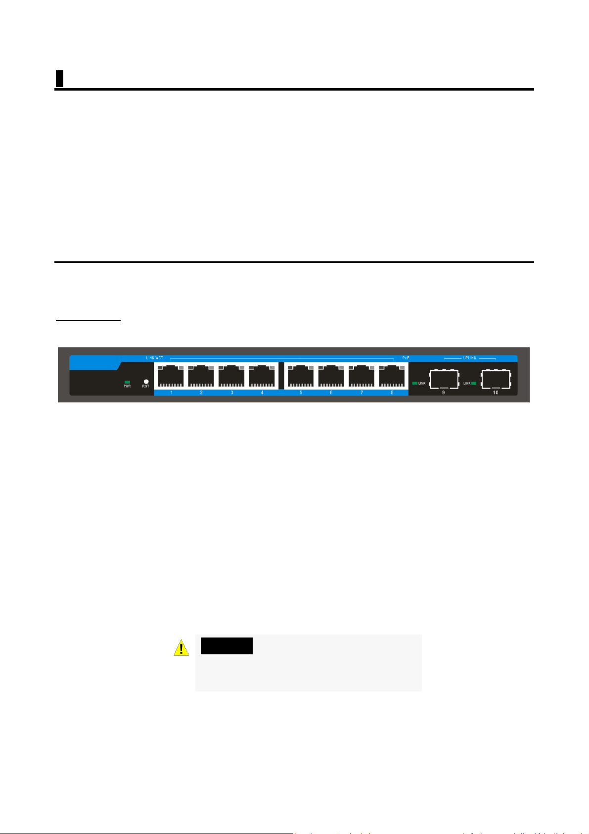
8 Port 10/100/1000Base-TX with 2 Gigabit SFP and 8 PoE L2+ Managed Switch
Front panel
PWR LED: The Power LED lights up when the Switch is connected to a power source.
Link/Act LED: The Link/Act LED flashes which indicates a network link through the
corresponding port. Blinking indicates that the Switch is either sending or receiving
data to the port.
PoE LED:
Green: Indicates the PoE powered device (PD) is connected and the port supplies
power successfully.
Light off: Indicates no powered device (PD) connected.
RST: By pressing the Reset button for 5 seconds the switch will change back to the
default configuration and all changes will be lost.
Warning: The SFP ports should use UL
listed Optical Transceiver product,
Rated Laser Class I. 3.3Vdc.
3
Page 6

Real panel
Grounding: use specialized ground lead connect
Connect the power adapter output terminal to this port. Supports input voltages
+44 ~ +57 VDC
4
Page 7
2 Hardware installation
This chapter provides unpacking and installation information for the Managed PoE
switch.
First step: open a seal
Open the shipping carton and carefully unpack its contents. Please consult the
packing list located in the User Manual to make sure all items are present and
undamaged. If any item is missing or damaged, please contact the local reseller for
replacement.
Switch 1pcs
Power adaptor 1pcs
AC power cord
Rubber feet 4pcs
Screws 6pcs
User manual 1pcs
If any item is found missing or damaged, please contact the local reseller for
replacement.
Second step: switch installation
For safe switch installation and operation, it is recommended that you:
Make sure power adapter connect with the POE switch
Make sure that there is proper heat dissipation and adequate ventilation
around the switch.
Do not place heavy objects on the switch.
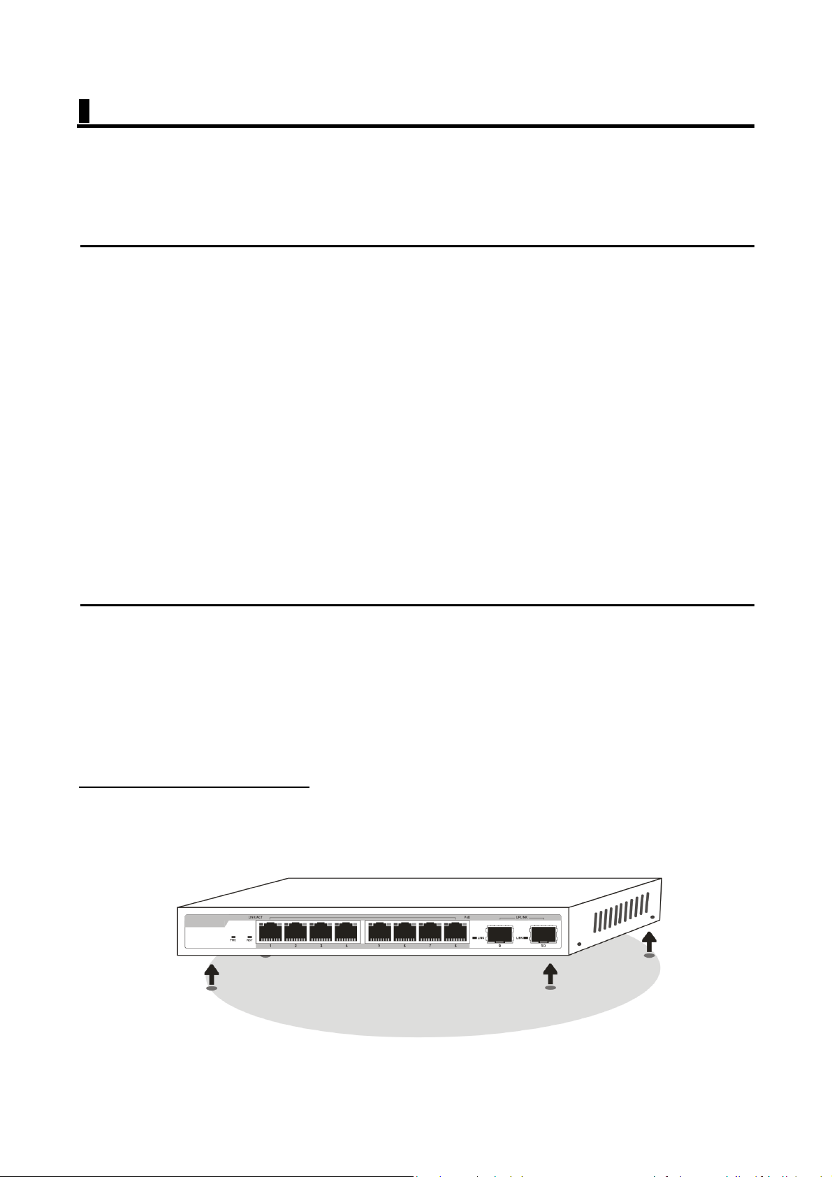
Desktop or Shelf Installation
When installing the switch on a desktop or shelf, the rubber feet included with the
device must be attached on the bottom at each corner of the device's base. Allow
enough ventilation space between the device and the objects around it.
5
Page 8
Wall mount Installation
Attach the mounting brackets to the switch's side panels (one on each side) and
secure them with the screws provided (please note that these brackets are not
designed for palm size switches).
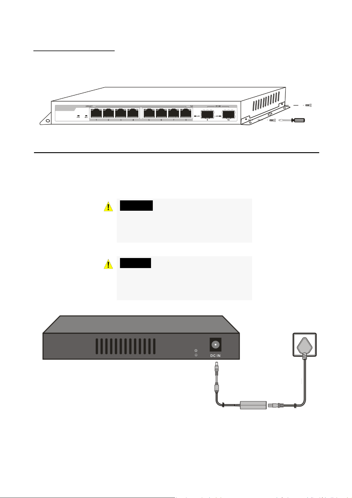
Third step: Connecting power supply
Using the AC power cord to connect to the power adapter, and then plug the output
terminal of the adapter into the DC IN socket on the back of the switch. (The AC
power outlet should be grounded)
Warning: Do not turn on the power
switch before power cables are
connected. Power surge may cause
damage to the Switch.
Warning: The installation instructions
clearly state that the ITE is to be
connected only to PoE networks
without routing to the outside plant.
6
AC Power Cord
DC Power Adapter
Page 9

Power failure
As a precaution, the switch should be unplugged in case of power failure. When
power is resumed, plug the switch back in.
3 Getting Started
This chapter introduces the management interface of Managed PoE switch.
Management Option
The Managed PoE switch can be managed through any port on the device by using
the Web-based management.
Each switch must be assigned its own IP address, which is used for communication
with Web-Based Management or a SNMP network manager. The PC should have an
IP address in the same range as the switch.
Please refer to the following installation instructions for the Web-based
Management.
Using Web-based Management
After a successful physical installation, you can configure the Switch, monitor the
network status, and display statistics using a web browser.
Supported Web Browsers
The embedded Web-based Management currently supports the following web
browsers:
Internet Explorer 6 or higher version
Netscape 8 or higher version
Mozilla
Firefox 1.5/2.0 or higher version
Connecting to the Switch
You will need the following equipment to begin the web configuration of your
device:
1. A PC with a RJ-45 Ethernet connection
2. A standard Ethernet cable
7
Page 10
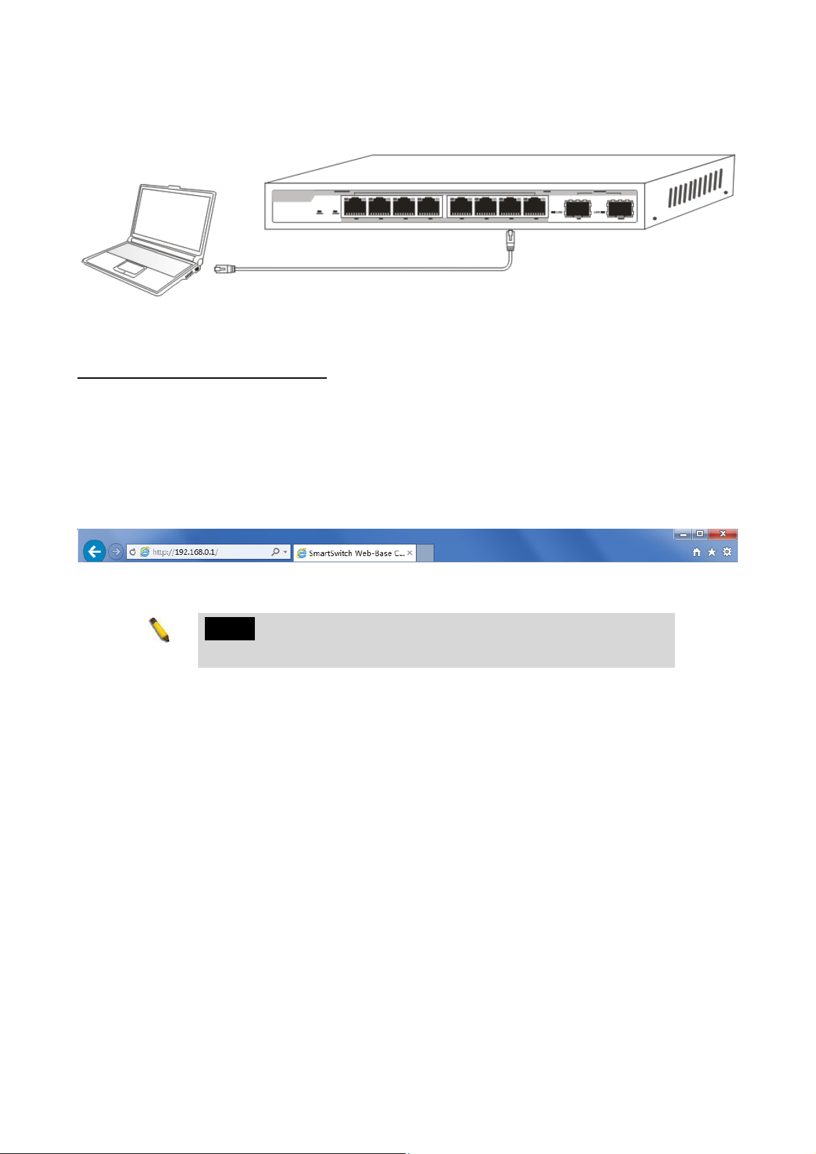
Connect the Ethernet cable to any of the ports on the front panel of the switch and
to the Ethernet port on the PC.
Network connection
Login Web-based Management
In order to login and configure the switch via an Ethernet connection, the PC must
have an IP address in the same subnet as the switch. For example, if the switch has
an IP address of 192.168.0.1, the PC should have an IP address of 192.168.0.x
(where x is a number between 2 ~ 254), and a subnet mask of 255.255.255.0. Open
the web browser and enter 192.168.0.1 (the factory-default IP address) in the
address bar. Then press <Enter>.
Enter the IP address in the web browser
NOTE: The switch's factory default IP address is
192.168.0.1 with a subnet mask of 255.255.255.0
To log in to the switch, the IP address of your PC should be set in the same subnet as
that of the switch. The IP address is 192.168.0.x (”x” is any number from 2 to 254).
Subnet Mask is 255.255.255.0.
8
Page 11
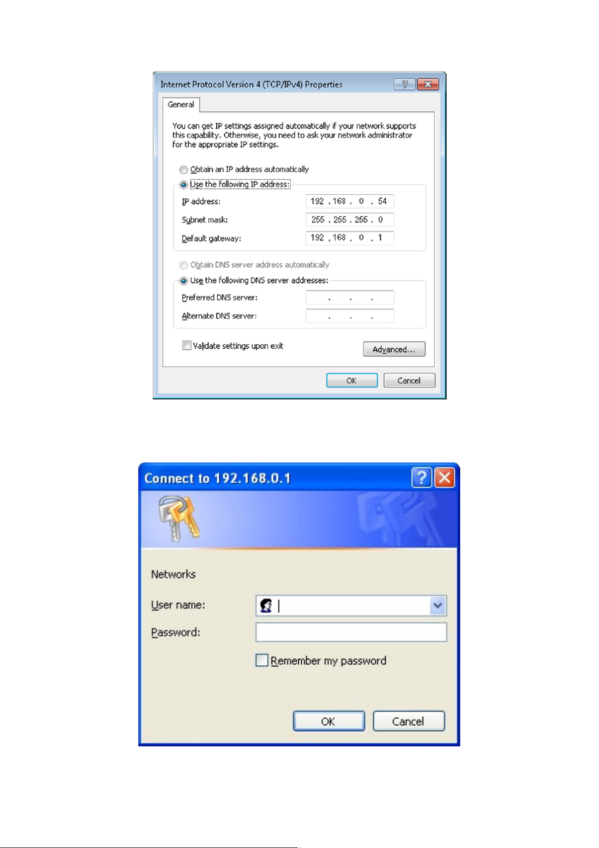
When the following logon dialog box appears, enter the password then click OK.
By default, the username is admin and the password is admin.
Logon Dialog Box
9
Page 12
1. WEB page elements
Shown in Figure 2, WEB page is mainly composed of three parts: title page,
navigation tree page and main page
Figure 2
Title page is used to display the logo
Main page is used to display the user from the navigation tree, select the page
2. The structure of Navigation tree
Figure 3 shows the navigation tree organizational structure.
Navigation tree is located in the lower left of each page, using the tree display nodes
of the WEB page; users can easily find the page you want to manage the WEB.
According to a different web page functionality can be divided into different groups,
each including one or more pages. Most of the navigation tree in the name of the
corresponding web page top of page title abbreviation.
10
Page 13
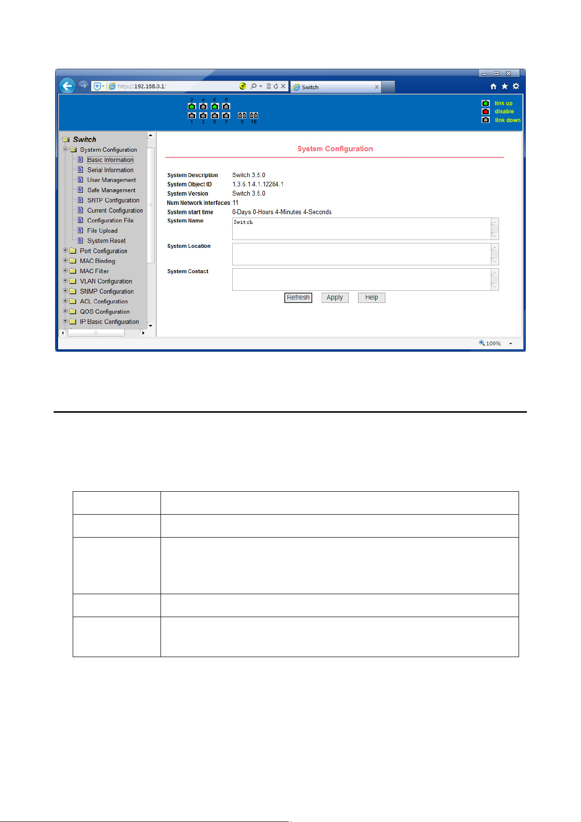
Figure 3
3. Page button Introduction
On the pages, here are some commonly used buttons, the role of these buttons are
generally the same, Form 2 on the role of these buttons are described:
Form 2:
button effect
Refresh Update all fields on the page
Apply Numerical value will be updated into the memory. Because
the error-checking should be implement by the Web Server,
before the user selects the button will be no error checking.
Delete Delete the current record
Help Open help pages, view the individual pages of the
configuration instructions
11
Page 14
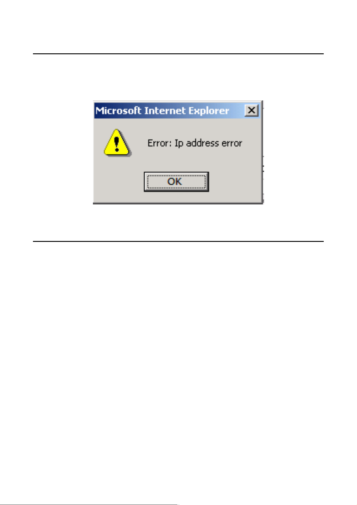
4. Error messages
If the switch WEB server error occurred while processing user requests, it will
display a dialog box in the corresponding error message. For example, Figure 4
shows an error message dialog box.
Figure 4
5. Entry Field
Some pages of the most left column in the table has an entry field, as shown in
Figure 5, through the field can access different rows in the table. When you choose a
lines for the field, which lines the corresponding information is displayed in the first
line, then only the line can be edited, the line also known as the activities line. A
time when it was first loaded, it shows the filed new, activity line is empty.
If want to add a new line, should select new from the drop-down menu of entry field,
enter the new line’s information, and then press apply button.
If you want to edit the line already exists, it is necessary select the appropriate line
number of the drop-down menu, according to need to edit the line, and then press
the apply button, you will see a corresponding change in the table displayed.
If you want to delete a row, select the line number accordly from entry field’s dropdown menu, then press the delete key, this line will disappear from the table.
12
Page 15
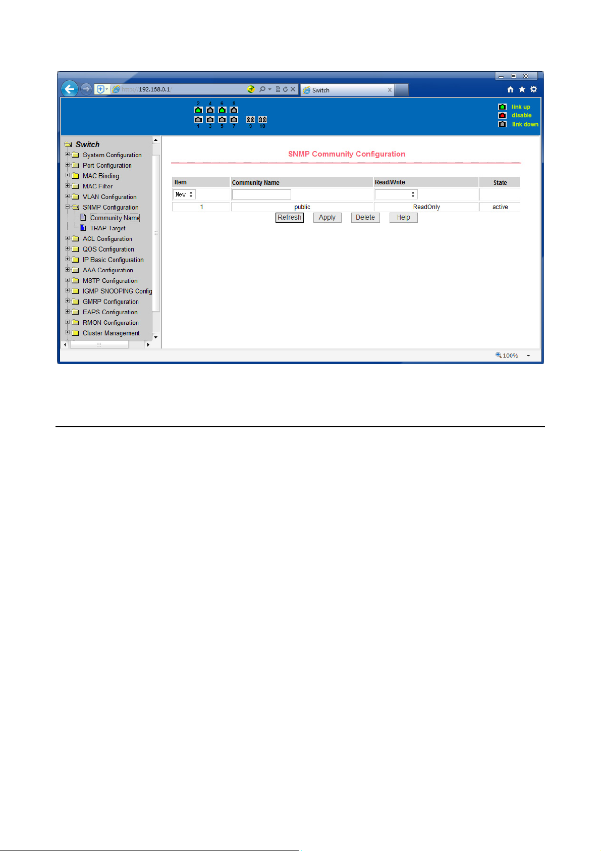
Figure 5
6. Status Field
Some pages of the most right column in the table there is a state field, as shown in
Figure 6, the field displays the line status. Since all row state changes are processed
in-house, so the status field is read-only. Once the line information of the entry filed
into force, the line will automatically become the active state the status active.
13
Page 16
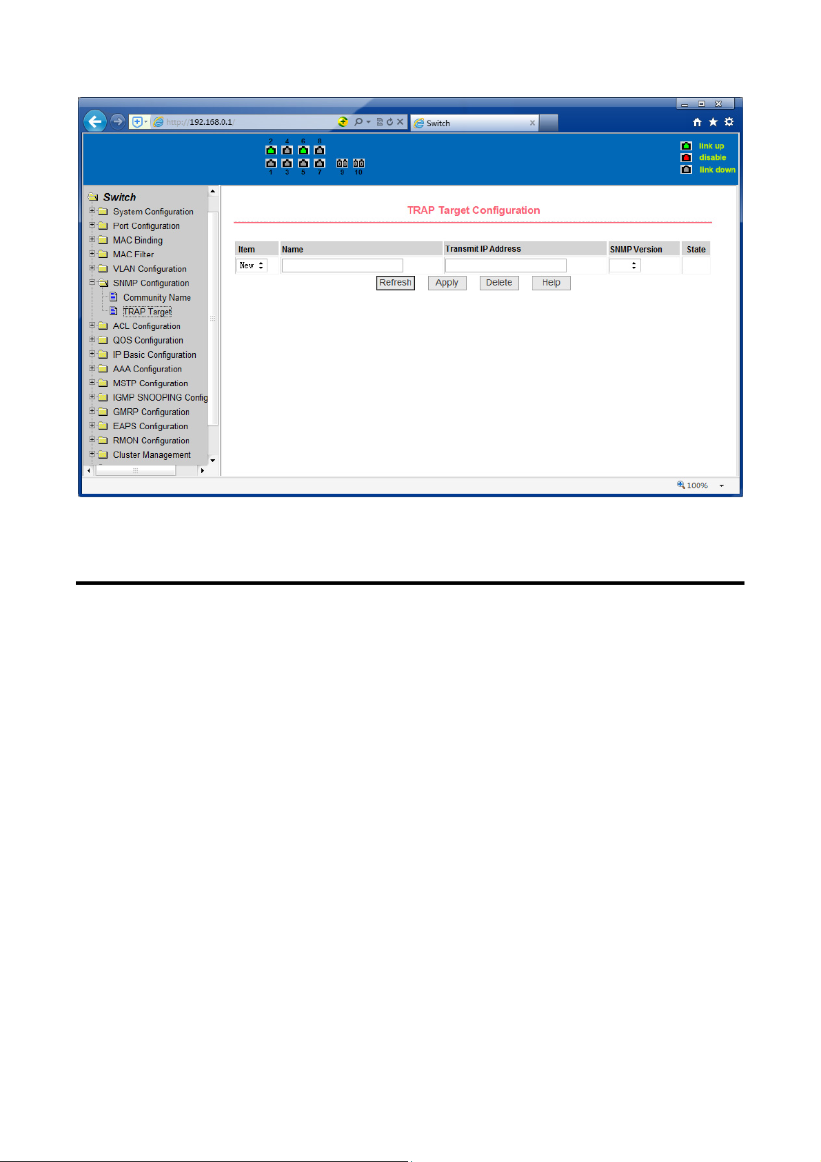
Figure 6 the web page of status field
WEB page introduction
Switch switches WEB pages organized into groups, each including one or more of
the WEB pages. The following are introduced one by one on each page.
14
Page 17
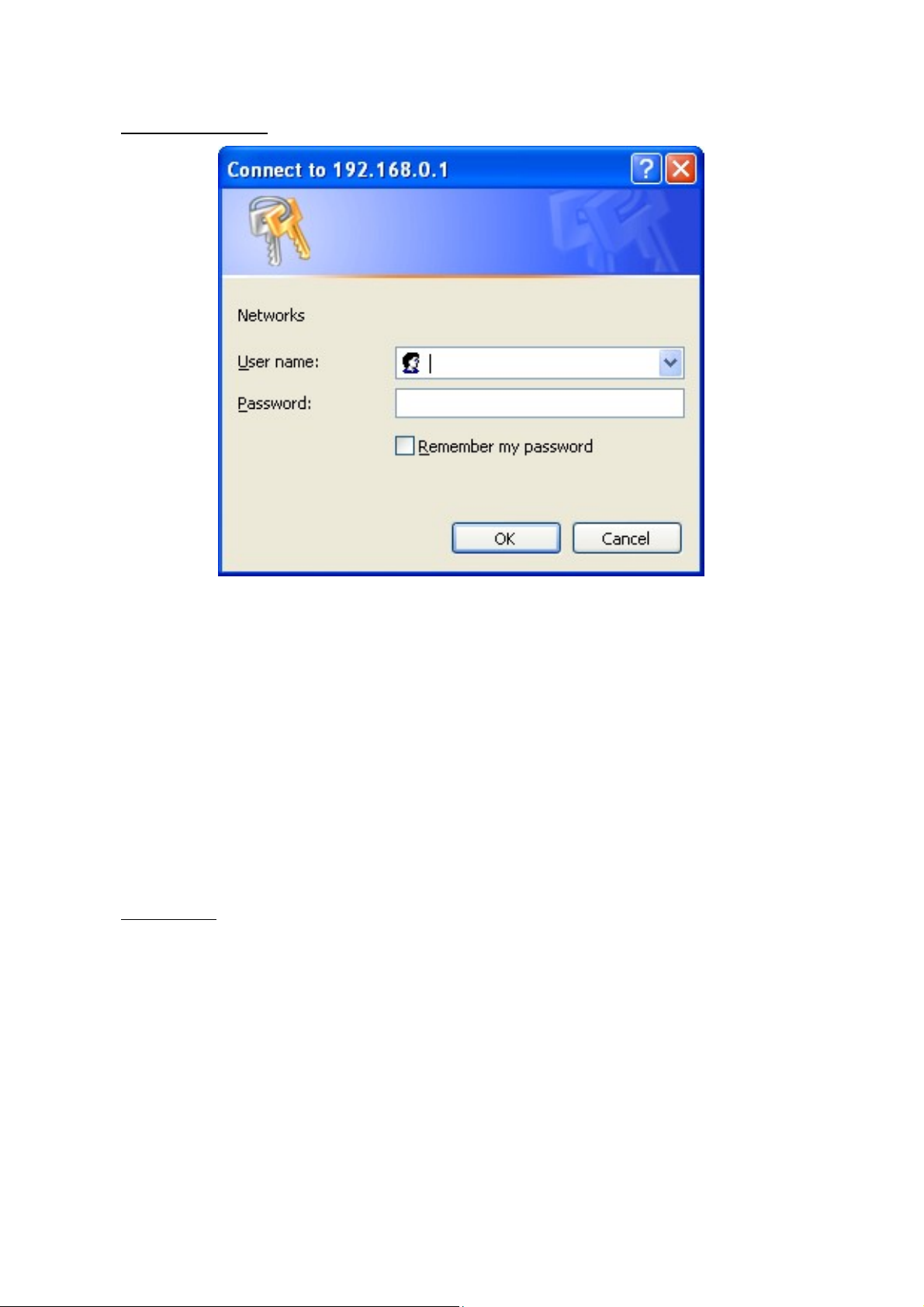
1. Login dialog Box
Figure 7 WEB browsing session of the login page
Figure 7 shows the login dialog box, the logon dialog box will be displayed while the
user login the web page at the first time. When the user filled out the correct user
name and password, then click the Enter button can log on to the switch Web server.
Passwords are case-sensitive, the anonymous user password can be maximum set
up to 16 characters, while the multi-user name and password can be set up to 11
characters. Switch switch default user name is the anonymous user name admin,
default password for the anonymous user's password, the default username is
admin and password is admin.
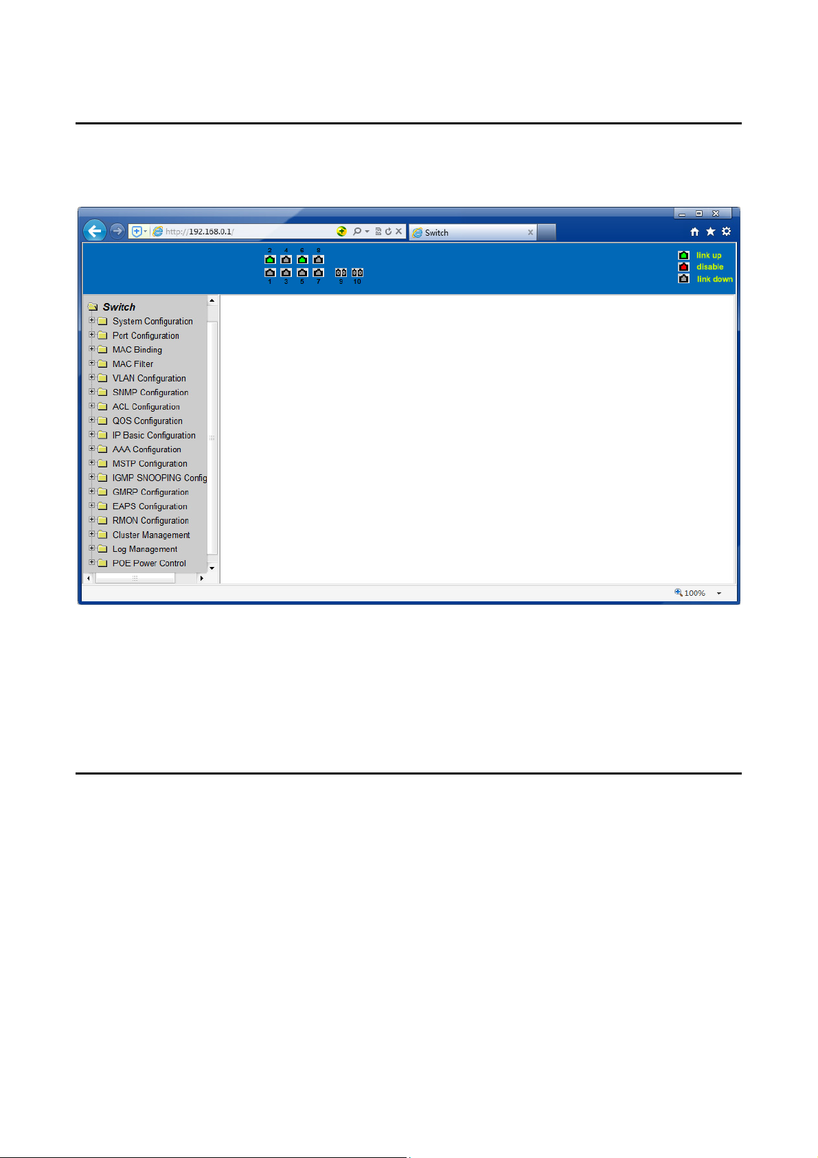
2. Main Page
Figure 8 shows the WEB main page of tico Switch switches. This page will be
displayed after the user logs in web pages
15
Page 18
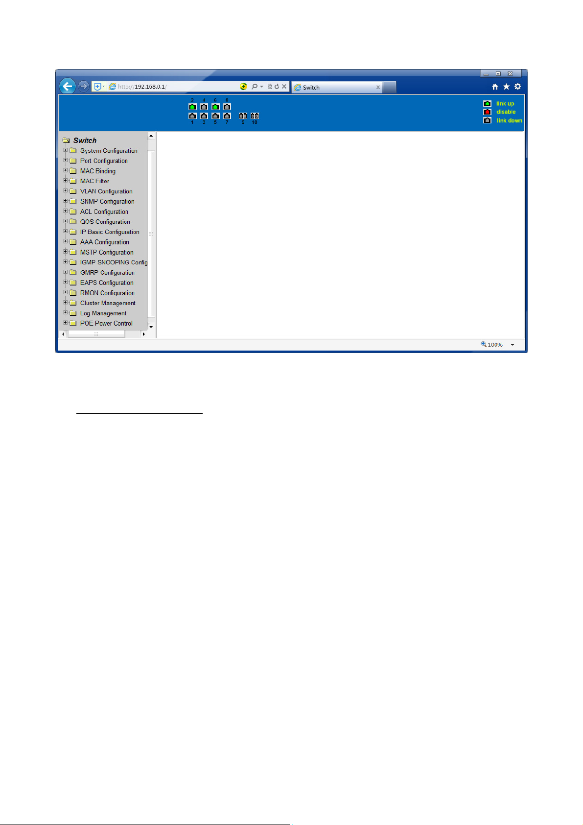
Figure 8 Switch switches main page
3. System Configuration:
(1) Basic information page
Figure 9 is the basic information of configuration page, users can configure the basic
information for the switch.
System Description displays the description of the relevant parameters of system.
System descriptor ID display system in the network identity management.
The system version number is displayed the current software version number of
switches. The number of switches interface displays the current number of
interfaces in the switch.
The system start-up time display switches from start to the present time. The
system name as the switch’s system name in the network, the user can modify the
system name.
The systematic location as the switch’s physical location showing at the network, the
user can modify the system locations system contact show the contacts person and
details of the current node, the user can modify the system contact.
16
Page 19
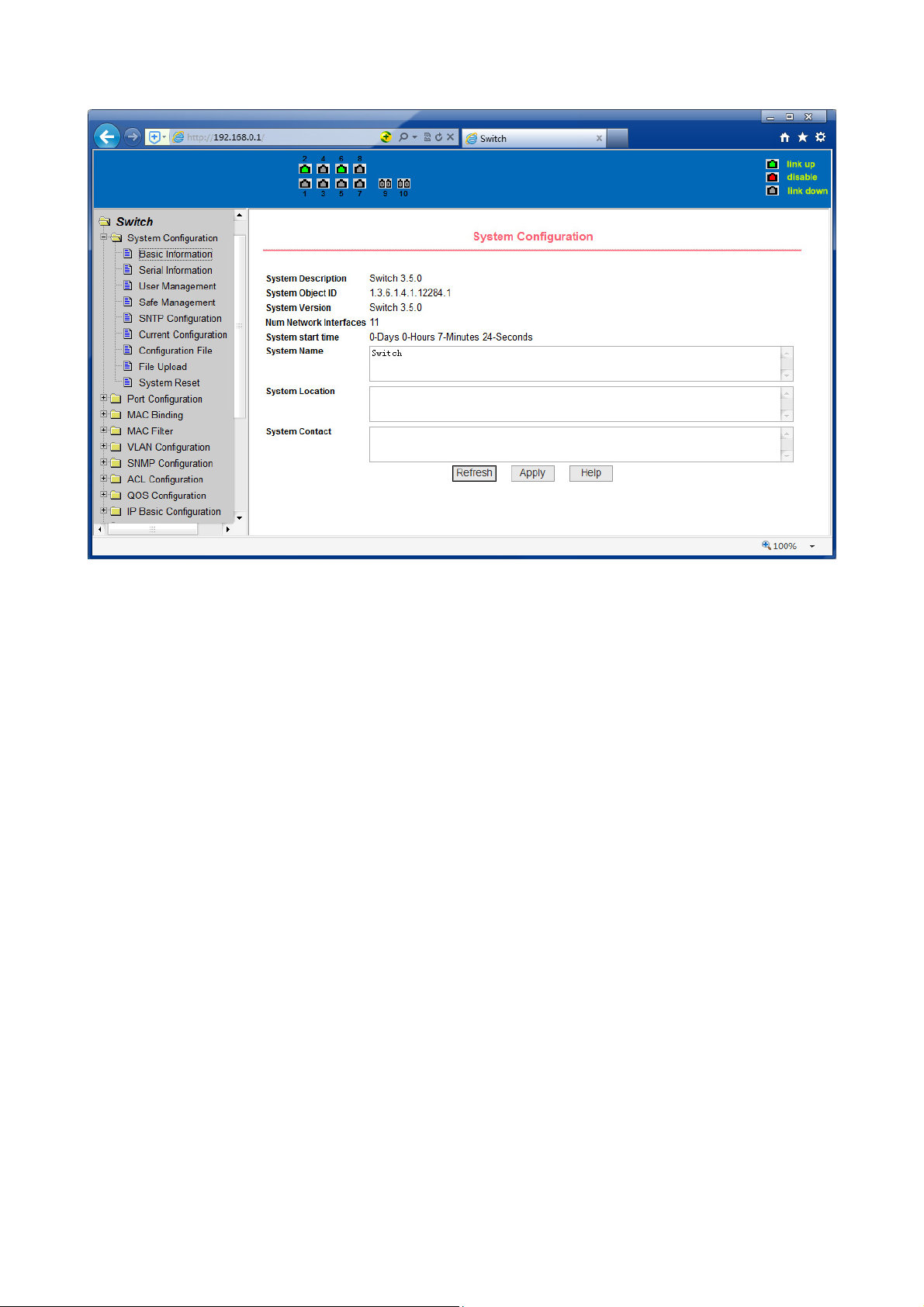
Figure 9 Basic information Page
(2) Serial port information page
Figure 10 is a serial port configuration page, the page displays serial baud rate and
other related information. When the host through the serial port terminals (such as
Windows, HyperTerminal) to the management of switches, serial console on the
COM port configuration must be consistent with this page information.
17
Page 20
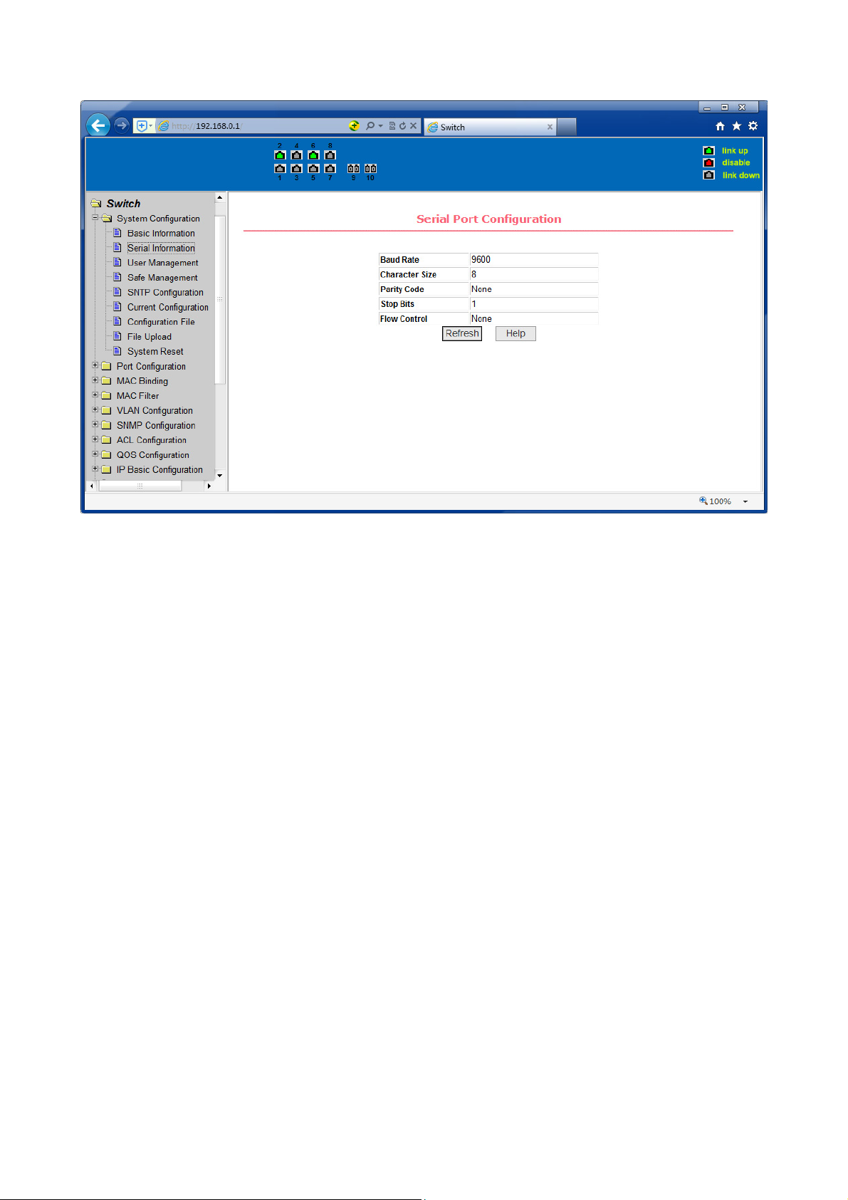
Figure 10 Serial port information page
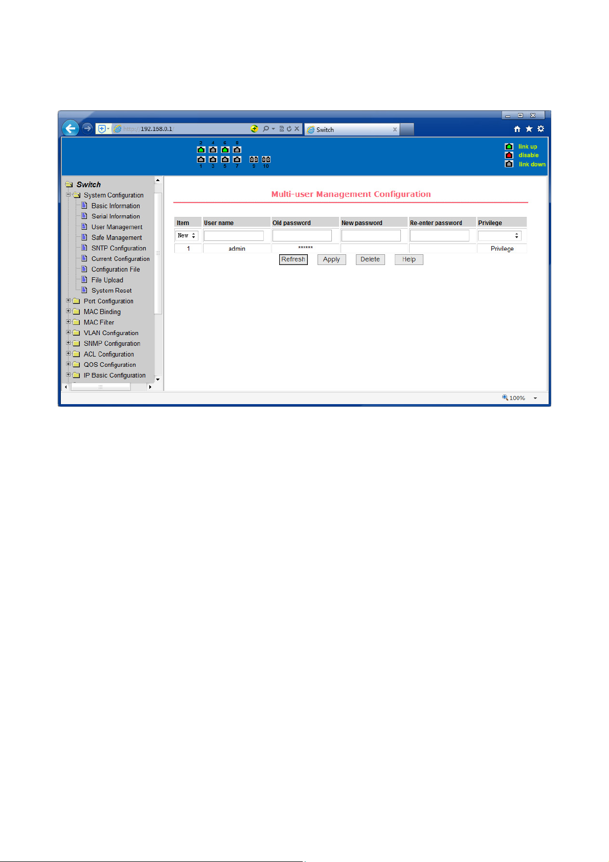
(3) User management page
Figure 11 is a user management page, the user can modify this switch anonymous
user (admin) password, Telnet and the Web without opening a multi-user, they all
use the same anonymous user's password. Passwords are case-sensitive, and can be
up to 16 characters. If you want to change your password, the user need to enter
the new password twice, once the user clicks the application button, the new
password is activated, then if the switch is not enabled multi-user, will display the
login dialog box (as shown in Figure 7), require the user to re - login the web page,
with a new anonymous user password.
Meanwhile through this page user can configure the multi-user, switch if in the
default is no multi-users that is, not enabled the multi-user management
functionality, at this time does not require multi-user login user name and password
authentication. For Telnet, when adding a user name, multi-user management
features were enabled, and when removed all users, multi-user management
functionality has been closed. For the Web, when adding a user name, if it is
privileged user, multi-user management functionality was enabled, when all of the
privileges users have been deleted, multi-user management functionality has been
closed. When the multi-user management features enabled, the anonymous user's
password will not take effect, log Telnet and the Web requires a multi-user user
name and password authentication. When the multi-user management function is
turned off, at this time if the configured anonymous user's password, log on Telnet,
18
Page 21
and Web need anonymous user's password authentication
Figure 11 user’s management page
(4) Security Management Page
Figure 12 is Security management configuration page, through the page's
configuration, the administrator can control network management services TELNET,
WEB and SNMP, you can open (enable) or off (disable) these services, these services
can be mounted up with standards IP ACL group, and the implementation of the
source IP address control, control access to the host of these services.
When the Switch default, TELNET, WEB and SNMP services are open and no ACL
filtering, that is, all hosts have access to the switch of these three services. If the
administrator for safety, do not want to provide one or several services, which can
shut down one or several services. If the administrator only hope that the specified
host could access one or several services, can do the ACL filtering for one or several
services. As a service to do ACL filtering, you need to open the service, and to select
an IP standard ACL group (1-99), the primary factor it’s the ACL group must be
present.
Note that, if the administrator on this page control the WEB services (such as closing
WEB Services) may cause users to no longer use the WEB page, then you can log
switches by other means and to control the use of WEB service allows users to WEB
page (such as the Open the WEB service).
19
Page 22
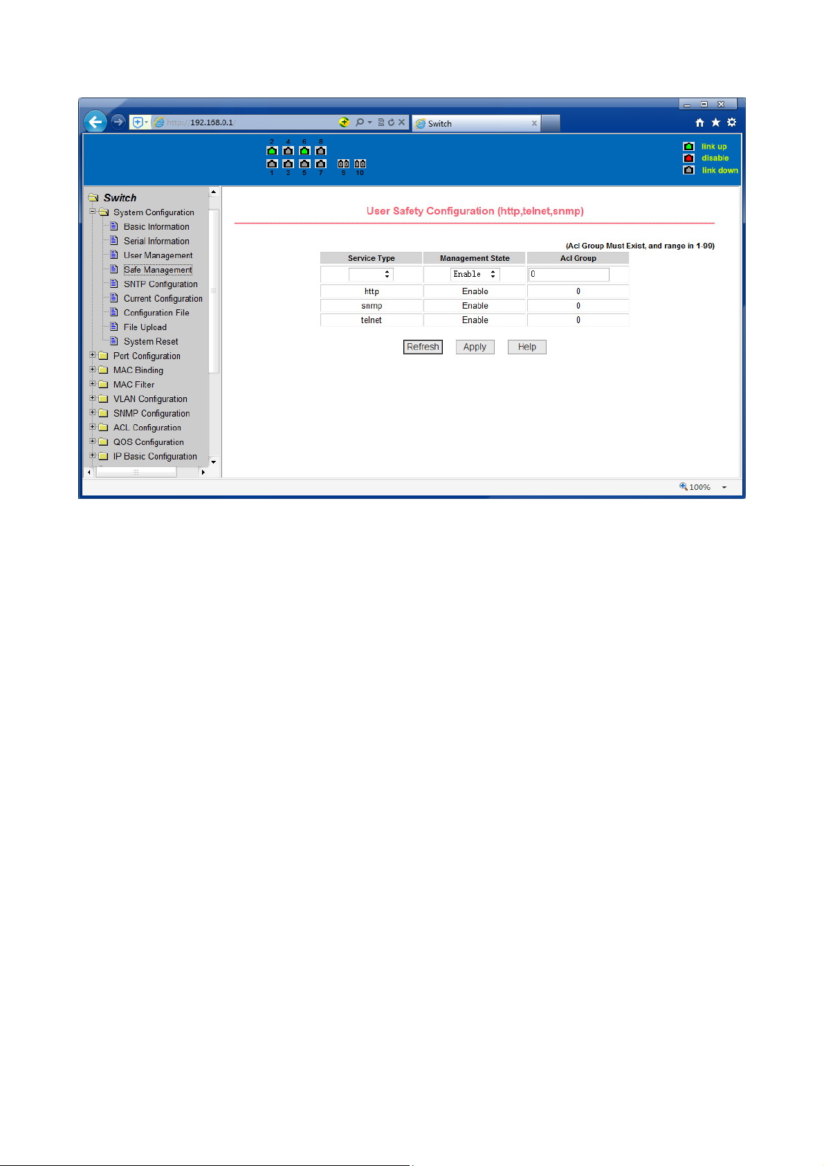
Figure 12 Security management page
(5) Configure the current page
Figure 13 is the current configuration page. The user can view the current
configuration of the switch on this page. Save key is to store the current system
configuration in the configuration file. Because the storage operation requires
erase& write FLASH chips, which take up some time. When the user was configured
on the page and hope to restart the switch from using these configurations are not
lost, you must exit the page before the current configuration page, click the Save
button.
20
Page 23

Figure 13 the current configuration page
(6) Configuration page
Figure 14 is profile configuration page. This page allows users to view the system's
initial configuration. The initial configuration is actually the configuration file in the
FLASH, when the configuration file does not exist in FLASH, the system starts using
the default configuration. Delete key to delete the configuration file in the FLASH.
Click the Delete button, will pop up a dialog box, that will prompts the user sure to
delete the configuration file or not, according to the dialog box to determine if it's
ok, otherwise click Cancel button. Download button is used to downloaded a
configuration file to the PC. Click to download button, will pop up a dialog box, users
select Save and save the configuration file directory path. Download the
configuration file names are as switch.cfg.
21
Page 24

Figure14 Configuration file page
(7) File upload page
Figure 15 is a file upload page; through this page a user can upload a configuration
file and mapping files to the switch. Click the Browse button to select the upload
configuration file or image file in the directory path on the PC. Click Upload button
upload a configuration file or image file, configuration file extension must be *. cfg,
image file must be provided by the manufacturer and the file name extension must
be *. img. Transmission before the return of the results page, please do not click on
other pages, or restart the switch; otherwise, the file transfer will lead to failure
caused by system crashes.
22
Page 25

Figure 15 File Upload Page
(8) System reset page
Figure 16 is system reset page, through these page users to restart the switch. When
you click on Restart button, will pop up a dialog box that prompts the user to
determine whether or restart the switch, If it is determined according to OK button,
otherwise click Cancel button. Restart will no longer open the Web page.
23
Page 26

Figure16 System reset page
4. Port Configuration
(1) Port configuration/port -display page
Figure 17 is the port configuration/port -display page. Users can enable or disable
the port to the page, set the port speed, or View all ports of the basic information.
To set a specific port, users need to select the appropriate port name on port dropdown menu. The default port status is up, can select the drop-down menu -down to
disable the port. Users can also choose to set the speed of the drop-down menu to
set the speed of the port, such as the mandatory half-duplex port 10M (half-10) and
so on. On this page the user can view all ports other basic information.
Figure 17 port configuration and port - display page
(2) Port Statistics Page
Figure 18 is the port statistics information page. To view a particular port, users
need to select the appropriate port name in the port drop-down menu. Users can
view the statistics information of send and receive packets on this page.
24
Page 27

Figure 18 Port Statistics Page
(3) Flow control page
Figure 19 is the flow control page. Users can enable and disable each port’s send
and receive flow control through this page.
Flow control by sending the side of the drop-down on or off to open or close the
sending side of flow control, flow control through the receiving side of the dropdown on or off to open or close the receiver-side flow control, while on and off also
shows the port to send side and receiving-side flow control is turned on or off.
25
Page 28

Figure 19 Flow control page
(4) Broadcast storm control page
Figure 20 is the Broadcast Storm Control page. This page is used to do the
suppression for configure port broadcast packets, multicast packets and DLF packet.
From the Port drop-down bar select to configure ports. Through the on and off key
to open and close the port broadcast suppression, multicast, DLF inhibition and
suppression. Inhibition rate is used to configure the port inhibition speed, range 11024000, unit kbits. The inhibition rate of the same port broadcast suppression,
multicast and DLF inhibition is the same.
26
Page 29

Figure 20 Broadcase Storm control Page
(5) Port speed limits page
Figure 21 is the port speed- limit page. This page is used to configure the port, send
and receive rate
From the Port drop-down bar select the configure ports. Bandwidth control of the
send data packets is used to configure and display the bandwidth control it, the
range is 1-1024000, unit kbits, enter into force after the key press applications. If the
port is not configured bandwidth control, shown as off. Cancel button is used to
cancel the corresponding data packet to send bandwidth control. Receiving data
packets are used to configure and display the bandwidth control of receive data
packets control, the range is 1-1024000, unit kbits, enter into force after the key
press applications. If the port is not configured bandwidth control, shown as off.
Cancel button is used to cancel the corresponding receiving data packets bandwidth
control
27
Page 30

Figure 21 Port speed limit page
(6) Port protection page
Figure 22 is the Port protection page. This page is used to configure the port for the
protection port.
If the port is configured as a protected port, the ports cannot exchange the data
with each other, protected port only with non-protected port for data exchange.
28
Page 31

Figure 22 protected port page
(7) Port Learning restrain page
Figure 23 is the port learning restrain page. This page used to restrict the port can
learn of the MAC address of the number, range is 0-8191. The default value is 8191,
also is the maximum that the port is not configured the learning restrain
Figure 23 Port Learning restrain page
29
Page 32

(8) Port Trunking configuration page
Figure 24 is the port trunking configuration page. This page allows the user to
configure the port trunking. This page consists of four parts: port trunking ID
selection, port trunking method selection, configurable ports and group of members’
port.
To create or modify the port trunking, the user needs to select a port trunking ID,
port trunking ID from 1 to 8. The user clicks the list box the appropriate port
trunking ID, the port trunking of information displayed in the group port. To create a
Trunk group, select the appropriate ID in the port trunking ID, click the button
"Trunk ID Settings." To set the port trunking method, select one port trunking
method, click the button "polymerization Settings." To increase the trunking ports,
the port can be configured to select the trunking port in the configurable, click on "
member port =>" "key. Aggregation from the existing port to remove a port group
member ports in the trunking port selected, click on " unmenber port<="key. To
delete the entire TRUNK group, then click the "Delete trunk group" button.
In page configuring process, at least one Trunk has been established then
polymerization settings can take effect; configured Trunking method is also applied
to all on the Trunk groups; in that already exist on the Trunk can add or remove Port
members; in the absence of the port members situation can deletee a Trunk Group.
The switch provides six types of port aggregation: based on the source MAC address,
based on the destination MAC address, based on the source and destination MAC
addresses, based on the source IP address, based on the destination IP address,
based on the source and destination IP addresses.
The switch supports a maximum of eight port aggregations. Up to eight trunks can
be configured, and each group can aggregate up to eight ports.
30
Page 33

Figure 24 Port Trunking configuration page
(9) Port mirroring configuration page
Figure 25 is the port mirroring configuration page. The page allows users to
configure port mirroring. Port mirroring through the mirror port to monitor the data
packets of being mirrored output port and the data packets of being mirrored input
port. Mirroring Port can only choose one, being mirrored output port and being
mirrored input port can select multiple. This page consists of four components:
monitor port, configurable port, monitoring direction and mirror configuration
information. When you start to configure a mirror port, firstly configured mirroring
port from monitor ports, mirror ports can only have one, and then select the mirror
port from the configurable port, select the monitor direction, and press the
application key to entry into force, the results is displayed in the mirrored
configuration information.
When choose the RECEIVE in direction of monitor, said monitor data packets
received, TRANSMIT, said monitor data packets sent, BOTH that monitor all data
sent and received packets, NOT_RECEIVE to cancel monitoring received data packets,
NOT_TRANSMIT to cancel monitor send data packets, NEITHER cancels monitor data
packets received and sent, that is canceling monitor port.
31
Page 34

Figure25 Port mirroring configuration page
5. MAC binding
(1) MAC binding configuration page
Figure 26 is the MAC binding configuration page. This page is used to achieve the
port and MAC address binding.
MAC entries on the page is used to enter the MAC address binding, VLAN ID entry is
used to enter the MAC address of VLAN
32
Page 35

Figure 26 the MAC binding configuration page
(2) MAC binding automatic conversion page
Figure 27 is the MAC binding automatic conversion page. This page is used to
achieve the port MAC address auto-binding. Shows the hardware switch on the lay 2
the exist port dynamic MAC address and affiliated VLAN. Can choose one of the
entry and convert it into static binding.
33
Page 36

Figure 27 the MAC binding automatic conversion page
6. MAC filtering
(1) MAC filtering configuration page
Figure 28 is the MAC filtering configuration page. This page is used to configure the
ports on the MAC address filtering.
MAC entries on the page is used to enter the MAC address filtering, VLAN ID entry is
used to enter the MAC address affiliated VLAN.
34
Page 37

Figure 28 the MAC filtering configuration page
(2) MAC filtering automatic conversion page
Figure 29 is the MAC filtering automatic conversion page. This page is used to
achieve the port MAC address auto-binding.
Shows the hardware switch on the lay2 the exist port dynamic MAC address and
affiliated VLAN. Can choose one of the entry and convert it into static filtering
configuration
35
Page 38

Figure 29 the MAC filtering automatic conversion page
7. VLAN Configuration
(1) VLAN information page
Figure 30 shows the current VLAN information page. This page is read-only page
displays the current VLAN configuration information l, including the VID, state and
port members. Select VLAN from the drop-down VID, shows the port information of
the Port VLAN members.
A port may not be a member of VLAN, which can be VLAN-tagged or untagged
members. The meanings of characters please see the following info:
t tagged the port is the VLAN tagged member
u untagged the port is the VLAN untagged member
36
Page 39

Figure 30 VLAN information page
(2) Static VLAN configuration page
Figure 31 is the static VLAN configuration page that allows users to create VLAN.
If you want to create a new VLAN, the user input VID on activity line, ranging from 2
to 4094. VLAN name is generated depend on VLAN ID and cannot be modified. Click
Apply button, then the list box displays the user-created VLAN's VID and VLAN name.
Switch by default created VLAN1, and VLAN1 cannot be removed
If you want to delete a VLAN, the user needs to click the appropriate VLAN of the list
box. The VLAN will be displayed in the activity line, click the Remove (Delete) key to
delete the VLAN, the same time, the information of the VLAN to remove from the
list box.
37
Page 40

Figure 31 the static VLAN configuration page
(3) VLAN port configuration page
Figure 32 is a VLAN port configuration page, which is used to configure the VLAN
port configuration and display results. This page mainly consists of eight parts: port,
mode, all current VLAN, port-owned VLAN, key "default VLAN =>", "tagged =>",
"untagged =>" and "non-members =>".
Port is defined a designated port that will configure the VLAN
Mode Access designated the VLAN mode as the ACCESS mode, under this mode, the
port default VLAN is the untagged member of VLAN1, the port's default VLAN is 1.
Hybrid specified port VLAN mode HYBRID model, in this mode, the port default
VLAN is the untagged member of VLAN1, the port's default VLAN is 1. Trunk
specified port VLAN mode is TRUNK mode, in which the port VLAN mode, the
default is VLAN1 a tagged member of the port's default VLAN is 1.
All current VLAN that has been created VLAN, also it’s can be configured VLAN, the
user from the list select VLAN, can be multiple-choice.
VLAN Port-owned shows the results of VLAN port configuration, [p] indicates that
the port VLAN is the default VLAN, [t] that the port is a VLAN tag members, [u] that
the port is not tagged VLAN member. When you remove VLAN, the user from the list,
select the VLAN, can be multiple-choice.
38
Page 41

Button "default VLAN =>" to configure port the default VLAN, selected one VLAN
from the current all the VLAN.
Button "tagged =>" Configured port is designated as a tagged member of VLAN,
selected one or more VLAN from the current all VLAN.
Button "untagged =>" Configure VLAN port is a designated member of the untagged,
selected one or more VLAN from the current all VLAN.
Button "non-members <= to delete the port from the specified one or more of the
VLAN, no longer a member of the VLAN, from the port affiliated VLAN to selected
one or more VLAN.
Figure 32 The VLAN port configuration page
8. SNMP Configuration
(1) SNMP share body configuration page
Figure 33 is a shared body of SNMP configuration page that allows users to
configure the switch common body's name and read and write access, A total of 8
entries can be configured
39
Page 42

By default, the switch there is a share name as named public, the common body is
read-only access. With this correspondence, the activities of this page is only one
entry, shared body names are public, access is read-only access. When the switch
through SNMP for network management, you need to configure a read-write
permissions to the shared body.
Figure 33 a shared body of SNMP configuration page
(2) TRAP target configuration page
Figure 34 is the TRAP target configuration page that allows users to configure the
workstation to receive TRAP messages as well as the IP address of TRAP protocol
packets of some of the parameters.
In the configuration entry, the name used to enter the TRAP name, IP address used
to enter the target address, SNMP version used to select the version of the TRAP
packet, if you set successful, it will show in the state to active. If the configuration
was successful, SNMP TRAP functions will take effects, in the event of link up or link
down, the switch will automatically send a TRAP packet to the target address
40
Page 43

Figure 34 the TRAP target configuration page
9. ACL Configuraion
(1) IP Standard ACL configuration page
Figure 35 is the IP standard ACL configuration page. Users can through this page to
build ACL standard IP-rule base. User can select an ACL group number, in the group
to create one or more rules. In a rule can match only the source IP address field
(with mask). The standard IP rules to control the source IP address packet
forwarding.
41
Page 44

Figure 35 the IP standard ACL configuration page
Users to configure the rules, the source IP address must be in with a mask, the rule
can match the collection of IP addresses. The address mask is use anti-code, if the
rule were to match the IP address range 192.168.0.0 to 192.168.0.255, then the IP
address can be
192.168.0.1, and its mask of 0.0.0.255.
Users to configure the rules, each rule must have a filter mode: allow or deny.
The user to create a rule in the group, the system will automatically give the rule a
rule number, when to delete a rule in the group 1 rules, other rules remain
unchanged, the system will automatically give the rule a rule group sort. If the user
wants to delete the entire rule set, you can first select all, and then click the delete
key.
(2) IP Extended ACL configuration page
Figure 36 is the IP extended ACL configuration page. The extended IP group is an
extension of the standard IP rules. Control the packet forwarding via source IP,
Destination IP, IP protocol type and service port.
42
Page 45

Figure 36 the IP Extended ACL configuration page
(3) MAC IP ACL configuration page
Figure 37 is the MAC IP ACL configuration page. IP MAC group can be the IP packet
source and destination MAC address and source and destination IP address control.
Figure 37 the IP Extended ACL configuration page
43
Page 46

(4) MAC IP ACL configuration page
Figure 38 is the MAC IP ACL configuration page, IP MAC group can be the IP packet
source and destination MAC address and source and destination IP address control.
Figure 38 the IP Extended ACL configuration page
(5) MAC ARP ACL configuration page
Figure 39 is the MAC ARP ACL configuration page. ARP group can be the type of the
operation of the ARP packet, the sender MAC and the sender IP control.
44
Page 47

Figure 39 the IP Extended ACL configuration page
(6) ACL information page
Figure 40 is the ACL information page, which displays the current ACL rules
configured in all the information.
Figure 40 is the ACL information page
45
Page 48

10. QoS Configuration
(1) QoS Apply Configuration Page
Figure 41 is a QoS Apply configuration page.
Figure 41 QoS Apply configuration page
(2) QoS Schedule Configuration Page
Figure 42 is a QoS Schedule configuration page.
46
Page 49

Figure 42 QoS Schedule configuration page
11. IP Basic Configuration
(1) VLAN Interface Configuration Page
Figure 43 is a VLAN interface configuration page, users can configure the VLAN
interface through this page, delete VLAN interfaces, configure the interface IP
address, remove the interface IP address, and view interface information. VLAN
already exists can only be set when the interface can only be configured on the
interface set interface address.
47
Page 50

Figure 43 VLAN interface configuration page
Switch switch in the default have a VLAN1 interface, the interface can not be
deleted. One can only configure a VLAN interface.
(2) ARP configuration and display page
Figure 44 is the ARP configuration and display page, this page can display all of the
information of the ARP table switch, while users can configure a static ARP entries
on this page, delete ARP entries, and revised the dynamic ARP table entry to a static
ARP table entry.
When a user configure a static ARP entry, the need to enter the IP address and MAC
address, MAC address must be a unicast MAC address, and then click Add button.
When a user delete an ARP entry, you can choose to delete an IP-ARP table entry,
remove a segment of the ARP table entry, delete all of the ARP table entry, delete all
dynamic ARP table entries and delete all of the static ARP table entry. For the
deletion of an IP-ARP table entries, or delete a segment of the ARP table entry
required to enter in the input box, specify the IP address or IP network segment.
Then click the Delete button
When dynamic ARP table entry was revised to a static ARP table entry, you can
choose to a particular network segment or all of the dynamic ARP table entry was
revised to a static ARP table entry. For the situation to a network segment is
required in the input box, enter the specified network segment. And then click Apply
button
48
Page 51

Figure 44 the ARP configuration and display page
(3) Host Static Routing configuration page
Figure 45 is the host static route configuration page, the user can through this page
to add, delete static routing switch hosts. By default, the switch is not configured to
host a static route, the user can configure the default route through this page, that
is the purpose of address/subnet prefix is 0.0.0.0/0 routing
Figure 45 the host static route configuration page
49
Page 52

12. Certification. Authorization. Accounting (AAA) configuration
(1) Radius Configuration Page
Figure 46 is the Radius configuration page, users can configure with the Radiusrelated information, you can set information includes:
1. Be sure to set the Radius server's IP address before do the authentication
and accounting in this field
2. Optional Radius server IP address, if there is spare Radius server can set this
field.
3. Authentication UDP port, the default value is 1812, the user generally do not
need to modify this field.
4. Whether to activate the , the default is to start, and when you do
authentication and accounting in general to start charging.
5. Accounting UDP port, the default value is 1813.
6. Shared secret key is used to setting the shared encryption password between
the switch and the Radius server, so be sure to set the authentication and
accounting in this field, and with the same settings on the Radius server.
7. Vendor-specific information, the users typically do not need to modify this field.
8. NAS ports, NAS port type, NAS type of service, these three values do not
change in general.
9. Whether to on or off the roaming feature of Radius.
Figure 46 the Radius configuration page
50
Page 53

(2) 802.1x Configuration Page
Figure 47 is the 802.1x configuration page, users can configure 802.1x related
information on this page, including:
1. Whether to activate the 802.1x protocol, when doing authentication and
accounting must be to start 802.1x protocol.
2. Switch is to adopt a common authentication method or the expansion of
authentication.
3. Whether to open re-authentication function, the default is not open. When
you do authentication and accounting based on the actual circumstances.
Open the re-authentication feature will make users more reliable when using
the authentication and accounting, but it will slightly increase the network
traffic.
4. Setting re-certification time interval, only to re-open the case of
authentication to be valid, the default is 3600 seconds, when you do
authentication and accounting based on the actual situation to set the value,
but the value is not too small.
5. Quiet Period Timer, users typically do not need to modify this field.
6. Tx-Period Timer, users typically do not need to modify this field.
7. Server timeout timer, users typically do not need to modify this field.
8. Supplicant timeout timer, users typically do not need to modify this field.
9. Max Request number, users generally do not need to modify this field.
10. Showing Reauth Max size.
11. Client Version, the client version number.
12. Check Client; whether the certification passed then examine the client's
regular flow of packets.
51
Page 54

Figure 47 the 802.1x configuration page
(3) 802.1x port configuration page
Figure 48 is the 802.1x port configuration page, the user through this page to
configure the support 802.1x port mode and hosts of the largest, at the same time
you can view each port 802.1x configuration. 802.1x port model includes four types:
N/A State, Auto state, Force-authorized state and Force-unauthorized state. When a
port needs to do 802.1x Authentication, need to set Auto state, if not do
authentication to access the network, to set N/A state, the other two states are
rarely used in practical applications
52
Page 55

Figure 48 the 802.1x port configuration page
Doing 802.1x authentication, port access, the default maximum host number is 100,
the user can modify this field, the biggest support to the 100.
(4) 802.1x user authentication information page
Figure 49 is a 802.1x user authentication information page, the user can see through
this page, under a certain port access for all users of the state information
53
Page 56

Figure 49 802.1x user authentication information page
13. Spanning Tree Protocol configuration
(1) MSTP global configuration page
Figure 50 is the MSTP global configuration page, through which you can configure
some MSTP related information, mainly including:
Whether to enable MSTP.
Configure the bridge priority. Devices with lower priority are more likely to be
the root bridge.
Enable BPDU filtering function on the port in the portfast bpdu-filter default
state.
Enable BPDU guard function on the port in the portfast bpdu-guard default
state.
Configure the forwarding delay.
Configure the interval for sending MSTP Hello packets.
The errdisable mechanism is started. When a port that starts a BPDU guard
receives a BPDU, it starts the errordisable timer. errordisable restarts this port
after the configured timeout.
Configure errordisable timeout time.
Configure the number of seconds the switch waits to receive spanning tree
configuration information before triggering a reconfiguration.
Configure the number of hops specified before a BPDU is dropped in a domain.
54
Page 57

Start or shut down and cisco compatible spanning tree protocol.
Figure 50 MSTP Global Configuration Page
(2) MSTP port configuration page
Figure 51 is the MSTP global configuration page. Through this page, you can
configure some MSTP related information, mainly including:
Select the port to be configured.
Configure a port as a portfast port to enable the port from the blocking state to
the forwarding state, bypassing the listening and learning states.
Open the BPDU filter on the selected port.
Enable BPDU guard on the selected port.
Enable the root guard function, and do not accept BPDU packets with a higher
priority than the bridge. Specify the switch as the root switch.
Configure the connection type. Point-to-point: The type of connection is point-
to-point, allowing fast transition of the port status. Shared: Connection type is
shared, does not allow rapid conversion of port status, to go through the
calculation process of 802.1D to determine the status of the port.
Configure the cist priority of the interface. Range 0-240, can only be a multiple
of 16. The default is 128.
Configure the cist path cost. Range 1-200000000. The default is 20000000.
Lower path costs are more likely to be roots.
Configure the type of protocol packets to be sent.
55
Page 58

Figure 51 MSTP Port Configuration Page
(3) MSTP configuration information page
Figure 52 is the MSTP configuration information page, through which you can view
some MSTP related information
Figure 52 MSTP Configuration Information page
56
Page 59

14. IGMP SNOOPING configuration
(1) IGMP SNOOPING configuration page
Figure 53 is the IGMP SNOOPING configuration page, through which you can start
IGMP SNOOPING.
Figure 53 IGMP SNOOPING configuration page
(2) IGMP SNOOPING information page
Figure 54 is the IGMP SNOOPING information page, which allows users to view some
information about IGMP SNOOPING.
57
Page 60

Figure 54 IGMP SNOOPING Information page
15. GMRP configuration
(1) GMRP Global Configuration Page
Figure 55 shows the GMRP global configuration page. Users can enable GMRP
through this page.
58
Page 61

Figure 55 GMRP Global Configuration Page
(2) GMRP port configuration page
Figure 56 shows the GMRP port configuration page. You can use this page to enable
the GMRP port and view the port information.
Figure 56 GMRP Port Configuration Page
(3) GMRP state machine page
Figure 57 is the GMRP state machine page. Users can view the GMRP state machine
information through this page.
59
Page 62

Figure 57 is the GMRP state machine page
16. EAPS configuration
(1) EAPS configuration page
Figure 58 is an EAPS configuration page, through which you can configure some
EAPS related information, including:
Select an EAPS ring number.
Configure the operating node mode of an EAPS Domain.
Configure Primary Port of EAPS Domain.
Configure Secondary Port of EAPS Domain.
Configure a control VLAN for EAPS Domain.
Add one or more protected VLANs of the EAPS Domain.
Configure an EAPS Domain to periodically send HEALTH packets. Hello-timer
must be less than fail-time.
Set the fail-period timer of one EAPS domain to expire.
Enable or disable compatibility with Extreme devices.
Whether to enable
60
Page 63

Figure 58 EAPS Configuration Page
(2) EAPS information page
Figure 59 is an EAPS information page, through which users can view some EAPS
related information.
Figure 59 EAPS information page
61
Page 64

17. RMON configuration
(1) RMON statistics group configuration page
Figure 60 shows the RMON statistics group configuration page. You can use this
page to configure the RMON statistics group. Select a port from the drop-down list
to view/configure the RMON statistics group configuration for this port. When not
configured, the index number is 0, fill in the correct index number (range 1 to 100),
the owner is optional, you can configure RMON statistics group for the port. The
statistics table shows the port statistics from the successful configuration.
Figure 60 RMON statistics group configuration page
(2) RMON history group configuration page
Figure 62 shows the RMON history group configuration page. You can configure the
RMON history group through this page. Select a port from the drop-down list to
view/configure the RMON history group configuration for this port. When not
configured, the index number is 0, fill in the correct index number (range is 1 to 100),
interval, request Buckets, the owner is optional, you can configure the RMON
history group for the port. Interval refers to the time interval in seconds that the
data is collected. The range is 1-3600. The bucket is the allocated storage size and it
indicates how many records are stored. The range is 1-100. The statistics table
shows historical data that has been collected since the configuration was successful.
62
Page 65

Figure62 RMON history group configuration page
(3) RMON alarm group configuration page
Figure 62 shows the RMON alarm group configuration page. You can use this page
to create or modify an RMON alarm group. Select a configured alarm group from the
drop-down list to view/configure its information. Select New to create it. The index
number range is from 1 to 60, and the interval range is from 1 to 3600. In seconds,
the monitoring object must fill in the MIB node. The comparison method can choose
absolute (absolute value) or delta (change amount). In addition, the upper and
lower limit valves must be filled in. Value, event index, owner is optional. The alarm
value is read-only and shows the sampled value when the alarm was last issued. The
event index refers to the index number of the RMON event group and must be
configured in advance.
63
Page 66

Figure 62 RMON alarm group configuration page
(4) RMON event group configuration page
Figure 63 is the RMON event group configuration page. Users can create or modify
RMON event groups through this page. Select a configured event group from the
drop-down list to view/configure its information. Select New to create it. The index
number range is from 1 to 60. The description is a character string. Actions can
select none (no operation), log (log), snmp-trap (trap trap) or log-and-trap (log and
Trap alarm), Community names do not work in this device, owners are optional. The
last send time is read-only, showing the last time the event was sent.
64
Page 67

Figure 63 RMON Event Group Configuration Page
18. Cluster configuration
(1) NDP configuration page
Figure 64 shows the NDP configuration page. You can use this page to configure NDP.
The configurable information includes: selecting the port, enabling the NDP function
of the port, enabling the global NDP function, the interval for sending NDP packets,
and the aging time of the NDP packets on the receiving device.
For port selection, you can select the port as required and enable the port NDP
function. For NDP to operate normally, both global and port NDP must be enabled at
the same time.
Set the aging time of the NDP packets sent by the local device to the receiving
device. The valid time range is 1-4096 seconds. The default value is 180 seconds.
Set the interval for sending NDP packets. The valid time range is 1-4096 seconds and
the default is 60 seconds.
65
Page 68

Figure 64 NDP configuration page
(2) NTDP configuration page
Figure 65 shows the NTDP configuration page. You can use this page to configure
NTDP. The information that can be set includes: selecting the port, enabling the
NTDP function of the port, enabling the global NTDP function, the range of the
topology collection, the time interval of collecting the regular topology, the delay
time of the first port forwarding the packet, and the forwarding of the packet by
other ports delay.
For port selection, you can select the port as required and enable the NTDP function
on the port. For NTDP to operate normally, both global and port NTDP must be
enabled.
The range of topology collection is configured. The valid range is 1-6. In the default
configuration, the maximum number of hops from the most distant device to the
topology collection device is 3.
Set the interval for collecting the topology collection. The valid range is 065535 minutes. The default configuration is 1 minute.
66
Page 69

Set the delay for forwarding packets on the first port. The valid range is 11000 milliseconds. The default value is 200 milliseconds.
Set the delay for forwarding packets on the first port. The valid range is 1 to 100
milliseconds. The default value is 20 milliseconds.
Figure 65 NTDP configuration page
(3) Cluster Configuration Page
Figure 66 is the cluster configuration page. Users can configure the cluster and view
the cluster member table through this page. The information that can be set
includes: enabling the cluster function, configuring the management VLAN, the
address pool of the cluster, the interval for sending handshake packets, the effective
retention time of the device, the name of the cluster, the way to join the cluster,
and deleting the cluster.
To enable the cluster function, you must enable the cluster function before the
cluster function can run normally.
Configure a management VLAN. The valid range is 1-4094. The default configuration
is vlan1.
67
Page 70

Configure a private IP address range for member devices in the cluster. The valid
range of ip addresses is 0.0.0.0 to 255.255.255.255. The valid range of the mask
length is 0 to 32.
Set the interval for sending handshake packets. The valid range is 1-255 seconds.
The default is 10 seconds.
Configure the device's effective retention time. The valid range is 1-255 seconds and
the default is 60 seconds.
To set up a cluster, you need to configure the cluster name and choose to join the
cluster. There are manual and automatic joining methods. After establishing a
cluster, you can automatically switch to manual, but you cannot manually switch to
automatic. Manual mode can change the cluster name.
After a cluster is established, member devices and candidate devices can be viewed
in the cluster member table. You can delete member devices or add candidate
devices to member devices according to roles.
Figure 66 Cluster Configuration Page
68
Page 71

19. log management
(1) Log information page
Figure 67 is the Log information page. Users can enable and view various log
information through this page.
Figure 67 Log Information Page
Critical: Output critical level information.
Debugging: Outputs debug level debugging information.
Informational: Output information level debugging information.
Warning: Output warning level debugging information.
ALL: Output all log information
20. PoE port configuration
(1) PoE port Configuration Page
Figure 68 is the PoE port configuration/PoE-display page. Users can enable or
disable the port's PoE function to the page, or view all ports of PoE
information.
Information can be seen in the following tables:
69
Page 72

1. Status: Enable means PoE function is available
Disable means PoE function is close.
2. Operation: Displays the PoE ports ON or OFF
Figure 68 the PoE port configuration page
Hereby Assmann Electronic GmbH, declares that the Declaration of Conformity is part of the shipping
content. If the Declaration of Conformity is missing, you can request it by post under the below mentioned
manufacturer address.
www.assmann.com
Assmann Electronic GmbH
Auf dem Schüffel 3
58513 Lüdenscheid
Germany
70
 Loading...