

Page 1

16-PORT 10/100MBPS PoE WEB
SMART ETHERNET SWITCH
24-PORT 10/100MBPS + 2G COMBO
PoE WEB SMART ETHERNET SWITCH
Manual
DN-95312 • DN-95313
Page 2

DIGITUS POE Web Smart Ethernet Switch
Table of Content
Chapter 1 Product Introduction ................................................................... 3
1.1 Product Overview ................................................................................................. 3
1.2 Features ............................................................................................................... 3
1.3 External Component Description .......................................................................... 3
1.3.1 Front Panel ................................................................................................. 3
1.3.2 Rear Panel ................................................................................................. 4
1.3.3 LED Indicator Specification ......................................................................... 5
1.4 Environment ......................................................................................................... 6
1.5 Package Contents ................................................................................................ 7
Chapter 2 Installing and Connecting the Switch ........................................ 8
2.1 Installation ............................................................................................................ 8
2.1.1 Desktop Installation .................................................................................... 8
2.1.2 Rack-mountable Installation in 19-inch Cabinet.......................................... 8
2.1.3 Power on the Switch ................................................................................... 9
2.2 Connect Computer (NIC) to the Switch ............................................................... 10
2.3 Switch connection to the PD ............................................................................... 10
Chapter 3 How to Login the Switch ........................................................... 11
3.1 Switch to End Node ............................................................................................ 11
3.2 How to Login the Switch ..................................................................................... 11
Chapter 4 Switch Configuration ................................................................. 13
4.1 Administrator ...................................................................................................... 13
4.1.1 Authentication configuration ..................................................................... 13
4.1.2 System IP Configuration ........................................................................... 13
4.1.3 System status ........................................................................................... 13
4.1.4 Load default setting .................................................................................. 14
4.1.5 Firmware update ....................................................................................... 14
4.1.6 Reboot device ........................................................................................... 15
4.2 POE .................................................................................................................... 16
4.2.1 POE Status ............................................................................................... 16
4.2.2 POE Setting .............................................................................................. 16
4.2.3 PoE Power Delay ..................................................................................... 17
4.2.4 PoE Scheduling ........................................................................................ 17
4.2.5 NTP Setting .............................................................................................. 17
4.3 Port Management ............................................................................................... 18
4.3.1 Port configuration ..................................................................................... 18
4.3.2 Port mirroring ............................................................................................ 19
4.3.3 Bandwidth Control .................................................................................... 19
4.3.4 Broadcast Storm Control .......................................................................... 20
4.4 VLAN Setting ...................................................................................................... 20
1
Page 3

DIGITUS POE Web Smart Ethernet Switch
4.4.1 VLAN mode .............................................................................................. 20
4.4.2 VLAN Member Setting .............................................................................. 21
4.4.3 Multi-to-1 Setting ...................................................................................... 22
4.5 Per Port Counter ................................................................................................. 23
4.6 QoS Setting ........................................................................................................ 23
4.6.1 Priority mode ............................................................................................ 23
4.6.2 Port, 802.1p, IP/DS based ........................................................................ 24
4.6.3 TCP/UDP Port Based ............................................................................... 24
4.7 Security ............................................................................................................... 24
4.7.1 MAC Address Binding .............................................................................. 24
4.7.2 TCP/UDP Filter ......................................................................................... 25
4.8 Spanning Tree .................................................................................................... 26
4.8.1 STP Bridge Settings ................................................................................. 26
4.8.2 STP Port Settings ..................................................................................... 26
4.8.3 Loopback Detection .................................................................................. 27
4.9 Trunking .............................................................................................................. 28
4.10 DHCP Relay Agent ........................................................................................... 29
4.10.1 DHCP Relay Agent ................................................................................. 29
4.10.2 Relay Server ........................................................................................... 29
4.10.3 VLAN MAP Relay Agent ......................................................................... 29
4.11 Backup/Recovery ............................................................................................. 29
4.12 Miscellaneous ................................................................................................... 30
4.13 SNMP Settings ................................................................................................. 31
4.14 Logout ............................................................................................................... 31
Appendix: Technical Specifications .......................................................... 32
2
Page 4

DIGITUS POE Web Smart Ethernet Switch
Chapter 1 Product Introduction
Congratulations on your purchasing of DIGITUS PoE Web Smart Ethernet Switch. Before
you install and use this product, please read this manual carefully for full exploiting the
functions of this product
1.1 Product Overview
The 10/100Mbps PoE Web Smart Ethernet Switch provides the seamless network
connection. It integrates 100Mbps Fast Ethernet and 10Mbps Ethernet network capabilities.
These POE ports can automatically detect and supply power with those IEEE 802.3at
compliant Powered Devices (PD). In this situation, the electrical power is transmitted along
with data in one single cable allowing you to expand your network where there are no power
lines or outlets, where you wish to fix devices such as AP, IP Cameras or IP Phones, etc.
.
The Switch may carry on the management and the condition monitoring through the network
management software to the POE power supply function, may demand opens or the closure
port POE power supply function willfully, provides the port power supply priority
management, the 10/100M POE Switch is a great selection for expanding your home or
office network.
1.2 Features
1-16/24port support POE
Supports PoE power up to 30W for each PoE port
Supports power up to 260W/330W
Supports PoE IEEE802.3at compliant PDs
Supports IEEE802.3x flow control for Full-duplex Mode and backpressure for
Half-duplex Mode
4K entry MAC address table with auto-learning and auto-aging
LED indicators for monitoring power, link, activity and speed
Internal power supply
1.3 External Component Description
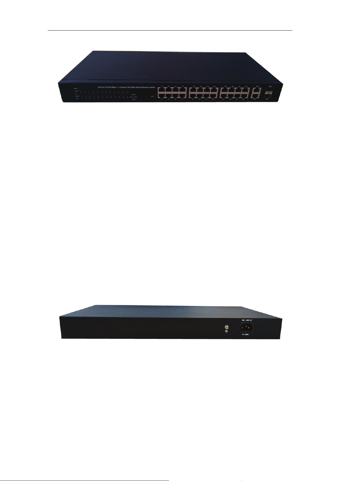
1.3.1 Front Panel
The front panel of the Switch consists of series of LED indicators, 24 10/100Mbps RJ-45
ports, 2 10/100/1000Mbps RJ-45 ports and 2 SFP ports a shown as below.
3
Page 5
DIGITUS POE Web Smart Ethernet Switch
Figure 1 - Front Panel
10/100Mbps RJ-45 ports (1~24):
Designed to connect to the device with a bandwidth of 10Mbps or 100Mbps. Each has a
corresponding 10/100Mbps LED.
10/100/1000Mbps RJ-45 ports (25T, 26T):
Designed to connect to the device with a bandwidth of 10Mbps, 100Mbps or 1000Mbps.
Each shares a corresponding LED with an associated SFP port.
SFP ports (25S, 26S):
Designed to install the SFP module. The Switch features two SFP transceiver slots that are
shared with two associated RJ45 ports. A SFP port and an associated RJ45 port are
referred to as “Combo” port, which means they cannot be used simultaneously, and only
SFP port work or only RJ45 port work at the same time.
Reset:
Keep the device powered on and push a paper clip into the hole. Press down the button for
about 2 seconds. The system restores the factory default settings.
1.3.2 Rear Panel
The rear panel of the Switch contains AC power connector shown as below.
Figure 2 - Rear Panel
AC Power Connector:
Power is supplied through an external AC power adapter. It s
60Hz.
Grounding Terminal:
The Switch already comes with Lightning Protection Mechanism. You can also ground
the Switch through the PE (Protecting Earth) cable of AC cord or with Ground Cable.
upports AC 100 ~ 240V, 50 /
4
Page 6
DIGITUS POE Web Smart Ethernet Switch
1.3.3 LED Indicator Specification
The LED indicators of the Switch contain one Power, 26 LINK/ACT, 24 PoE status and 2
Speed. The LED Indicators will allow you to monitor, diagnose and troubleshoot any
potential problem with the Switch, connection or attached devices.
Figure 3 - LED Indicators
The following chart shows the LED indicators of the Switch along with explanation of each
indicator.
LED COLOR STATUS STATUS DESCRIPTION
Power Green
LINK/ACT
(1~24)
25, 26T/S
POE Orange
Green
LINK/ACT
Green
Speed
Green
On Power On
Off Power Off
On A device is connected to the port
Off A device is disconnected to the port
Flashing Sending or receiving data
On A device is connected to the port
Off A device is disconnected to the port
Flashing Sending or receiving data
On A 1000Mbps device is connected to the port
Off A 10Mbps device is connected to the port
Flashing A 100Mbps device is connected to the port
On
Off
Flashing
A Powered Device is connected to the port,
which supply power successfully.
No Powered Device connected to the port, or
no power is supplied according to the power
limits of the port.
The POE power circuit may be in short or the
power current may be overloaded.
5
Page 7
DIGITUS POE Web Smart Ethernet Switch
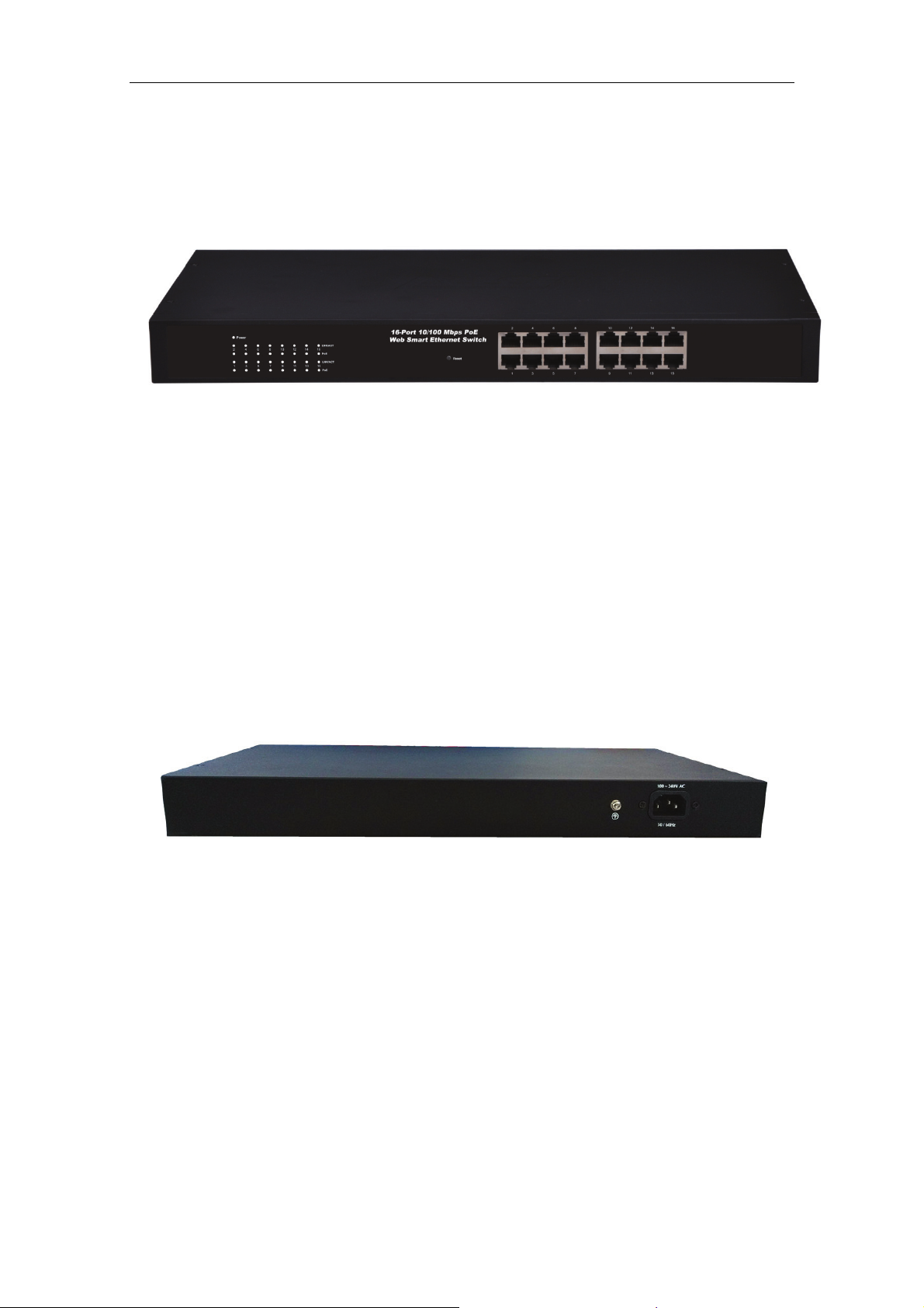
1.3.4 Front Panel
The front panel of the Switch consists of series of LED indicators and 16 10/100Mbps
RJ-45 ports.
Figure 1 - Front Panel
10/100Mbps RJ-45 ports (1~16):
Designed to connect to the device with a bandwidth of 10Mbps or 100Mbps. Each has a
corresponding 10/100Mbps LED.
Reset:
Keep the device powered on and push a paper clip into the hole. Press down the button for
about 2 seconds. The system restores the factory default settings.
1.3.5 Rear Panel
The rear panel of the Switch contains AC power connector shown as below.
Figure 2 - Rear Panel
AC Power Connector:
Power is supplied through an external AC power adapter. It supports
60Hz.
Grounding Terminal:
The Switch already comes with Lightning Protection Mechanism. You can also ground
the Switch through the PE (Protecting Earth) cable of AC cord or with Ground Cable.
AC 100 ~ 240V, 50 /
6
Page 8

DIGITUS POE Web Smart Ethernet Switch
1.3.6 LED Indicator Specification
The LED indicators of the Switch contain one Power, 26 LINK/ACT, 24 PoE status and 2
Speed. The LED Indicators will allow you to monitor, diagnose and troubleshoot any
potential problem with the Switch, connection or attached devices.
Figure 3 - LED Indicators
The following chart shows the LED indicators of the Switch along with explanation of each
indicator.
LED COLOR STATUS STATUS DESCRIPTION
Power Green
LINK/ACT
(1~16)
POE Orange
Green
On Power On
Off Power Off
On A device is connected to the port
Off A device is disconnected to the port
Flashing Sending or receiving data
On
Off
Flashing
A Powered Device is connected to the port,
which supply power successfully.
No Powered Device connected to the port, or
no power is supplied according to the power
limits of the port.
The POE power circuit may be in short or the
power current may be overloaded.
1.4 Environment
Operating Temperature: 0℃~40℃
Storage Temperature: -10℃~70℃
Operating Humidity: 10%~90% non-condensing
Storage humidity: 5%~90% non-condensing
1.5 Package Contents
One POE Web Smart Ethernet Switch
Four rubber feet, two mounting ears and eights screws
One AC power cord
One User Manual
7
Page 9
DIGITUS POE Web Smart Ethernet Switch
Chapter 2 Installing and Connecting the Switch
This part describes how to install your Ethernet Switch and make connections to it. Please
read the following topics and perform the procedures in the order being presented.
2.1 Installation
Please follow the following instructions in avoid of incorrect installation causing device
damage and security threat.
Put the Switch on stable place or desktop in case of falling damage.
Make sure the Switch works in the proper AC input range and matches the voltage
labeled on the Switch.
To keep the Switch free from lightning, do not open the Switch’s shell even in power
failure.
Make sure that there is proper heat dissipation from and adequate ventilation around
the Switch.
Make sure the cabinet to enough back up the weight of the Switch and its accessories.
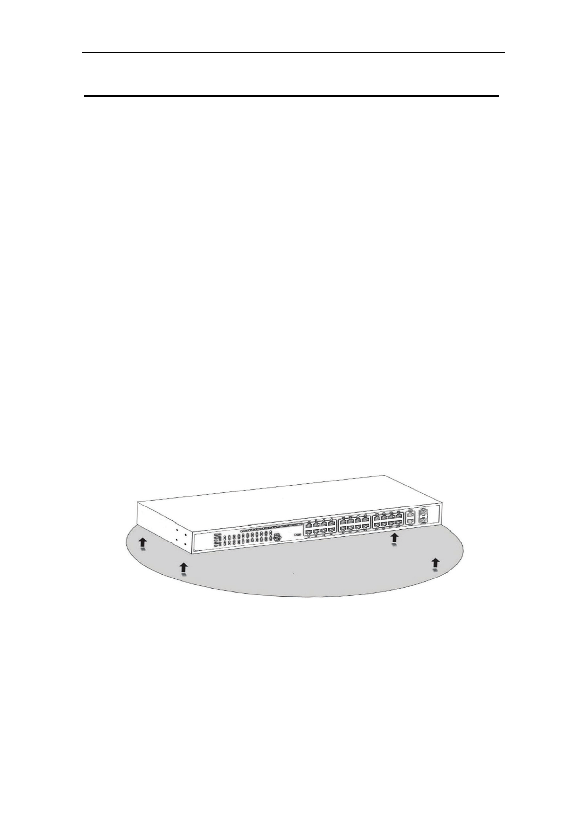
2.1.1 Desktop Installation
Sometimes users are not equipped with the 19-inch standard cabinet. So when installing the
Switch on a desktop, please attach these cushioning rubber feet provided on the bottom at
each corner of the Switch in case of the external vibration. Allow adequate space for
ventilation between the device and the objects around it.
Figure 4 - Desktop Installation
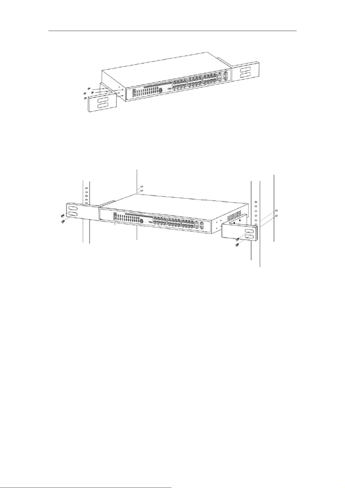
2.1.2 Rack-mountable Installation in 19-inch Cabinet
The Switch can be mounted in an EIA standard-sized, 19-inch rack, which can be placed in
a wiring closet with other equipment. To install the Switch, please follow these steps:
1.Attach the mounting brackets on the Switch’s side panels (one on each side) and secure
them with the screws provided.
8
Page 10
DIGITUS POE Web Smart Ethernet Switch
Figure 5 - Bracket Installation
2.Use the screws provided with the equipment rack to mount the Switch on the rack and
tighten it.
Figure 6 - Rack Installation
2.1.3 Power on the Switch
The Switch is powered on by the AC 100 ~ 240V 50 / 60Hz internal high-performance power
supply. Please follow the next tips to connect:
AC Electrical Outlet:
It is recommended to use single-phase three-wire receptacle with neutral outlet or
multifunctional computer professional receptacle. Please make sure to connect the metal
ground connector to the grounding source on the outlet.
AC Power Cord Connection:
Connect the AC power connector in the back panel of the Switch to external receptacle with
the included power cord, and check the power indicator is ON or not. When it is ON, it
indicates the power connection is OK.
9
Page 11

DIGITUS POE Web Smart Ethernet Switch
2.2 Connect Computer (NIC) to the Switch
Please insert the NIC into the computer, after installing network card driver, please connect
one end of the twisted pair to RJ-45 jack of your computer, the other end will be connected
to any RJ-45 port of the Switch, the distance between Switch and computer is around 100
meters. Once the connection is OK and the devices are power on normally, the LINK/ACT
status indicator lights corresponding ports of the Switch.
2.3 Switch connection to the PD
1-16/24 ports of the Switch have POE power supply function, the maximum output power up
to 30W each port, it can make PD devices, such as internet phone, network camera,
wireless access point work. You only need to connect the Switch POE port directly
connected to the PD port by network cable.
10
Page 12

DIGITUS POE Web Smart Ethernet Switch
Chapter 3 How to Login the Switch
3.1 Switch to End Node
Use standard Cat.5/5e Ethernet cable (UTP/STP) to connect the Switch to end nodes as
described below. Switch ports will automatically adjust to the characteristics (MDI/MDI-X,
speed, duplex) of the device to which is connected.
Please refer to the LED Indicator Specification. The LINK/ACT LEDs for each port lights
green when the link is available.
3.2 How to Login the Switch
As the Switch provides Web-based management login, you can configure your computer’s
IP address manually to log on to the Switch. The default settings of the Switch are shown
below.
Parameter Default Value
Default IP address 192.168.2.1
Default user name admin
Default password admin
You can log on to the configuration window of the Switch through following steps:
1. Connect the Switch with the computer NIC interface.
2. Power on the Switch.
3. Check whether the IP address of the computer is within this network segment:
192.168.2.xxx (“xxx” ranges 2~254), for example, 192.168.2.100.
4. Open the browser, and enter http://192.168.2.1 and then press “Enter”. The Switch
login window appears, as shown below.
11
Page 13

DIGITUS POE Web Smart Ethernet Switch
5. Enter the ID and Password (The factory default login ID is admin and Password is
admin), and then click “OK” to log in to the Switch configuration window as below.
(24-port version view)
In the Web GUI, the left column shows the configuration menu and the rest of the screen
area displays the configuration settings.
12
Page 14

DIGITUS POE Web Smart Ethernet Switch
Chapter 4 Switch Configuration
4.1 Administrator
4.1.1 Authentication configuration
Authentication Configuration diagram box allows user to modify Username and Password,
and then enter new username and password. After completing, press “Update” button to
take effect.
4.1.2 System IP Configuration
This page shows system configuration including the current IP Address and Subnet Mask,
Gateway, and IP Configure.
IP Address, Subnet Mask, and Gateway at system IP Configuration diagram box can be
configured by user. The Switch also supports DHCP methods to get IP address from DHCP
server.
4.1.3 System status
This page is used to check the status of the Switch, including the switch MAC address and
software version.
13
Page 15

DIGITUS POE Web Smart Ethernet Switch
The MAC address and version of the Switch will be shown at system status diagram box.
Comment field can accept "a-z", "A-Z", "0-9", "_", "+", "-", "=", excluding special character.
4.1.4 Load default setting
Clicking the "Load" button will make the switch being set to the original configuration.
When Load Default is executed, the all settings will be restored to default setting. Press
“Load” button at load default setting page, and then the process of the load default setting
will be executed. Press “Reboot” button to take effect.
After completing load default procedure, IP address, user name and password will keep
original setting.
4.1.5 Firmware update
After pressing “Update” button, the Switch will erase the older version flash code first. Then
enter file name at specific path, and the update will be completed.
Using default IP to execute firmware update process:
Enter password to execute firmware update process. After pressing “Update” button, the old
web code will be erased. After completing, select the image file and enter update button to
take effect.
14
Page 16

DIGITUS POE Web Smart Ethernet Switch
↓
↓
↓
↓
4.1.6 Reboot device
This page is used to reboot device.
Press “Confirm” button to take effect for rebooting device.
15
Page 17

DIGITUS POE Web Smart Ethernet Switch
4.2 POE
4.2.1 POE Status
This page is used to check POE Status, you can set Max Available Power here.
4.2.2 POE Setting
This page is for PoE setting.
Status: Enable or disable the specified function.
Priority: Setting the priority of POE.
16
Page 18

DIGITUS POE Web Smart Ethernet Switch
4.2.3 PoE Power Delay
This page is for setting PoE Power Delay.
4.2.4 PoE Scheduling
This page is for setting PoE Scheduling, it starts POE function at a specified time.
4.2.5 NTP Setting
This page is for NTP setting.
17
Page 19

DIGITUS POE Web Smart Ethernet Switch
NTP Server: This is the IP address of the NTP information will be taken from.
Time Zone: Select your local time zone from this pull down list.
4.3 Port Management
4.3.1 Port configuration
This page allows the user to configure operating mode of the physical port.
Tx/Rx Ability: Allow choosing all or one port of Switch for further management, the
available options is ALL & 01 to 16/24.
Auto-Negotiation: Enable and Disable. Being set as Auto, the speed and duplex mode are
negotiated automatically. When you set it as Disable, you have to set the speed and duplex
mode manually.
Speed: It is available for selecting hen the Negotiation column is set as Force. When the
Negotiation column is set as Auto, this column is read-only.
Duplex: It is available for selecting when the Negotiation column is set as Force. When the
Negotiation column is set as Auto, this column is read-only.
Pause: Flow Control for Full Duplex. When Flow Control is enabled, the switch can
synchronize the speed with its peer to avoid the packet loss caused by congestion.
18
Page 20

DIGITUS POE Web Smart Ethernet Switch
Backpressure: Flow Control for Half Duplex. A condition wherein a switch causes a
transmitting device to hold off on sending data packets until the switch bottleneck has been
eliminated.
Addr.Learning: Address learning is a service that characterizes a learning bridge, in which
the source MAC address of each received packet is stored so that future packets destined
for that address can be forwarded only to the bridge interface on which that address is
located.
After completing the settings, press “Update” button to take effect. The setting will be
reflected at current status window.
4.3.2 Port mirroring
The port mirroring function is accomplished by setting the following items.
(a) Destination port: Theoretically it’s possible to set more than one destination port in a
network. Actually the port mirroring function will lower the network throughput, and therefore
it’s recommended to set "only one" destination port in a network.
(b) Monitored packets: (1)Disable: means this function is disabled. (2)RX: means copy the
incoming packets of the selected source port to the selected destination port. (3)TX: means
copy the outgoing packets of the selected source port to the selected destination port. (4)Tx
& Rx: means the combination of Tx and Rx.
(c) Source port: The traffic source that will be copied to the destination port.
(24-port version view)
4.3.3 Bandwidth Control
This page allows the setting of the bandwidth for each port. The TX rate and Rx rate can be
filled with the number ranging 1 to 255. This number will be multiplied by the selected
bandwidth resolution and the result is the real bandwidth.
19
Page 21

DIGITUS POE Web Smart Ethernet Switch
4.3.4 Broadcast Storm Control
The broadcast storm control is used to block the excessive broadcast packets, the number
ranging from 1 to 63.
(2
4-port version view)
For example: The broadcast storm of the port1~8 are enabled and threshold is set to 10.
The broadcast packets will be dropped when broadcast packets are more than threshold
setting (packet length is 64 bytes).
(2
4-port version view)
4.4 VLAN Setting
4.4.1 VLAN mode
The Switch supports two VLAN modes, tag based and port based. When the port based
VLAN is selected, the tag setting will be useless. When the tag based VLAN is selected, the
user can define the handling method of a VLAN tag to the specified port, including "add a
20
Page 22

DIGITUS POE Web Smart Ethernet Switch
VLAN tag", " remove a VLAN tag" or "don’t care" about VLAN tag.
When click the "Change VLAN mode" button, the mode will change to Tag Base VLAN.
The egress packets of the output port will be added tag if add tag option is selected. The
egress packets of the output will be stripped tag if remove tag option is selected. Don’t care
means the egress packets of the output port only forward to destination without adding or
removing tag.
4.4.2 VLAN Member Setting
This page is used to set the VLAN ID. The VLAN ID is valid only when the tag based VLAN
is enabled. In port based VLAN mode, the VLAN ID is useless.
Port based VLAN
Port1~3 is set to same VLAN group and port4~8 is set to another VLAN group.
4-port version view)
(2
21
Page 23

DIGITUS POE Web Smart Ethernet Switch
Tag based VLAN
The following figure shows: 1, 2, 3, 4, 5, 6, 7 port in the same VLAN group. The 2 port tag
VID number is 123.
(2
4-port version view)
4.4.3 Multi-to-1 Setting
This setting is exclusive to VLAN setting on "VLAN member setting". When VLAN member
setting is updated, multi-to-1 setting will be void and vice versa. The "Disable Port" means
the port is excluded in this setting.
(2
4-port version view)
Note: If the VLAN mode changes from port base to tag base, the setting of the port base will
be cleared. Similarly, if the VLAN mode changes from tag base to port base, the setting of
the tag base will be cleared.
22
Page 24

DIGITUS POE Web Smart Ethernet Switch
In tag base mode, adding or removing tag doesn’t affect the source port connected with the
web.
4.5 Per Port Counter
This page provides port counter for each port. There are 4 groups of statistics in total.
(2
4-port version view)
4.6 QoS Setting
4.6.1 Priority mode
This page allows the user to set the scheduling mode for the TX packets priority. When the
queue weight is set to "0", it will be treated as "8".The "low weight" and "high weight" means
the ratio of the packet in the transmit queue. For example,If "low weight" and "high weight"
are set to "3" and "5", the ratio of the transmit packet for the low priority to high priority is 3/5.
23
Page 25

DIGITUS POE Web Smart Ethernet Switch
4.6.2 Port, 802.1p, IP/DS based
There are three COS types for this setting. The user can select more than one item for each
port.
As long as any of three CoS schemes(802.1p, IP TOS/DS or Port Base) is mapped to "high",
the data packet will be treated as the high priority.
4.6.3 TCP/UDP Port Based
This page allows the network administrator to assign the specific application to a priotity
queue. When the TCP/UDP port QoS function "override" item is selected, the Port_based,
Tag_based, IP TOS_based, CoS listed above will be ignored.
4.7 Security
4.7.1 MAC Address Binding
This is a port binding feature. This function provides a method for the administrator to
specify the relationship between the physical port and the MAC address. By specifying the
MAC address to each port, the switch can only forward the packets with source specified in
24
Page 26

DIGITUS POE Web Smart Ethernet Switch
the table. Each port can correspond to up to 3 MAC addresses.
4.7.2 TCP/UDP Filter
By selecting the TCP/UDP port, the user can optionally block some specific applications.
There are two kinds of protocol lists. The positive list makes the switch to forward the
selected protocol and drop other protocols. The negative list makes the switch drop the
selected protocol and forward other protocol. The protocol is checked at the selected secure
WAN port.
The Switch supports two methods to filter TCP/UDP protocol. Allow means that when the
port number of the selected port matches the port number of the filter setting, the packets
will be forwarded to destination port. Deny means that when the port number of the selected
port doesn’t match port number of the filter setting, the packets will be forwarded to
destination port.
25
Page 27

DIGITUS POE Web Smart Ethernet Switch
4.8 Spanning Tree
4.8.1 STP Bridge Settings
STP (Spanning Tree Protocol) is the acronym for spanning tree protocol, the protocol can be
applied to loop network, the algorithm by a certain path redundancy, while loop network
loop-free tree pruning into the network in order to avoid reporting Man in the loop network
hyperplasia and infinite loop. STP protocol will continue to 50s, this is the PC is turned on
and some 50s before they can access, for data transfer. RSTP STP improved algorithm,
within the agreement time to 1s.
4.8.2 STP Port Settings
This feature is available to you to switch the priority of each port and RPC set, usually set
according to the following priority rules, and RPC can remain the default.
RPC: Root Path Cost. The value range is 0 ~ 200000000, used to determine the port to the
root path cost, often with the speed, so when set to Auto, its value is inversely proportional to
speed.
Election root port, in accordance with the following principles. COST - Port ID, compare the
COST value, that is, the cost of the port to the root bridge. COST lower the value the more
the priority.
【COST VALUE】
Bandwidth COST
10Gps 2
1Gps 4
100M 19
10M 100
26
Page 28

DIGITUS POE Web Smart Ethernet Switch
4.8.3 Loopback Detection
The features available to you under the loop test set, the "Loopback Detect Function", set to
"Enable". When you produce the lower loop switch when the switch will automatically block
out the port connecting to ensure other ports work.
When you set the "Auto Wake Up" and "Wake-Up Time Interval" option, and the network
loop appears when the intervals, the switch port will wake up trying to loop until the fault
discharged.
Reset All Ports: This button provides a key to force you to reset the port function.
Status: Display the current status of all ports.
27
Page 29

DIGITUS POE Web Smart Ethernet Switch
(2
4-port version view)
4.9 Trunking
Port aggregation is to bring together multiple ports together to form a group to achieve entry
/ exit load in the aggregation group, all members of the port-sharing, while also providing a
higher connection reliability.
Note: According to LACP specifications, the same group for each Member port Trunk
connection speed and Duplex must be consistent, otherwise not work properly.
System Priority: Set the Switch System Priority, a value of 1 to 65535.
Link Aggregation Algorithm: MAC Src on behalf of Source MAC address. MAC Dst on
behalf of Destination MAC address.
28
Page 30

DIGITUS POE Web Smart Ethernet Switch
4.10 DHCP Relay Agent
4.10.1 DHCP Relay Agent
DHCP provides a transparent transmission to DHCP broadcast packet. It can transmitted
broadcast packet in one DHCP client(or server) to another segments of the DHCP server(or
client) transparently. Client in subnet can communicate with other subnet DHCP server
through DHCP Relay.
4.10.2 Relay Server
Set the DHCP server IP.
4.10.3 VLAN MAP Relay Agent
Enter the VLAN ID value within 1-4094.
4.11 Backup/Recovery
This function provides the user with a method to backup/recovery the switch configuration.
The user can save configuration file to specified path. If the user wants to recover the
original configuration, which is saved at the specified path, entering the password and then
pressing the "Update" button could recover the original configuration.
29
Page 31

DIGITUS POE Web Smart Ethernet Switch
The contents of the EEPROM can be saved to specific path, and the default name is
down.bin.
4.12 Miscellaneous
Miscellaneous is used to configure output queue aging time, VLAN stride, IGMP snooping,
and VLAN uplink function setting.
Output Queue Aging Time
This function is enabled for avoiding poor utilization of switch while pause packets is
received, The normal packets from transmitted port (port1) can be forwarded to other port if
port2 continues to assert pause frame.
30
Page 32

DIGITUS POE Web Smart Ethernet Switch
VLAN Striding
By selecting this function, switch will forward unicast packets to destination port, no matter
whether destination port is in the same VLAN.
IGMP Snooping V1 & V2
This function is enabled for supporting IGMPv1, IPMPv2 protocol to create IGMP group.
Uplink port
This function allows different VLAN use their individual uplink port to forward packets. In a
normal application, "only one" uplink port can be selected in a switch.
4.13 SNMP Settings
SNMP(Simple Network Management Protocol), used to manage the communication line.
You can Enable or Disable SNMP Settings here.
4.14 Logout
Press “Logout” button to logout web page.
→
31
Page 33

DIGITUS POE Web Smart Ethernet Switch
s
Appendix: Technical Specifications
Model
DN-95312 DN-95313
Number of Ports
10/100M
LED Indicator
PoE Power
Transfer Method Store-and-Forward
Switching Capacity
MAC Address Learning Automatically learning, automatically Update 4K
Standards IEEE802.3 10Base-T, IEEE802.3u 100Base-TX, IEEE802.3af, IEEE802.3at
Network Media (RJ-45)
Dimensions (L × W × H) 440*208*44 mm
Environment
AC Input AC: 100V~240V 50/60HZ
Power consumption
POE
Power
16 x 10/100Mbps Auto-Negotiation ports
Link/Act
Power
Power-: pin 4 & pin 5 Power+: pin 4 & pin 5
Power+: pin 7 & pin 8 Power -: pin 7 & pin 8
3.2G 8.8G
10BASE-T: UTP category 5 cable (maximum 100m)
100BASE-T: UTP category 5,5e cable (maximum 100m)
Operating Temperature: 0℃~40
Operating Humidity: 10%~90% non-condensing
Storage Temperature: -10℃~70
Storage humidity: 5%~90% non-condensing
260 W
24 x 10/100Mbps Auto-Negotiation
ports,2 x 1000Mbps Combo
PoE
1000Base-T: UTP category 5e, 6
cable (maximum 100m)
℃
℃
330 W
32
 Loading...