

Page 1
2SFP Port 10/100/1000Mbps
Web Smart Ethernet Switch
DN-80201
DN-80211-1
DN-80221-1
Manual
DN-80201 DN-80211-1 DN-80221-1
1
Page 2

Table of Contents
Chapter 1 Product Introduction ..................................................................................... 4
1.1 Product Overview ................................................................................................. 4
1.2 Features (8 port )………………………………………………………………………..4
1.2.1 Features ( 16 port )………….……………………………………………….……….5
1.2.2 Features ( 24 port )……………………………………………………………………5
1.3 External Component Description (8 port)…………………………………………….6
1.3.1 Front Panel (8 port)……………………………………………………………...6
1.3.2 Rear Panel (8 port)………………………………………………………………7
1.3.3 External Component Description (16 port)……………………………………..….8
1.3.4 Front Panel (16 port)………………………………………………………………….8
1.3.5 Rear Panel (16 port)………………………………………………………………….9
1.3.6 External Component Description (24 port)………………………………………..10
1.3.7 Front Panel (24 port)………………………………………………………………...10
1.3.8 Rear Panel (24 port)…………………………………………………………………11
1.4 Package Contents ( 8 port )…………………………………………………………..12
1.4.1 Package Contents ( 16 port )……………………………………………………….12
1.4.2 Package Contents ( 24 port )……………………………………………………….12
Chapter 2 Installing and Connecting the Switch…………………………………………13
2.1 Installation………………………………………………………………………………13
2.1.1 Desktop Installation ( 8 port )………………………………………………….13
2.1.2 Rack-mountable Installation in 19-inch Cabinet ( 8 port )…….……………13
2.1.3 Power on the Switch ( 8 port )………………………………………………..14
2.1.4 Desktop Installation ( 16 port )………………………………………………..14
2.1.5 Rack-mountable Installation in 19-inch Cabinet ( 16 port )………………..15
2.1.6 Power on the Switch ( 16 port )……………………………………………….16
2.1.7 Desktop Installation ( 24 port )………………………………………………..16
2.1.8 Rack-mountable Installation in 19-inch Cabinet ( 24 port )………………..17
2.1.9 Power on the Switch ( 24 port )……………………………………………….18
2.2 Connect Computer (NIC) to the Switch .............................................................. 18
Chapter 3 How to Login the Switch ( 8 port )……………………………………………..18
3.1 Switch to End Node ( 8 port )…………………………………………………………18
3.2 How to Login the Switch ( 8 port )……………………………………………………19
Chapter 3 How to Login the Switch ( 16 port )…………………………………………….21
3.3 Switch to End Node ( 16 port )………………………………………………………..21
3.4 How to Login the Switch ( 16 port )…………………………………………………..21
Chapter 3 How to Login the Switch ( 24 port )…………………………………………….23
3.5 Switch to End Node ( 24 port )………………………………………………………..23
3.6 How to Login the Switch ( 24 port )…………………………………………………..23
Chapter 4 Switch Configuration …………………………………………………………….25
4.1 Status ................................................................................................................. 25
4.1.1 System Information .................................................................................. 25
2
Page 3

4.1.2 Logging Message .................................................................................... 26
4.1.3 Port .......................................................................................................... 26
4.1.4 Link Aggregation ...................................................................................... 28
4.1.5 LLDP Statistics ......................................................................................... 28
4.1.6 IGMP Snooping Statistics ........................................................................ 29
4.2 Network .............................................................................................................. 30
4.2.1 IP Address ............................................................................................... 30
4.2.2 Time Settings ........................................................................................... 30
4.3 Switching ............................................................................................................ 31
4.3.1 Port Setting .............................................................................................. 31
4.3.2 Error Disabled .......................................................................................... 32
4.3.3 Mirror ....................................................................................................... 33
4.3.4 Link Aggregation ...................................................................................... 33
4.3.5 Vlan Management .................................................................................... 36
4.3.6 Multicast ................................................................................................. 39
4.3.7 Jum bo Frame .......................................................................................... 44
4.3.8 STP .......................................................................................................... 45
4.4 Mac Address Table ............................................................................................. 48
4.4.1 Static Mac Setting .................................................................................... 48
4.4.2 MAC Filtering ........................................................................................... 49
4.4.3 Dynamic Address Setting ......................................................................... 49
4.4.4 Dynamic Learned ..................................................................................... 50
4.4.5 RMA MAC Address .................................................................................. 50
4.5 Security .............................................................................................................. 50
4.5.1 Storm Control ........................................................................................... 50
4.5.2 802.1X ..................................................................................................... 51
4.5.3 DHCP Snooping ....................................................................................... 53
4.5.4 Port Security ............................................................................................ 57
4.5.5 AAA .......................................................................................................... 58
4.5.6 Tacacs+ Server ........................................................................................ 61
4.5.7 Radius server ........................................................................................... 61
4.5.8 Access ..................................................................................................... 62
4.6 ACL .................................................................................................................... 65
4.6.1 MAC-Based ACL ...................................................................................... 65
4.6.2 MAC-Based ACE ..................................................................................... 65
4.6.3 IPv4-Based ACL ...................................................................................... 65
4.6.4 IPv4-Based ACE ...................................................................................... 66
4.6.5 ACL Binding ............................................................................................. 66
4.7 QoS .................................................................................................................... 67
4.7.1 General .................................................................................................... 67
4.7.2 QoS Basic Mode ...................................................................................... 69
4.7.3 QoS Advanced Mode ............................................................................... 70
4.7.4 Rate Limit ................................................................................................. 73
4.8 Management ...................................................................................................... 74
3
Page 4

4.8.1 LLDP ........................................................................................................ 74
4.8.2 SNMP ...................................................................................................... 78
4.8.3 RMON ...................................................................................................... 82
4.9 Diagnostics ........................................................................................................ 84
4.9.1 System Status .......................................................................................... 84
4.9.2 Ping Test .................................................................................................. 84
4.9.3 Logging Setting ........................................................................................ 85
4.9.4 Factory Default ........................................................................................ 86
4.9.5 Reboot Switch .......................................................................................... 86
4.10 Maintenance .................................................................................................... 87
4.10.1 Backup Manager .................................................................................... 87
4.10.2 Upgrade Manager .................................................................................. 88
4.10.3 Configuration Manager .......................................................................... 88
4.10.4 Account Manager ................................................................................... 89
4.10.5 Enable Password ................................................................................... 90
4
Page 5

Chapter 1 Product Introduction
Congratulations on purchasing of the Web Smart Ethernet Switch. Before you install and
use this product, please read this manual carefully for full exploiting the functions of this
product.
1.1 Product Overview
The 8/16/24 port + 2SFP 10/100/1000Mbps Managed Ethernet Switch provides seamless
network connection. It integrates 10/100/1000Mbps Ethernet network capabilities, and
can be configured by web based interface. Including administrator, port management,
VLAN setting, port statistics, trunking, QoS setting, security filter, configuration/
backup/recovery, log out, and so on.
1.2 Features (8 port )
Complies with IEEE802.3, IEEE 802.3u, IEEE 802.3ab standards
8 x 10/100/1000Mbps Auto-Negotiation RJ45 ports supporting Auto-MDI/MDIX
Support Console port management
Supports IEEE802.3x flow control for Full-duplex Mode and back pressure for
Half-duplex Mode
8K entry MAC address table with auto-learning and auto-aging
Supports WEB management interface
LED indicators for monitoring power, link, activity and speed
5
Page 6

1.2.1 Features (16 port)
Comply with IEEE802.3, IEEE802.3u, IEEE802.3ab, IEEE802.3x, IEEE802.3z,
EEE802.3ad standards
Supports IEEE802.3x flow control for Full-duplex Mode and back pressure for
Half-duplex Mode
Supports MAC address auto-learning and auto-aging
Store and forward mode operates
Support SNMP/RMON/TELENT
Supports IEEE802.1Q VLAN,4K VLAN Table
Support IEEE802.1p Priority Queues
Support ACL Function, 1.5K-entry ALC table
Support Storm Control
Support QoS, Port Mirroring, Link Aggregation Protocol
LED indicators for monitoring power, link/activity
Web-based Management Support
Internal power adapter supply
1.2.2 Features (24 port)
Comply with IEEE802.3, IEEE802.3u, IEEE802.3ab, IEEE802.3x, IEEE802.3z,
EEE802.3ad standards
Supports IEEE802.3x flow control for Full-duplex Mode and back pressure for
Half-duplex Mode
Supports MAC address auto-learning and auto-aging
Store and forward mode operates
Support SNMP/RMON/TELENT
Supports IEEE802.1Q VLAN,4K VLAN Table
Support IEEE802.1p Priority Queues
Support ACL Function, 1.5K-entry ALC table
Support Storm Control
Support QoS, Port Mirroring, Link Aggregation Protocol
LED indicators for monitoring power, link/activity
Web-based Management Support
Internal power adapter supply
6
Page 7
1.3 External Component Description (8 port)
1.3.1 Front Panel (8 port)
The front panel of the Switch consists of 8 x 10/100/1000Mbps RJ-45 ports, 2 x SFP
ports, 1 x Console port, 1 x Reset button and a series of LED indicators as shown as
below.
Figure 1 - Front Panel
10/100/1000Mbps RJ-45 ports (1~8):
Designed to connect to devices with a bandwidth of 10Mbps, 100Mbps or 1000Mbps.
Each has a corresponding 10/100/1000Mbps LED.
SFP ports (SFP1, SFP2):
Designed to install SFP module and connect to devices with a bandwidth of 1000Mbps.
Each has a corresponding 1000Mbps LED.
Console port (Console):
Designed to connect with serial port of a computer or terminal for monitoring and
configuring the Switch.
Reset button (Reset):
Keep the device powered on and press down the button for about 5 seconds. The
system restores the factory default settings.
LED indicators:
The LED Indicators will allow you to monitor, diagnose and troubleshoot any potential
problem with the Switch, connection or attached devices.
7
Page 8
Figure 2 - LED Indicators
The following chart shows the LED indicators of the Switch along with explanation of each
indicator.
LED COLOR STATUS STATUS DESCRIPTION
On Power On
Power Green
Off Power Off
On A device is connected to the port
Off No device is connected to the port
Flashing Sending or receiving data
On A device is connected to the port
Off No device is connected to the port
Flashing Sending or receiving data
LNK/ACT/
Speed
(1~8)
SFP1
SFP2
10/100Mbps:
Orange
1000Mbps:
Green
Green
1.3.2 Rear Panel (8 port)
The rear panel of the Switch contains AC power connector shown as below.
Figure 3 - Rear Panel
AC Power Connector:
Power is supplied through an external AC power adapter. It
50~60Hz.
8
supports AC 100~240V,
Page 9
1.3.3 External Component Description (16 port)
1.3.4 Front Panel (16 port)
The front panel of the Switch consists of 16 x 10/100/1000Mbps RJ-45 ports, 2 x SFP
ports, 1 x Console port, 1 x Reset button and a series of LED indicators as shown as
below.
Figure 1 - Front Panel
10/100/1000Mbps RJ-45 ports (1~16):
Design to connect to the device with a bandwidth of 10Mbps, 100Mbps or 1000Mbps.
Each has a corresponding 10/100/1000Mbps LED.
SFP ports (SFP1, SFP2):
Design to install the SFP module and connect to the device with a bandwidth of 1000Mbps.
Each has a corresponding 1000Mbps LED.
Console port (Console):
Design to connect with the serial port of a computer or terminal for monitoring and
configuring the Switch.
Reset button (Reset):
Keep the device powered on and press down the button for about 5 seconds. The system
restores the factory default settings.
LED indicators:
The LED Indicators will allow you to monitor, diagnose and troubleshoot any potential
problem with the Switch, connection or attached devices.
Figure 2 - LED Indicators
9
Page 10
The following chart shows the LED indicators of the Switch along with explanation of each
indicator.
LED COLOR STATUS STATUS DESCRIPTION
On Power On
Power Red
Off Power Off
On A device is connected to the port
Off No device is connected to the port
Flashing Sending or receiving data
On A device is connected to the port
Off No device is connected to the port
Flashing Sending or receiving data
LNK/ACT/
Speed
(1~16)
SFP1
SFP2
10/100Mbps:
Orange
1000Mbps:
Green
Green
1.3.5 Rear Panel (16 port)
The rear panel of the Switch contains AC power connector shown as below.
Figure 3 - Rear Panel
AC Power Connector:
Power is supplied through an external AC power adapter. It
50~60Hz.
Grounding Terminal:
The Switch already comes with Lightning Protection Mechanism. You can also ground
the Switch through the PE (Protecting Earth) cable of AC cord or with Ground Cable.
supports AC 100~240V,
10
Page 11
1.3.6 External Component Description (24 port)
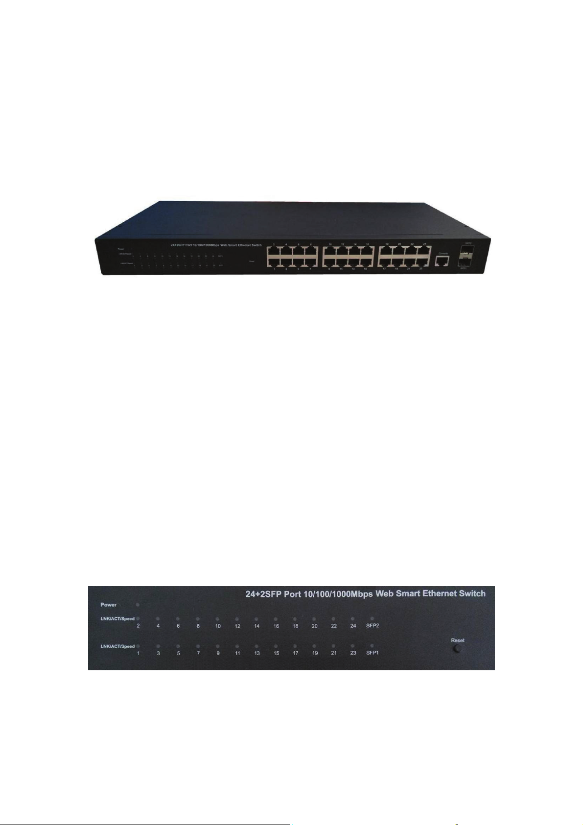
1.3.7 Front Panel (24 port)
The front panel of the Switch consists of 24 x 10/100/1000Mbps RJ-45 ports,2 x SFP
ports,1 x Console port, 1 x Reset button and a series of LED indicators as shown as
below.
Figure 1 - Front Panel
10/100/1000Mbps RJ-45 ports (1~24):
Design to connect to the device with a bandwidth of 10Mbps, 100Mbps or 1000Mbps.
Each has a corresponding 10/100/1000Mbps LED.
SFP ports (SFP1, SFP2):
Design to install the SFP module and connect to the device with a bandwidth of 1000Mbps.
Each has a corresponding 1000Mbps LED.
Console port (Console):
Design to connect with the serial port of a computer or terminal for monitoring and
configuring the Switch.
Reset button (Reset):
Keep the device powered on and press down the button for about 5 seconds. The system
restores the factory default settings.
LED indicators:
The LED Indicators will allow you to monitor, diagnose and troubleshoot any potential
problem with the Switch, connection or attached devices.
Figure 2 - LED Indicators
11
Page 12
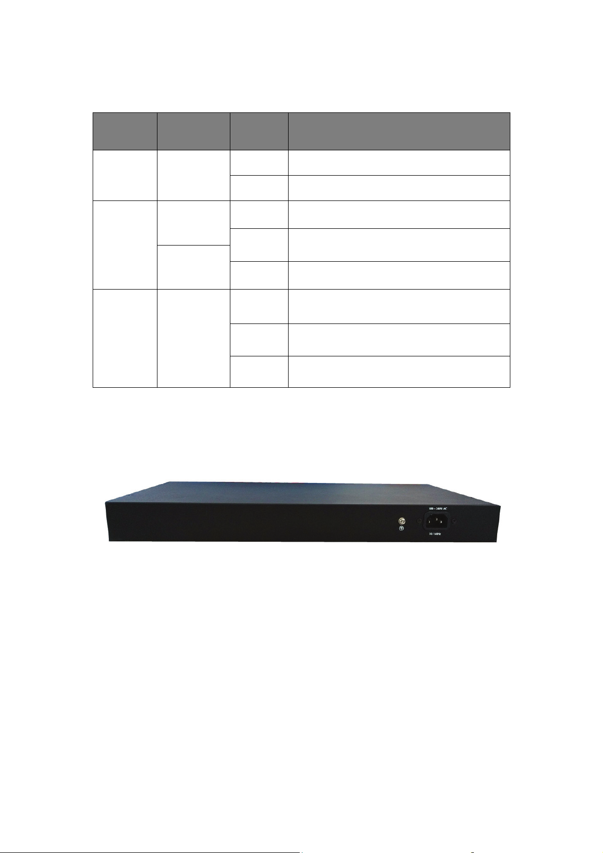
The following chart shows the LED indicators of the Switch along with explanation of each
indicator.
LED COLOR STATUS STATUS DESCRIPTION
On Power On
Power Red
Off Power Off
On A device is connected to the port
Off A device is disconnected to the port
Flashing Sending or receiving data
On A device is connected to the port
Off A device is disconnected to the port
Flashing Sending or receiving data
LNK/ACT/
Speed
(1~24)
SFP1
SFP2
10/100Mbps:
Orange
1000Mbps:
Green
Green
1.3.8 Rear Panel (24 port)
The rear panel of the Switch contains AC power connector and one marker shown as
below.
Figure 3 - Rear Panel
AC Power Connector:
Power is supplied through an external AC power adapter. It
50~60Hz.
Grounding Terminal:
The Switch already comes with Lightning Protection Mechanism. You can also ground
the Switch through the PE (Protecting Earth) cable of AC cord or with Ground Cable.
supports AC 100~240V,
1.4 Package Contents (8 port)
Before installing the Switch, make sure that the following "packing list" listed OK. If any
12
Page 13

part is lost and damaged, please contact your local agent immediately. In addition, make
sure that you have the tools install switches and cables by your hands.
One Web Smart Ethernet Switch
Four rubber feet, two mounting ears and eights screws
One AC power cord
One User Manual
1.4.1 Package Contents (16 port)
Before installing the Switch, make sure that the following the "packing list" listed OK. If any
part is lost and damaged, please contact your local agent immediately. In addition, make
sure that you have the tools install switches and cables by your hands.
One Web Smart Ethernet Switch
Four rubber feet, two mounting ears and eights screws
One AC power cord
One User Manual
1.4.2 Package Contents (24 port)
Before installing the Switch, make sure that the following the "packing list" listed OK. If any
part is lost and damaged, please contact your local agent immediately. In addition, make
sure that you have the tools install switches and cables by your hands.
One Web Smart Ethernet Switch
Four rubber feet, two mounting ears and eights screws
One AC power cord
One User Manual
13
Page 14

Chapter 2 Installing and Connecting the Switch
This part describes how to install your Web Smart Ethernet Switch and make connections
to it. Please read the following topics and perform the procedures in the order being
presented.
2.1 Installation
Please follow the following instructions in avoid of incorrect installation causing device
damage and security threat.
Put the Switch on stable place or desktop in case of falling damage.
Make sure the Switch works in the proper AC input range and matches the voltage
labeled on the Switch.
To keep the Switch free from lightning, do not open the Switch’s shell even in power
failure.
Make sure that there is proper heat dissipation from and adequate ventilation around
the Switch.
Make sure that the cabinet has enough back up for the weight of the Switch and its
accessories.
2.1.1 Desktop Installation (8 port)
Sometimes users are not equipped with the 19-inch standard cabinet. So when installing
the Switch on a desktop, please attach these cushioning rubber feet provided on the
bottom at each corner of the Switch in case of the external vibration. Allow adequate
space for ventilation between the device and the objects around it.
2.1.2 Rack-mountable Installation in 19-inch Cabinet ( 8 port )
The Switch can be mounted in an EIA standard-sized, 19-inch rack, which can be placed
in a wiring closet with other equipment. To install the Switch, please follow these steps:
a. Attach the mounting brackets on the Switch’s side panels (one on each side) and
secure them with the screws provided.
Figure 4 - Bracket Installation
14
Page 15

b. Use the screws provided with the equipment rack to mount the Switch on the rack
and tighten it.
Figure 5 - Rack Installation
2.1.3 Power on the Switch (8 port)
The Switch is powered by AC 100-240V 50/60Hz internal high-performance power supply.
Please follow the next tips to connect:
AC Electrical Outlet:
It is recommended to use single-phase three-wire receptacle with neutral outlet or
multifunctional computer professional receptacle. Please make sure to connect the metal
ground connector to the grounding source on the outlet.
AC Power Cord Connection:
Connect the AC power connector in the back panel of the Switch to external receptacle
with the included power cord, and check the power indicator is ON or not. When it is ON, it
indicates the power connection is OK.
2.1.4 Desktop Installation (16 port)
Sometimes users are not equipped with the 19-inch standard cabinet. So when installing
the Switch on a desktop, please attach these cushioning rubber feet provided on the
bottom at each corner of the Switch in case of the external vibration. Allow adequate
space for ventilation between the device and the objects around it.
15
Page 16
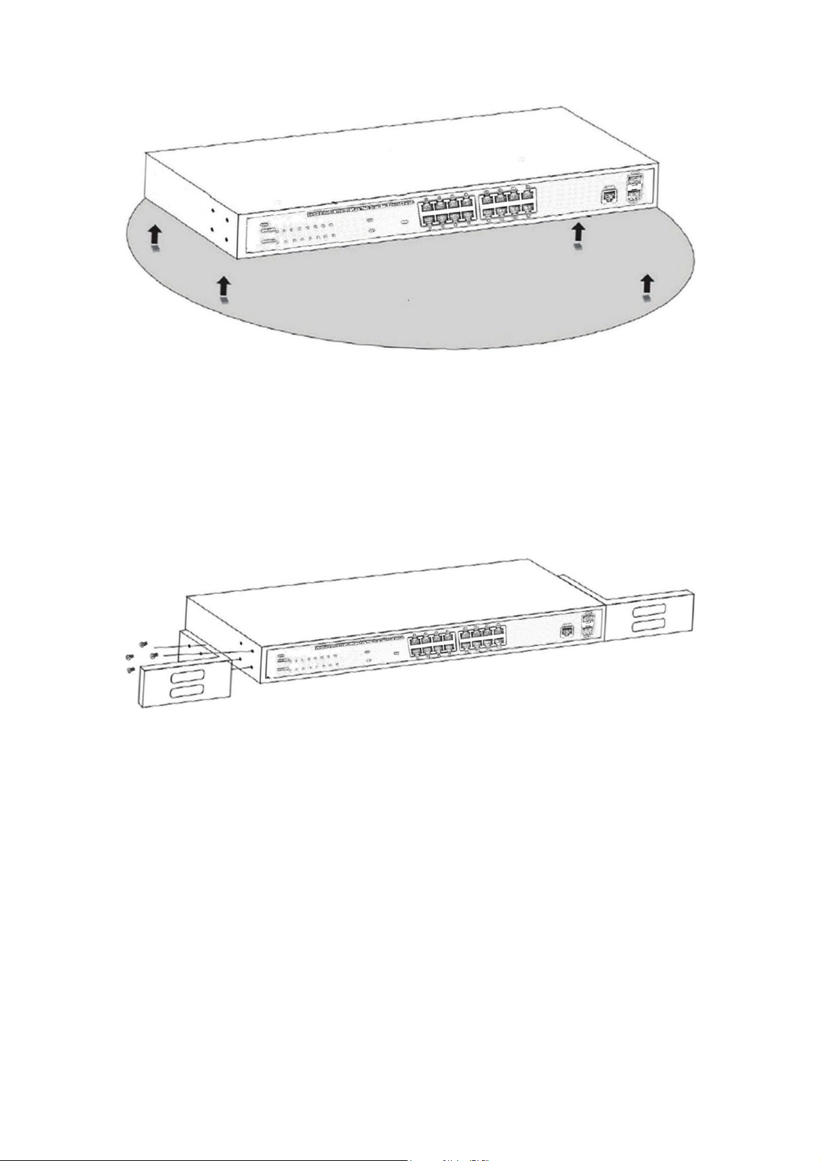
Figure 4 - Desktop Installation
2.1.5 Rack-mountable Installation in 19-inch Cabinet (16 port)
The Switch can be mounted in an EIA standard-sized, 19-inch rack, which can be placed
in a wiring closet with other equipment. To install the Switch, please follow these steps:
c. Attach the mounting brackets on the Switch’s side panels (one on each side) and
secure them with the screws provided.
Figure 5 - Bracket Installation
d. Use the screws provided with the equipment rack to mount the Switch on the rack
and tighten it.
16
Page 17

Figure 6 - Rack Installation
2.1.6 Power on the Switch (16 port)
The Switch is powered on by the AC 100-240V 50/60Hz internal high-performance power
supply. Please follow the next tips to connect:
AC Electrical Outlet:
It is recommended to use single-phase three-wire receptacle with neutral outlet or
multifunctional computer professional receptacle. Please make sure to connect the metal
ground connector to the grounding source on the outlet.
AC Power Cord Connection:
Connect the AC power connector in the back panel of the Switch to external receptacle
with the included power cord, and check the power indicator is ON or not. When it is ON, it
indicates the power connection is OK.
2.1.7 Desktop Installation (24 port)
Sometimes users are not equipped with the 19-inch standard cabinet. So when installing
the Switch on a desktop, please attach these cushioning rubber feet provided on the
bottom at each corner of the Switch in case of the external vibration. Allow adequate
space for ventilation between the device and the objects around it.
17
Page 18
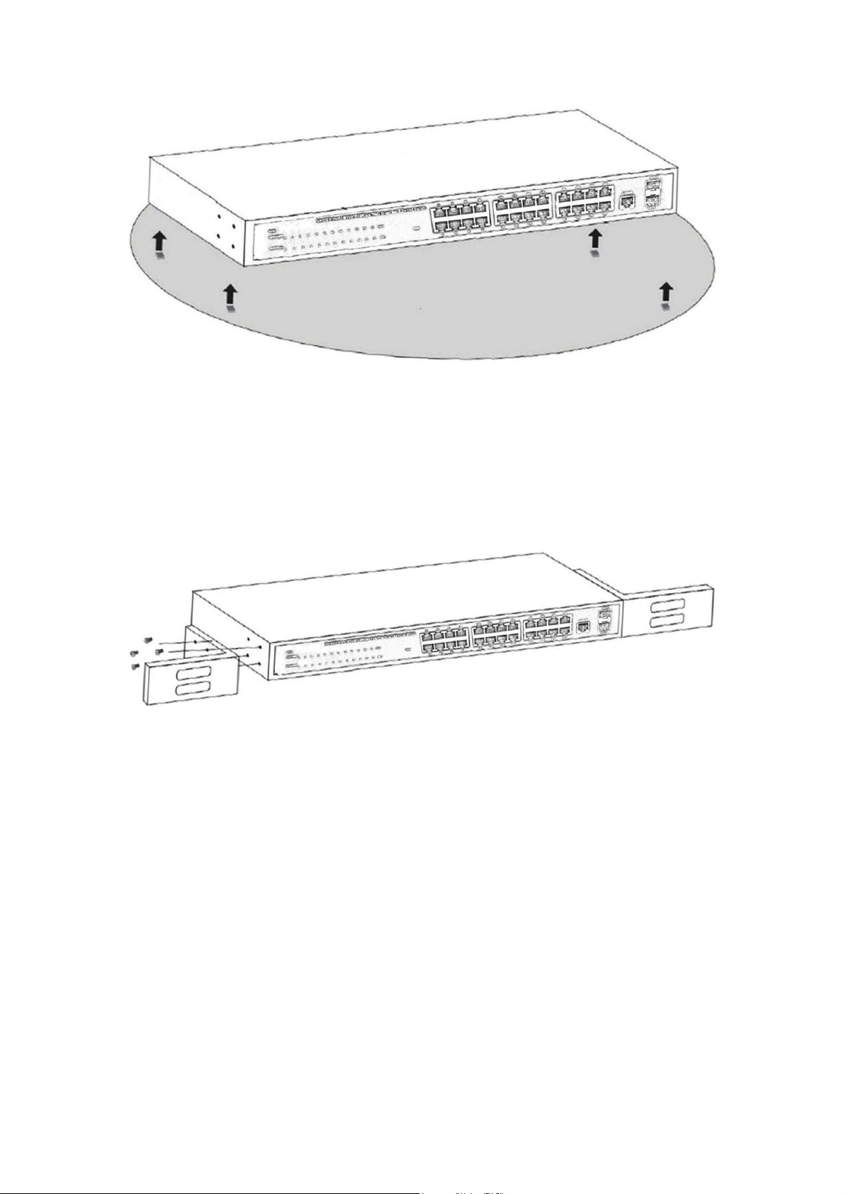
Figure 4 - Desktop Installation
2.1.8 Rack-mountable Installation in 19-inch Cabinet (24 port)
The Switch can be mounted in an EIA standard-sized, 19-inch rack, which can be placed
in a wiring closet with other equipment. To install the Switch, please follow these steps:
e. Attach the mounting brackets on the Switch’s side panels (one on each side) and
secure them with the screws provided.
Figure 5 - Bracket Installation
18
Page 19
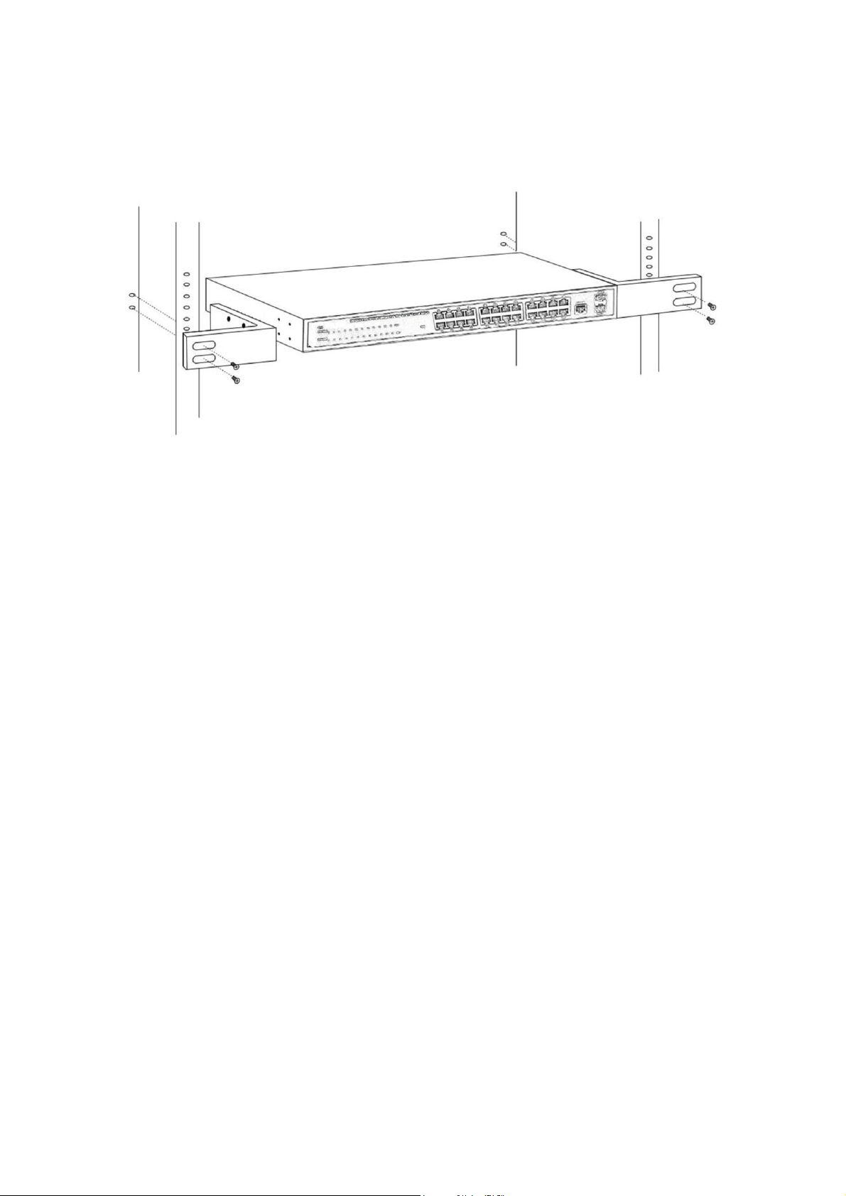
f. Use the screws provided with the equipment rack to mount the Switch on the rack
and tighten it.
Figure 6 - Rack Installation
2.1.9 Power on the Switch (24 port)
The Switch is powered on by the AC 100-240V 50/60Hz internal high-performance power
supply. Please follow the next tips to connect:
AC Electrical Outlet:
It is recommended to use single-phase three-wire receptacle with neutral outlet or
multifunctional computer professional receptacle. Please make sure to connect the metal
ground connector to the grounding source on the outlet.
AC Power Cord Connection:
Connect the AC power connector in the back panel of the Switch to external receptacle
with the included power cord, and check the power indicator is ON or not. When it is ON, it
indicates the power connection is OK.
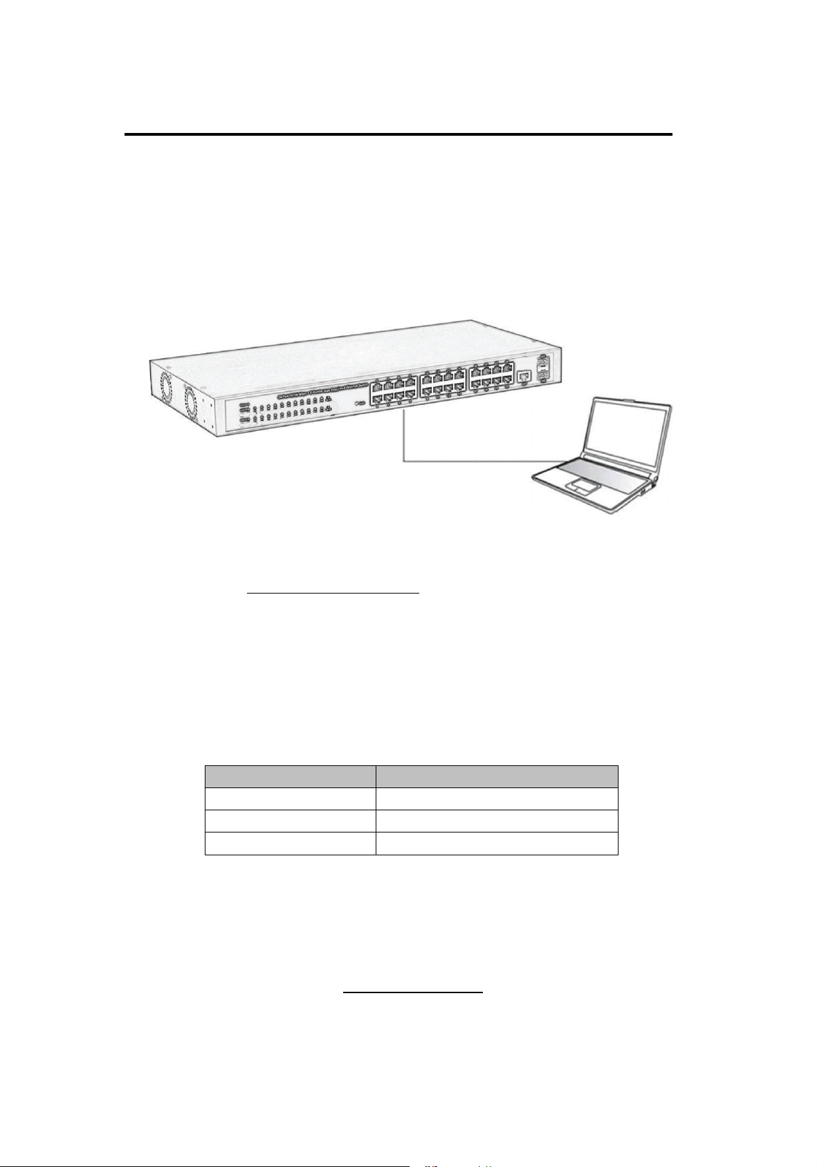
2.2 Connect Computer (NIC) to the Switch
Please insert the NIC into the computer, after installing network card driver, please
connect one end of the twisted pair to RJ-45 jack of your computer, the other end will be
connected to any RJ-45 port of the Switch, the distance between Switch and computer is
around 100 meters. Once the connection is OK and the devices are power on normally,
the LINK/ACT/Speed status indicator lights corresponding ports of the Switch.
19
Page 20
Chapter 3 How to Login the Switch (8 port)
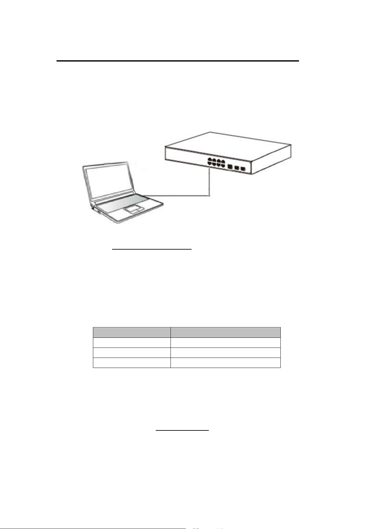
3.1 Switch to End Node (8 port)
Use standard Cat.5/5e Ethernet cable (UTP/STP) to connect the Switch to end nodes as
described below. Switch ports will automatically adjust to the characteristics (MDI/MDI-X,
speed, duplex) of the device to which is connected.
Figure 6 - PC Connect
Please refer to the LED Indicator Specification. The LINK/ACT/Speed LEDs for each port
lights on when the link is available.
3.2 How to Login the Switch (8 port)
As the Switch provides Web-based management login, you can configure your computer’s
IP address manually to log on to the Switch. The default settings of the Switch are shown
below.
Parameter Default Value
Default IP address 192.168.2.1
Default user name admin
Default password admin
You can log on to the configuration window of the Switch through following steps:
1. Connect the Switch with the computer NIC interface.
2. Power on the Switch.
3. Check whether the IP address of the computer is within this network segment:
192.168.2.xxx (“xxx” ranges 2~254), for example, 192.168.2.100.
4. Open the browser, and enter http://192.168.2.1 and then press “Enter”. The Switch
login window appears, as shown below.
20
Page 21

Figure 7 - Login Window
5. Enter the Username and Password (The factory default Username is admin and
Password is admin), and then click “LOGIN” to log in to the Switch configuration window
as below.
Figure 8 - Configuration Window
21
Page 22
Chapter 3 How to Login the Switch (16 port)
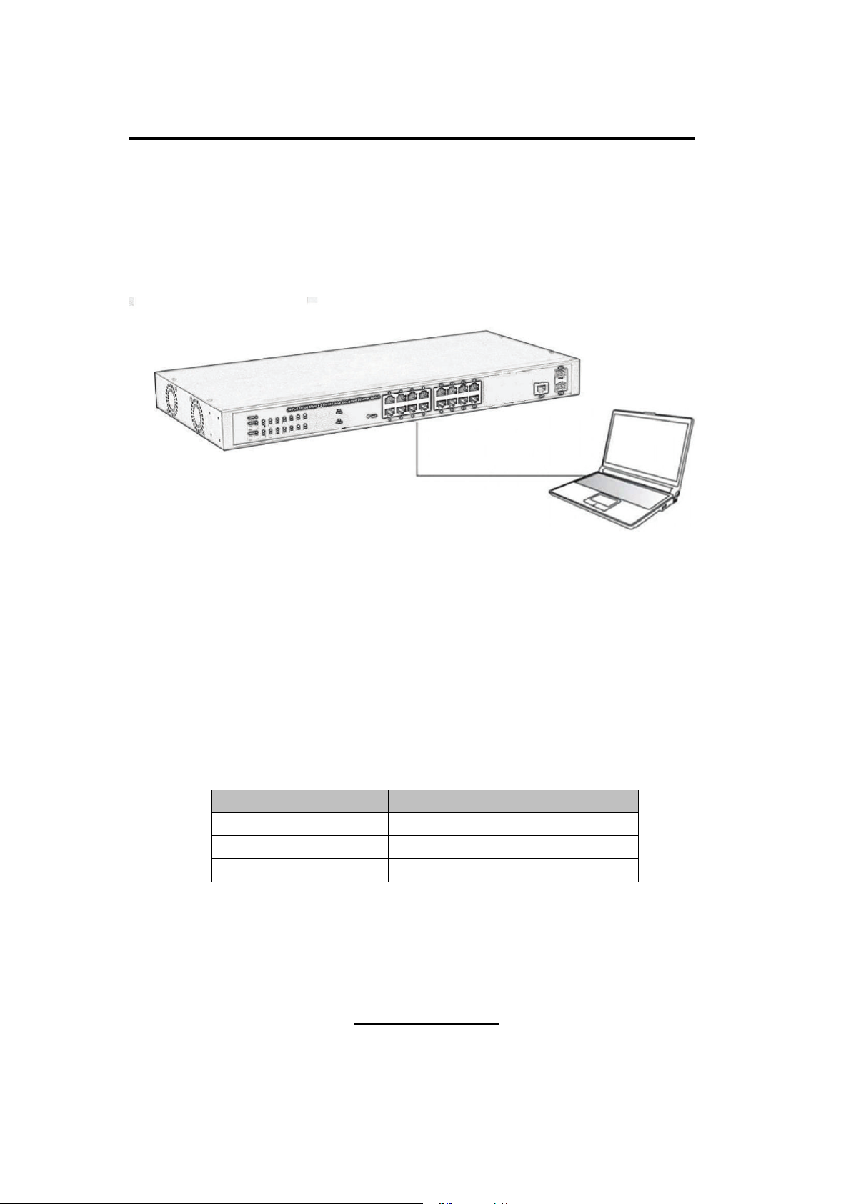
3.3 Switch to End Node (16 port)
Use standard Cat.5/5e Ethernet cable (UTP/STP) to connect the Switch to end nodes as
described below. Switch ports will automatically adjust to the characteristics (MDI/MDI-X,
speed, duplex) of the device to which is connected.
Figure 7 - PC Connect
Please refer to the LED Indicator Specification.The LINK/ACT/Speed LEDs for each port
lights on when the link is available.
3.4 How to Login the Switch (16 port)
As the Switch provides Web-based management login, you can configure your computer’s
IP address manually to log on to the Switch. The default settings of the Switch are shown
below.
Parameter Default Value
Default IP address 192.168.2.1
Default user name admin
Default password admin
You can log on to the configuration window of the Switch through following steps:
6. Connect the Switch with the computer NIC interface.
7. Power on the Switch.
8. Check whether the IP address of the computer is within this network segment:
192.168.2.xxx (“xxx” ranges 2~254), for example, 192.168.2.100.
9. Open the browser, and enter
Switch login window appears, as shown below.
http://192.168.2.1
and then press “Enter”. The
22
Page 23
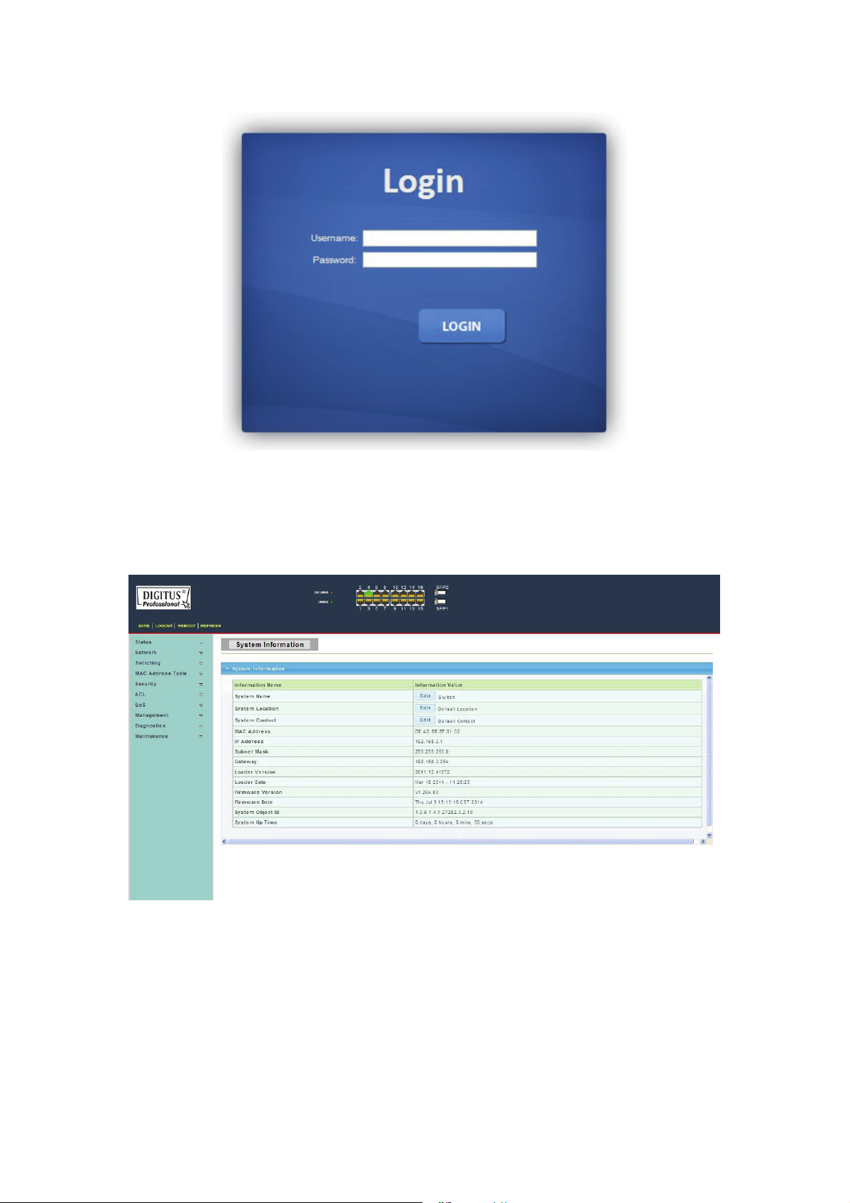
Figure 8 - Login Window
10. Enter the Username and Password (The factory default Username is admin and
Password is admin), and then click “LOGIN” to log in to the Switch configuration window
as below.
Figure 9 - Configuration Window
23
Page 24
Chapter 3 How to Login the Switch (24 port)
3.5 Switch to End Node (24 port)
Use standard Cat.5/5e Ethernet cable (UTP/STP) to connect the Switch to end nodes as
described below. Switch ports will automatically adjust to the characteristics (MDI/MDI-X,
speed, duplex) of the device to which is connected.
Figure 7 - PC Connect
Please refer to the LED Indicator Specification.The LINK/ACT/Speed LEDs for each port
lights on when the link is available.
3.6 How to Login the Switch (24 port)
As the Switch provides Web-based management login, you can configure your computer’s
IP address manually to log on to the Switch. The default settings of the Switch are shown
below.
Parameter Default Value
Default IP address 192.168.2.1
Default user name admin
Default password admin
You can log on to the configuration window of the Switch through following steps:
11. Connect the Switch with the computer NIC interface.
12. Power on the Switch.
13. Check whether the IP address of the computer is within this network segment:
192.168.2.xxx (“xxx” ranges 2~254), for example, 192.168.2.100.
14. Open the browser, and enter
Switch login window appears, as shown below.
http://192.168.2.1
and then press “Enter”. The
24
Page 25
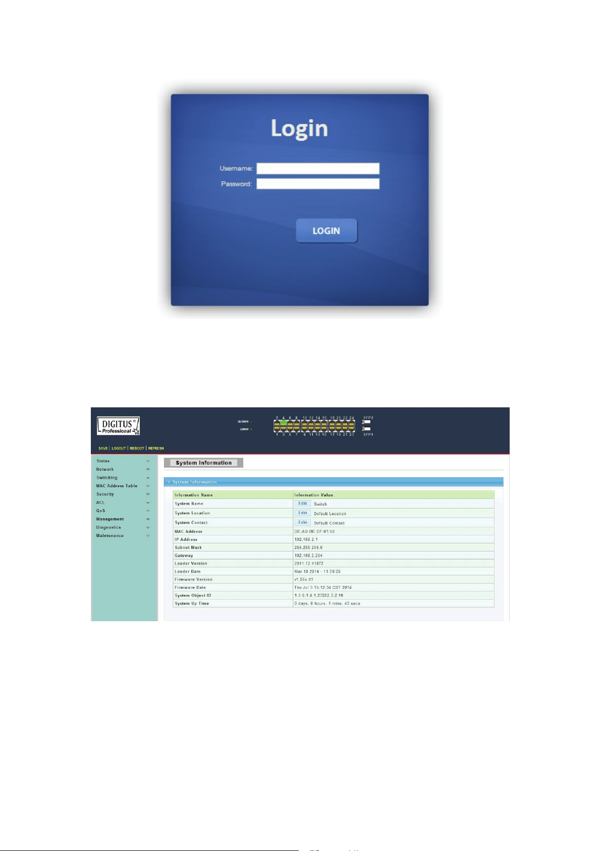
Figure 8 - Login Window
15. Enter the Username and Password (The factory default Username is admin and
Password is admin), and then click “LOGIN” to log in to the Switch configuration window
as below.
Figure 9 - Configuration Window
25
Page 26
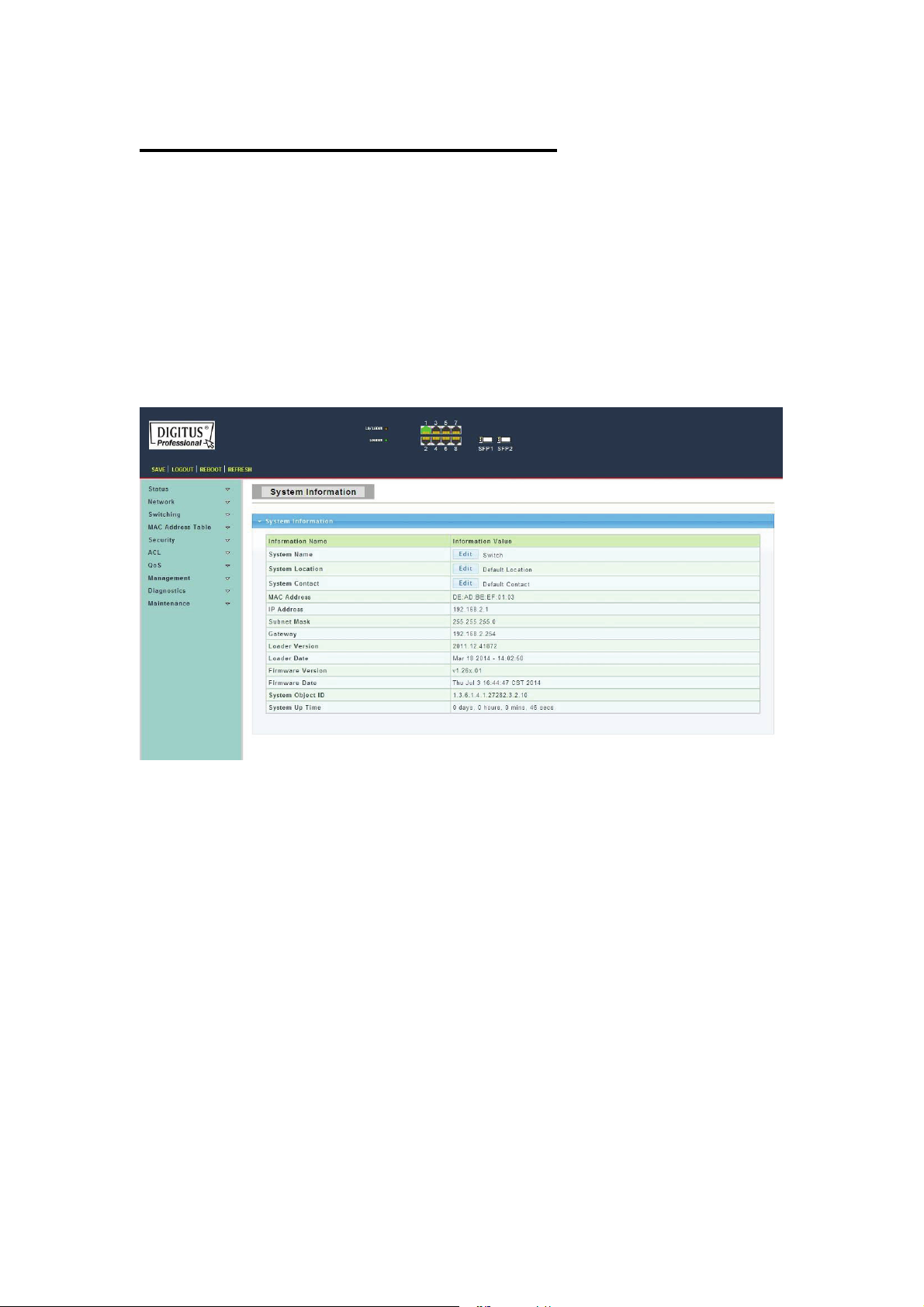
Chapter 4 Switch Configuration
The Web Smart Managed switch software provides rich layer 2 functionality for switches
in your network. This chapter describes how to use Web-based management interface
(Web UI) to configure managed switch software features.
In the Web UI, the left column shows the configuration menu. The top row shows the
switch’s current link status. Green squares indicate the port link is up, while black squares
indicate the port link is down. Below the switch panel, you can find a common toolbar to
provide useful functions for users. The rest of the screen area displays the configuration
settings.
4.1 Status
Use the Status pages to view system information and status.
4.1.1 System Information
To display System Information web page, click Status > System Information
This page allow user to configure System related information and browse some system
information such as MAC address, IP address, firmware version, loader version, etc.
26
Page 27
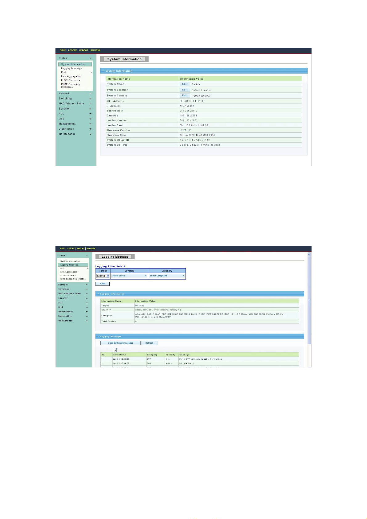
System Name: System name of the switch. This name will also use as CLI prefix of each
line. (“Switch>” or “Switch#”).
System Location: System location of the switch.
System Contact: System contact of the switch.
4.1.2 Logging Message
To display Logging Message web page, click Status > Logging Message
Target: Select the log message source to show on the table.
RAM: Logs store in the RAM disk.
DHCP: Logs store in the FLASH.
Severity: Select severity to filter log messages.
Category: Select category to filter log messages.
4.1.3 Port
The Port configuration page displays port summary and status information.
4.1.3.1 Port Counters
To display Port Counters web page, click Status > Port > Port Counters
27
Page 28
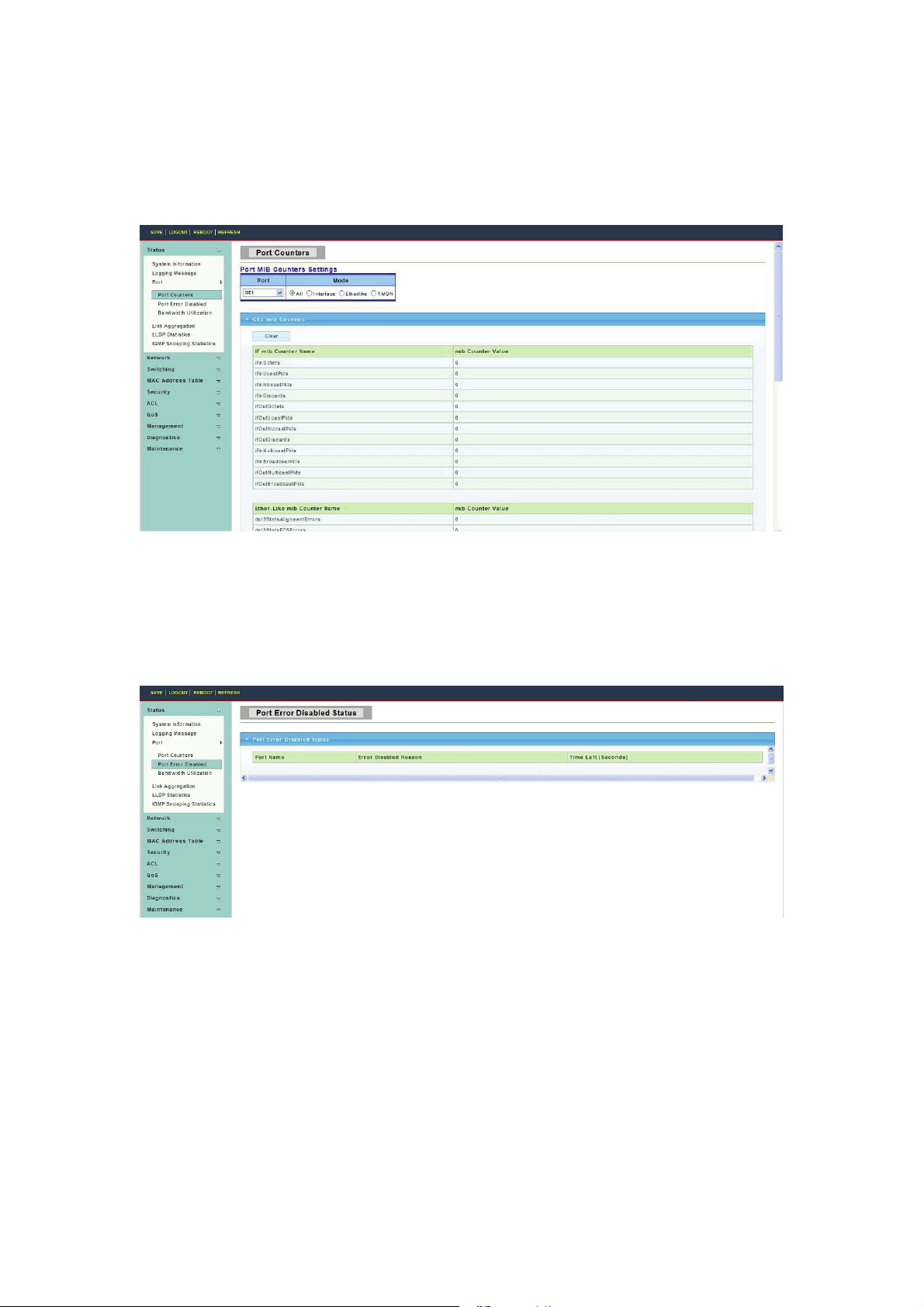
This page displays standard counters on network traffic form the Interfaces, Ethernet-like
and RMON MIB. Interfaces and Ethernet-like counters display errors on the traffic passing
through each port. RMON counters provide a total count of different frame types and sizes
passing through each port.
4.1.3.2 Port Error Disabled
To display Port Error Disabled web page, click Status > Port > Port Error Disabled
This page allow user to browse ports which disabled by some protocols such as BPDU
Guard, Loop back and UDLD. The “Recovery” button will enable those error disabled
ports.
4.1.3.3 Bandwidth Utilization
To display Bandwidth Utilization web page, click Status > Port > Bandwidth Utilization
This page is used to visual display each port TX and RX bandwidth utilization.
28
Page 29

4.1.4 Link Aggregation
To display Link Aggregation web page, click Status > Link Aggregation
This page displays trunk information, report trunk situation, functional ports and alternative
ports.
LAG: LAG ID.
Name: LAG Name.
Typ e: The type of the LAG group: a static LAG or an LACP LAG.
4.1.5 LLDP Statistics
To display LLDP Statistics status, click Status > LLDP Statistics
The Link Layer Discovery Protocol (LLDP) Statistics page displays summary and per-port
information for LLDP frames transmitted and received on the switch.
29
Page 30

Insertions: The number of times the complete set of information advertised by a
particular MAC Service Access Point (MSAP) has been inserted into tables associated
with the remote systems.
Deletions: The number of times the complete set of information advertised by MSAP has
been deleted from tables associated with the remote systems.
Drops: The number of times the complete set of information advertised by MSAP could
not be entered into tables associated with the remote systems because of insufficient
resources.
Age Outs: The number of times the complete set of information advertised by MSAP has
been deleted from tables associated with the remote systems because the information
timeliness interval has expired.
4.1.6 IGMP Snooping Statistics
To display IGMP Snooping Statistics web page, click Status > IGMP Snooping Statistics
This page is used to display IGMP Snooping statistics information.
30
Page 31

4.2 Network
Use the Network page to configure settings for the switch´s network interface.
4.2.1 IP Address
To display IP Address web page, click Network > IP Address
This page allow user to edit IP address, Subnet Mask and Gateway.
Mode: Select the mode of network connection.
Static: Enable static IP address.
DHCP: Enable DHCP to obtain IP information from a DHCP server on the network.
IP Address: If static mode is enabled, enter IP address in this field.
Subnet Mask: If static mode is enabled, enter subnet mask in this field.
Gateway: If static mode is enabled, enter gateway address in this field.
4.2.2 Time Settings
4.2.2.1 System Time
To display System Time web page, click Network > Time Settings > System Time
This page allow user to enable / disable the SNTP (Simple Network Time Protocol), set
the time manually, adjust the time zone and enable or disable the daylight saving
it.
31
Page 32

4.2.2.2 SNTP Settings
To display SNTP Settings web page, click Network > Time Settings > SNTP Settings
SNTP Server Address: The IP address of SNTP/NTP server.
Server Port: The Port Number of SNTP/NTP server.
4.3 Switching
Use the Switching pages to configure settings for the switch ports, trunk, layer 2 protocols
and other switch features.
4.3.1 Port Setting
To display Port Setting web page, click Switching > Port Setting
This page allow user to configure the port status, port speed and duplex mode.
32
Page 33

Port Select: Select one or multiple ports to configure.
Enabled: Port admin state.
Enabled: Enable the port.
Disabled: Disable the port.
Speed: Port speed capabilities.
Auto: Auto speed with all capabilities.
Auto-10M: Auto speed with 10M ability only.
Auto-100M: Auto speed with 100M ability only.
Auto-1000M: Auto speed with 1000M ability only.
Auto-10M/100M: Auto speed with 10M/100M abilities.
10M: Force speed with 10M ability.
100M: Force speed with 100M ability.
1000M: Force speed with 1000M ability.
Duplex: Port duplex capabilities.
Auto: Auto duplex with all capabilities.
Full: Auto speed with full duplex ability only.
Half: Auto speed with half duplex ability only.
Flow Control: Port flow control.
Enable: Enable flow control ability.
Disabled: Disable flow control ability.
4.3.2 Error Disabled
To display Error Disabled web page, click Switching > Error Disabled
33
Page 34

4.3.3 Mirror
To display Local Mirror Setting web page, click Switching > Mirror > Local Mirror
Setting
Port mirroring is copy the TX/RX data flow from the source port to the aiming port,
commonly used in port mirroring.
4.3.4 Link Aggregation
Link aggregation combine multiple Ethernet ports together to form a logical port, it
supports static allocation or LACP.
4.3.4.1 LAG Setting
To display LAG Setting web page, click Switching > Link Aggregation > LAG Setting
This page allow user to configure Ports aggregation rules that is depended on MAC
Address or IP/MAC Address.
34
Page 35

4.3.4.2 LAG Management
To display LAG Management web page, click Switching > Link Aggregation > LAG
Management
This page is used to create new LAG, ports aggregation type and select member ports.
4.3.4.3 LAG Port Setting
To display LAG Port setting web page, click Switching > Link Aggregation > LAG Port
Setting
This page is used to set LAG status, speed and flow control function.
35
Page 36

4.3.4.4 LACP Setting
To display LACP Setting web page, click Switching > Link Aggregation > LACP Setting
This page is used to configure the system Priority of LACP.
System Priority: Configure the system priority of LACP. This decides the system priority
field in LACP PDU.
4.3.4.5 LACP Port Setting
To display LACP Port Setting web page, click Switching > Link Aggregation > LACP
Port Setting
This page is used to set LACP member ports.
36
Page 37

4.3.5 VLAN Management
4.3.5.1 Create VLAN
To display Create VLAN web page, click Switching > VLAN Management> Create
VLAN
This page allow user to add, delete or edit VLAN settings.
VLAN LIST: VLAN LIST for the new VLAN.
VLAN Action: Add or delete VLAN.
VLAN Name Prefix: VLAN Name Prefix for the new VLAN.
4.3.5.2 Interface Settings
To display VLAN Interface Settings web page, click Switching > VLAN Management >
Interface Settings
This page allows the user to set the port type of VLAN, the port VLAN ID and whether the
port should have a tag.
37
Page 38

Port Select : Select one or multiple ports to configure.
Interface VLAN Mode: VLAN port mode
PVID: VLAN ID for the selected ports.
Accepted Type: Port accepted type.
All: Accept tagged and untagged frames.
Tag Only: Only accept tagged frame.
Untag Only: Only accept untagged frame.
Ingress Filtering: Choose filter port open and close.
Uplink: Select port Uplink open or close.
4.3.5.3 Port to VLAN
To display Port to VLAN web page, click Switching > VLAN Management > Port to
VLAN
Select the port’s different behaviors when it works under the VLAN.
4.3.5.4 Port VLAN Membership
To display Port VLAN Membership web page, click Switching > VLAN Management >
Port VLAN Membership
38
Page 39

4.3.5.5 Protocol VLAN Group Setting
To display Protocol VLAN Group Setting web page, click Switching> VLAN> Protocol
VLAN Group Setting
The VLAN group setting sets the same type as a group and transmit it in the specific
VLAN.
Group ID(1-8) : Enter an ID number of the group, between 1 and 8.
Group Name: This is used to identify the new Protocol VLAN group. Type an
alphanumeric string of up to 16 characters.
Frame Type : This function maps packets to protocol-defined VLAN by examining the
type octet within the packet header to discover the type of protocol associated with it.
Ethernet_II: packet type is Ethernet version 2.
IEEE802.3_LLC_Other: packet type is 802.3 packet with LLC other header.
RFC_1042: packet type is RFC 1042 packet.
Protocol Value (0x0600-0xFFFE): Enter the Ether type of the target protocol.
4.3.5.6 Protocol VLAN Port Setting
To display Protocol VLAN Port Setting web page, click Switching> VLAN> Protocol
VLAN Port Setting
39
Page 40

This page is used to divide the port into groups and map it to the VLAN.
Port: Select the specified ports you wish to configure by selecting the port in this list.
Group: Click the corresponding radio button to select a previously configured Group ID or
Group Name.
VLAN: Click the corresponding radio button to select a previously configured VLAN ID or
VLAN Name.
4.3.6 Multicast
4.3.6.1 Properties
To display Properties web page, click Switching > Multicast > Properties
This page is used to set message behavior and iPv4 message forwarding rules.
4.3.6.2 IGMP Snooping
Use the Switching pages to configure settings for the switch network interface.
1. IGMP Setting
To display IGMP Setting web page, click Switching > Multicast > IGMP Snooping >
IGMP Setting
40
Page 41

IGMP Snooping: Select IGMP Snooping enable or disable.
IGMP Snooping Version: Select the IGMP Snooping Version, IGMPv2 or IGMPv3.
IGMP Snooping Report Suppression: Select IGMP Snooping Report Suppression
enable or disable.
2. IGMP Snooping Querier Setting
To display IGMP Snooping Querier Setting web page, click Switching > Multicast >
IGMP Snooping > IGMP Snooping Querier Setting
VLAN ID: Select the VLANs to configure.
Querier State: Set enabling status of IGMP Querier Election on the VLANs.
Enable: Enable IGMP Querier Election.
Disable: Disable IGMP Querier Election.
Version: Select the Querier Version, IGMPv2 or IGMPv3
3. IGMP Static Group
To display IGMP Static Setting web page, click Switching > Multicast > IGMP
Snooping > IGMP Static Group
41
Page 42

This page is used to configure specified ports as static member ports.
4. IGMP Group Table
To display IGMP Group Table web page, click Switching > Multicast > IGMP
Snooping > IGMP Group Table
This page is used to display IGMP Group Table statistics information.
5. IGMP Router Port Setting
To display IGMP Router Port Setting web page, click Switching > Multicast > IGMP
Snooping > IGMP Router Port Setting
This page is used to configure specified ports as static route ports.
42
Page 43

6. IGMP Router Table
To display IGMP Router Table web page, click Switching > Multicast > IGMP
Snooping > IGMP Router Table
This page is used to display IGMP Router Table statistics information.
7. IGMP Forward All
To display IGMP Forward All web page, click Switching > Multicast > IGMP Snooping >
IGMP Forward All
43
Page 44

4.3.6.3 Multicast Throttling Setting
To display Multicast Throttling Setting web page, click Switching > Multicast >Multicast
Throttling Setting
This page is used to limit the port can join one of the biggest Multicast instance.
4.3.6.4 Multicast Filter
This page allow user to create filter instance.
1.Multicast Profile Setting
To display Multicast Profile Setting web page, click Switching > Multicast >Multicast
Filter > Multicast Profile Setting
44
Page 45

2.Multicast Profile Setting
To display IGMP Filter Setting web page, click Switching > Multicast > Multicast Filter >
IGMP Filter Setting
This page is used to filter the port to bind to that instance.
4.3.7 Jumbo Frame
To display Jumbo Frame web page, click Switching > Jumbo Frame
Jumbo Frame: Jumbo frame size. The valid range is 0 bytes – 9216 bytes.
45
Page 46

4.3.8 STP
The Spanning Tree Protocol (STP) is a network protocol that ensures a loop-free topology
for any bridged Ethernet local area network.
4.3.8.1 STP Global Setting
To display STP Global Setting web page, click Switching > STP > STP Global Setting
Enabled: Set the STP status to be enable/disable on the Switch.
BPDU Forward: Choose BPDU packets is a flood or filtering
Path Cost Method:Choose the path overhead is short or long
Force Version: Select the operating mode of STP.
STP-Compatible: 802.1D STP operation.
RSTP-Operation: 802.1w operation.
MSTP-Operation: 802.1s operation.
Configuration Revision: Set the revision of the configuration identification. (Range:
0-65535).
4.3.8.2 STP Port Setting
To display STP Port Setting web page, click Switching > STP > STP Port Setting
46
Page 47

Port Select: Select the port list to specify which ports should apply this setting.
External Path Cost: set the port’s contribution, when it is the Root Port, to the Root Path
cost for the Bridge. (0 means `Auto`).
Edge Port: Set the edge port configuration.
No: Force to false state (as link to a bridge).
Yes: Force to true state (as link to a host).
BPDU Filter: Set the BPDU Filter configuration.
No: Disable BPDU filter function.
Yes: Enable BPDU filter function.
To avoid transmitting BPDU from the specified ports.
BPDU Guard: Set the BPDU Guard configuration.
No: Disable BPDU guard function.
Yes: Enable BPDU filter function.
To drop directly the received BPDU from the specified ports.
P2P MAC: Set the Point-to-Point port configuration.
No: Force to false state.
Yes: Force to true state.
Migrate: Force to try to use the new MST/RST BPDUs, and hence to test the hypothesis
that all legacy systems that do not understand the new BPDU formats have been removed
from the LAN segment on the port(s).
4.3.8.3 CIST Instance Setting
To display CIST Instance Setting
Setting
web page, click Switching > STP > CIST Instance
47
Page 48

Priority: Set the Bridge Priority in the specified CIST instance
Max Hops: Set the value of the maximum number of hops in the region.
Forward Delay: Set the delay time an interface takes to converge from blocking state to
forwarding state.
Max Age: Set the time any switch should wait before trying to change the STP topology
after unhearing Hello BPDU.
Tx Hold Count: Set the Transmit Hold Count used to limit BPDIU transmission rate.
Hello Time: Set the interval between periodic transmissions of BPDU by designated
ports.
4.3.8.4 CIST Port Setting
To display CIST Port Setting
web page, click Switching > STP > CIST Port
Setting
Port Select : Select the port list to specify which ports should apply this setting.
Priority: Set the port priority to the selected ports in the specified CIST instance.
Internal Path Cost: Set the internal path cost to the selected ports in the specified CIST
instance. (0 means `Auto`)
4.3.8.5 MST Instance Setting
To display MST Instance Setting web page, click Switching > STP > MST Instance
Setting
48
Page 49

MSTI ID: Set the MSTI ID to specify the MST instance.
VLAN List: Set the VLAN list.
Priority: Set the bridge priority in the specified MST instance.
4.3.8.6 MST Port Setting
To display MST Port Setting web page, click Switching > STP > MST Port Setting
MST ID: Set the MSTI ID to specify MST instance.
Port Select: Select the port list to specify which ports should apply this setting.
Priority: Set the port priority to the selected ports in the specified MST instance.
Internal Path Cost: Set the internal path cost to the selected ports in the specified MST
instance. (0 means `Auto`)
4.3.8.7 STP Statistics
To display STP Statistics web page, click Switching > STP > STP Statistics
49
Page 50

4.4 Mac Address Table
4.4.1 Static Mac Setting
To display Static Mac Setting web page, click Mac Address Table > Static Mac Setting
MAC Address: The MAC address to which packets will be statically forwarded. If type is
unicast, enter unicast MAC address in this field; if type is multicast, enter multicast MAC
address in this field.
Port: If type is unicast, select the port number of the MAC entry; if type is multicast, select
the port list of the MAC entry.
VLAN: The VLAN ID number of the VLAN on which the above MAC address resides.
4.4.2 MAC Filtering
To display MAC Filtering web page, click Mac Address Table > MAC Filtering
50
Page 51

MAC Address: The MAC address to which packets will be filtered. This must be a unicast
MAC address.
VLAN: The VLAN ID number of the VLAN on which the above MAC address resides.
4.4.3 Dynamic Address Setting
To display Dynamic Address Setting web page, click Mac Address Table > Dynamic
Address Setting
This page is used to set the MAC address of the aging time to study
Aging Time: Set the time needed for aging
4.4.4 Dynamic Learned
To display Dynamic Learned web page, click Mac Address Table > Dynamic Learned
Port: Select the port number to show or clear dynamic MAC entries. If not select any port,
VLAN and MAC address, the whole dynamic MAC table will be displayed or cleared.
VLAN: Select the VLAN to show or clear dynamic MAC entries. If not select any port,
VLAN and MAC address, the whole dynamic MAC table will be displayed or cleared.
MAC Address: Select the MAC address to show or clear dynamic MAC entries. If not
select any port, VLAN and MAC address, the whole dynamic MAC table will be displayed
or cleared.
4.4.5 RMA MAC Address
To display RMA MAC Address web page, click Mac Address Table > RMA MAC Address
51
Page 52

4.5 Security
Use the Security pages to configure settings for the switch security features.
4.5.1 Storm Control
4.3.5.1 Global Setting
To display Global Setting web page, click Security > Storm Control > Global Setting
Unit: Choose storm control unit is pps or bps
Preamble & IFG: Select the rate calculates w/o preamble & IFG (20 bytes).
Excluded: exclude preamble & IFG (20 bytes) when count ingress storm control rate.
Included: include preamble & IFG (20 bytes) when count ingress storm control rate.
4.3.5.2 Port Setting
To display Port Setting web page, click Security > Storm Control > Port Setting
52
Page 53

Port: Select the ports.
Type Enable: Select the type of storm control.
Broadcast: Broadcast packet.
Unknown Multicast: Unknown multicast packet.
Unknown Unicast: Unknown unicast packet.
Rate: Value of storm control rate, Unit: pps (packet per-second) or Kbps (Kbits per-second)
depends on global mode setting. The range is from 0 to 1000000.
4.5.2 802.1X
802.1x is based on the Client/Server access control and authentication protocol. It can
restrict unauthorized users or devices to connect the access port via LAN/WLAN. Before
getting permission from the switch, 802.1x will check the users or devices that connect
with the switch ports. EAPoL data are transmitted between device and switch, when the
device is allowed to access; all data can be transmitted through Ethernet ports.
4.5.2.1 802.1X Setting
To display 802.1X Setting web page, click Security > 802.1X > 802.1X Setting
802.1X: Set the status of 802.1X functionality.
Enable: Enable 802.1X.
Disable: Disable 802.1X.
53
Page 54

4.5.2.2 802.1X Port Setting
To display 802.1X Port Setting web page, click Security > 802.1X > 802.1X Port
Setting
Port: Select the ports to configure their authentication mode.
Mode: The authentication mode.
Force Unauthorized: Force this port to be unconditional unauthorized.
Force Authorized: Force this port to be unconditional authorized.
Authentication: 802.1X authentication.
No Authentication:802.1X disabled.
54
Page 55

Reauthentication Enable: Set the enabling status of 802.1X reauthentication.
Reauthentication Period: Set the reauthentication period of 802.1X if reauthentication is
enabled.
4.5.5.1 Guest VLAN Setting
To display Guest VLAN Setting web page, click Security > 802.1X > Guest VLAN
Setting
4.3.5.1 Authenticated Hosts
To display Authenticated Hosts web page, click Security > 802.1X > Authenticated
Hosts
4.5.3 DHCP Snooping
When the switch opens DHCP-Snooping, it will snoop DHCP message and receive DHCP
Request and abstract and record the IP address and MAC address from DHCP ACK
message. Besides, DHCP-Snooping admits one physical port setting as creditable port or
55
Page 56

discreditable ports. Creditable ports can receive and forward the DHCP Offer message, on
the contrary, the discreditable port will lose the DHCP Offer message. In that way, the
switch can pick out the fake DHCP Server and make sure that the client gets legal IP
address from DHCP Server.
4.5.3.1 Global Setting
To display Global Setting web page, click Security > DHCP Snooping > Global Setting
This page is used to open DHCP Snooping function
DHCP Snooping: enable or disable DHCP Snooping function
4.5.3.2 VLAN Setting
To display VLAN Setting web page, click Security > DHCP Snooping > VLAN Setting
Specific VLAN starts DHCP Snooping
4.5.3.3 Port Setting
To display Port Setting web page, click Security > DHCP Snooping > Port Setting
This page allow user to configure the specific port as DHCP Snooping trust port.
56
Page 57

4.5.3.4 Statistics
To display Statistics web page, click Security > DHCP Snooping > Statistics
This page shows statistics of each port´s DHCP Snooping state information.
4.5.3.5 Rate Limit
To display Rate Limit web page, click Security > DHCP Snooping > Rate Limit
57
Page 58

4.5.3.6 DHCP Option82 Global Setting
To display DHCP Option82 Global Setting web page, click Security> DHCP Snooping >
Option82 Global Setting
This page is used to configure DHCP Snooping support Option82 strategy.
4.5.3.7 Option82 Port Setting
To display Option82 Port Setting web page, click Security> DHCP Snooping > Option82
Port Setting
To the specified port configuration of receiving containing Option 82 options request
packet port handling strategy.
58
Page 59

4.5.3.8 Option82 Circuit-ID Setting
To display Option82 Circuit-ID Setting web page, click Security> DHCP Snooping >
Option82 Circuit-ID Setting
This page allow user to edit circuit ID content in the option82.
4.5.4 Port Security
To display Port Security web page, click Security> Port Security
Ports Security can set port isolation and specific behavior.
59
Page 60

Port Select: Select one or multiple ports to configure.
Security: Port security function. It constraint how many MAC addresses can be learned
by a port and drop new one when reach the limitation.
Enable: Enable port security function.
Disable: Disable port security function.
Max L2 Entry: The total number of MAC addresses entry, which can be learned by a port.
4.5.5 AAA
4.5.5.1 Login List
To display Login List web page, click Security > AAA > Login List
This page allow user to add, edit or delete login authentication list settings (The“default”
list cannot be deleted.).The line combined to this list will authenticate login user by
methods in this list. If the first method is failed, it will try to use the next priority method to
authenticate if it exists.
List Name:
New login authentication list name. This name should be different from other existing lists.
60
Page 61

Method 1: Select first priority of login authentication method.
Local: Use local accounts database to authenticate.
Tacacs+: Use remote TACACS+ server to authenticate.
Radius: Use remote Radius server to authenticate. Not supported now, it will be supported in
the future.
Enable: Use local enable password to authenticate.
Method 2: Select second priority of login authentication method.
Local: Use local accounts database to authenticate.
Tacacs+: Use remote TACACS+ server to authenticate.
Radius: Use remote Radius server to authenticate. Not supported now, it will be supported in
the future.
Enable: Use local enable password to authenticate.
Method 3: Select third priority of login authentication method.
Local: Use local accounts database to authenticate.
Tacacs+: Use remote TACACS+ server to authenticate.
Radius: Use remote Radius server to authenticate. Not supported now, it will be supported in
the future.
Enable: Use local enable password to authenticate.
Method 4: Select forth priority of login authentication method.
Local: Use local accounts database to authenticate
Tacacs+: Use remote TACACS+ server to authenticate.
Radius: Use remote Radius server to authenticate. Not supported now, it will be supported in
the future.
Enable: Use local enable password to authenticate
4.5.5.2 Enable List
To display Login List web page, click Security> AAA > Enable List
This page allow user to add, edit or delete enable authentication list settings (The
“default” list cannot be deleted.). The line combined to this list will authenticate user
who issuing the‘enable’ command by methods in this list. If the first method is failed, it
will try to use the next priority method to authenticate if it exists.
61
Page 62

List Name: New enable authentication list name. This name should be different from
other existing lists.
Method 1: Select first priority of enable authentication method.
Enable: Use local enable password to authenticate
Tacacs+: Use remote TACACS+ server to authenticate.
Radius: Use remote Radius server to authenticate. Not supported now, it will be supported in
the future.
Method 2: Select second priority of enable authentication method.
Enable: Use local enable password to authenticate
Tacacs+: Use remote TACACS+ server to authenticate.
Radius: Use remote Radius server to authenticate. Not supported now, it will be supported in
the future.
Method 3: Select third priority of enable authentication method.
Enable: Use local enable password to authenticate.
Tacacs+: Use remote TACACS+ server to authenticate.
Radius: Use remote Radius server to authenticate. Not supported now, it will be supported in
the future.
4.5.5.3 Accounting List
To display Accounting List web page, click Security> AAA > Accounting List
This page allow user to add, edit or delete accounting list settings (The “default” list cannot
be deleted.). The line combined to this list will accounting user who entering CLI shell by
methods in this list. If the first method is failed, it will try to use the next priority method to
accounting if it exists.
List Name:
New accounting list name. This name should be different from other existing lists.
Record Type:
Select accounting record type.
None: No accounting.
Start-stop: Record start and stop without waiting.
Stop-only: Record stop when service terminates.
62
Page 63

Method 1: Select first priority of exec accounting method.
Tacacs+: Use remote TACACS+ server to accounting.
Radius: Use remote Radius server to accounting. Not supported now, it will be supported in
the future.
Method 2: Select second priority of exec accounting method.
Tacacs+: Use remote TACACS+ server to accounting.
Radius: Use remote Radius server to accounting. Not supported now, it will be supported in
the future.
4.5.5.4 Accounting Update
To display Accounting Update web page, click Security> AAA > Accounting Update
4.5.6 Tacacs+ Server
To display Tacacs+ server web page, click Security> AAA >Tacacs+ server
This page allow user to add, edit or delete TACACS+ server settings.
4.5.7 Radius server
To display Radius server web page, click Security > AAA > Radius server
63
Page 64

This page is used to set up radius server.
4.5.8 Access
4.5.8.1 Console
To display Console web page, click Security > Access > Console
This page allow user to combine all kinds of AAA lists to console line. The user accesses
switch from console will be authenticated, authorized and accounted by AAA lists we
combined here.
Login Authentication List: Select one of the login authentication lists we configured in
“Login List” page.
Enable Authentication List: Select one of the enable authentication lists we configured
in “Enable List” page.
EXEC Authorization List: Select one of the EXEC authorization lists we configured in
“EXEC List” page.
Commands Authorization List: Select one of the commands authorization lists we
configured in “Commands List” page.
64
Page 65

EXEC Accounting List: Select one of the EXEC accounting lists we configured in
“Accounting List” page.
Session Timeout: Set session timeout minutes for user access CLI from console line. If
user does not response after session timeout minute, CLI will logout automatically. 0
minutes means never timeout.
4.5.8.2 Telnet
To display Telnet web page, click Security > Access > Telnet
This page allow user to combine all kinds of AAA lists to telnet line. The user accesses
switch from telnet will be authenticated, authorized and accounted by AAA lists we
combined here.
Telnet Service: Set remote service disable or enable
Login Authentication List: Select one of the login authentication lists we configured in
“Login List” page.
Enable Authentication List: Select one of the enable authentication lists we configured
in “Enable List” page.
EXEC Authorization List: Select one of the EXEC authorization lists we configured in
“EXEC List” page.
Commands Authorization List: Select one of the commands authorization lists we
configured in “Commands List” page.
EXEC Accounting List: Select one of the EXEC accounting lists we configured in
“Accounting List” page.
Session Timeout: Set session timeout minutes for user access CLI from telnet line. If
user does not response after session timeout minute, CLI will logout automatically.
4.5.8.3 HTTP
To display HTTP web page, click Security > Access > HTTP
This page allow user to combine all kinds of AAA lists to HTTP line. The user accesses
switch WEBUI from HTTP will be authenticated by AAA lists we combined here.
65
Page 66

HTTP Server:set HTTP Server disable or enable.
Login Authentication List: Select one of the login authentication lists we configured in
“Login List” page.
Session Timeout: Set session timeout minutes for user access WEB from HTTP protocol.
If user does not response after session timeout minute, WEB UI will logout automatically.
0 minutes means never timeout.
4.5.8.4 HTTPS
To display HTTPS web page, click Security > Access > HTTPS
This page allow user to combine all kinds of AAA lists to HTTPS line. The user accesses
switch WEBUI from HTTPS will be authenticated by AAA lists we combined here.
HTTPS Server: Set HTTPS Server disable or enable.
Login Authentication List: Select one of the login authentication lists we configured in
“Login List” page.
Session Timeout: Set session timeout minutes for user access WEB from HTTPS
protocol. If user does not response after session timeout minute, WEBUI will logout
automatically. 0 minutes means never timeout.
66
Page 67

4.6 ACL
4.6.1 MAC-Based ACL
To display MAC-Based ACL web page, click ACL > MAC-Based ACL
This page allow user to set name for MAC-Based ACL.
ACL Name: Enter ACL name in this field.
4.6.2 MAC-Based ACE
To display MAC-Based ACE web page, click ACL > MAC-Based ACE
This page allow user to set Based on MAC address expanding ACL list, matching
corresponding MAC and setting the ports as drop or forward.
4.6.3 IPv4-Based ACL
To display IPv4-Based ACL web page, click ACL > IPv4-Based ACL
This page allow user to set name for IPv4-Based ACL.
67
Page 68

4.6.4 IPv4-Based ACE
To display IPv4-Based ACE web page, click ACL > IPv4-Based ACE
This page allow user to set based on IPv4 expanding ACL Peer Guardian and matching
corresponding IP and setting the port as drop or forward.
4.6.5 ACL Binding
To display ACL Binding web page, click ACL > ACL Binding
This page allow user to bounding with accordingly ACL rules, port bounding ACL rules.
68
Page 69

4.7 QoS
Use the QoS pages to configure settings for the switch QoS interface.
4.7.1 General
4.7.1.1 QoS Properties
To display QoS properties web page, click QoS > General > QoS properties
This page allow user to set QoS mode, basic or advanced.
4.7.1.2 Port Settings
To display Port Settings web page, click QoS > General > Port Settings
This page is used to give the QoS instance port configuration.
4.7.1.3 Queue Settings
To display Queue Setting web page, click QoS > General > Queue Settings
This page allow user to set the QoS instance queue scheduling model.
69
Page 70

4.7.1.4 COS Mapping
To display COS Mapping web page, click QoS > General > COS Mapping
The page allow user to set QoS instance of COS Mapping.
4.7.1.5 DSCP Mapping
To display DSCP Mapping web page, click QoS > General > DSCP Mapping
The page allow user to set QoS instance of DSCP Mapping.
70
Page 71

4.7.1.5 IP Precedence Mapping
To display IP Precedence Mapping web page, click QoS > General > IP Precedence
The page allow user to set QoS instance of IP Precedence Mapping.
4.7.2 QoS Basic Mode
4.7.2.1 Global Settings
To display Global Settings web page, click QoS > QoS Basic Mode > Global Settings
This page allow user to set QoS for trust mode on basic mode global settings.
71
Page 72

4.7.2.2 Port Settings
To display Port Settings web page, click QoS > QoS Basic Mode > Port Settings
This page allow user to set QoS port setting enabled or disabled.
4.7.3 QoS Advanced Mode
4.7.3.1 Global Settings
To display Global Settings web page, click QoS > QoS Advanced Mode > Global
Settings
This page allow user to set the default QoS mode state under advanced mode global
settings trust mode.
72
Page 73

4.7.3.2 Class Mapping
To display Class Mapping web page, click QoS > QoS Advanced Mode > Class
Mapping
This page allow user to create a QoS class, which is used to link the ACL.
4.7.3.3 Aggregate Policer
To display Aggregate Policer web page, click QoS > QoS Advanced Mode > Aggregate
Policer
4.7.3.4 Policy Table
To display Policy Table web page, click QoS > QoS Advanced Mode > Policy Table
73
Page 74

4.7.3.5 Policy Class Maps
To display Policy Class Maps web page, click QoS > QoS Advanced Mode > Policy
Class Maps
4.7.3.6 Policy Binding
To display Policy Binding web page, click QoS > QoS Advanced Mode > Policy Binding
74
Page 75

4.7.4 Rate Limit
4.7.4.1 Ingress Port Settings
To display Ingress Port Settings web page, click QoS > Rate Limit > Ingress Port
Settings
This page allow user to set ingress port monitor.
4.7.4.2 Ingress VLAN Settings
To display Ingress VLAN Settings web page, click QoS > Rate Limit > Ingress VLAN
Settings
This page is used to set the bandwidth of the VLAN entry control.
4.7.4.3 Egress Port Settings
To display Egress Port Settings web page, click QoS > Rate Limit > Egress Port
Settings
This page is used to set the egress port monitor.
75
Page 76

4.7.4.4 Egress Queue Settings
To display Egress Queue Settings web page, click QoS > Rate Limit > Egress Queue
Settings
The page is used to set the egress lined up bandwidth monitor.
4.8 Management
4.8.1 LLDP
LLDP is a one-way protocol; there are no request/response sequences. Information is
advertised by stations implementing the transmit function, and is received and processed
by stations implementing the receive function.
76
Page 77

4.8.1.1 LLDP Global Settings
To display LLDP Global Settings web page, click Management > LLDP > LLDP Global
Settings
Enabled: Enable/ Disable LLDP protocol on this switch.
Transmission Interval: Select the interval at which frames are transmitted. The default is
30 seconds, and the valid range is 5–32768 seconds.
Hold time Multiplier: Select the multiplier on the transmit interval to assign to TTL
(Range 2–10, default = 4).
Reinitialization Delay: Select the delay before a re-initialization (range 1–10 seconds,
default = 2).
4.8.1.2 LLDP Port Settings
To display LLDP Port Settings web page, click Management > LLDP > LLDP Port
Settings
77
Page 78

Port Select: Select specified port or all ports to configure transmission state.
State: Select the transmission state of LLDP port interface.
Disable: Disable the transmission of LLDP PDUs.
RX Only: Receive LLDP PDUs only.
TX Only: Transmit LLDP PDUs only.
TX And RX: Transmit and receive LLDP PDUs both select specified port or all port configure
transmission state.
Port Select: Select specific ports.
Optional TLV Select: Select Optional TLVs.
4.8.1.3 LLDP Local Device
To display LLDP Local Device web page, click Management > LLDP > LLDP Local
Device
Use the LLDP Local Device page to view information about devices on the network for
which the switch has received LLDP information.
4.8.1.4 LLDP Remote Device
To display LLDP Remote Device web page, click Management > LLDP > LLDP Remote
Device
Use the LLDP Remote Device page to view information about remote devices for which
the switch has received LLDP information.
78
Page 79

4.8.1.5 LLDP Network Policy
To display LLDP Network Policy web page, click Management > LLDP > LLDP Network
Policy
4.8.1.6 MED Port Setting
To display MED Port Setting web page, click Management > LLDP > MED Port Setting
79
Page 80

4.8.1.7 LLDP Overloading
To display LLDP Overloading web page, click Management > LLDP > LLDP
Overloading
4.8.2 SNMP
4.8.2.1 SNMP Setting
To display SNMP Setting web page, click Management > SNMP > SNMP Setting
State: SNMP daemon state
Enabled: Enable SNMP daemon
Disabled: Disable SNMP daemon
4.8.2.2 SNMP View
To display SNMP View web page, click Management > SNMP > SNMP View
This page is used to configure SNMP view, used in the SNMP message Management
variables (OID) to describe the switch in the Management object. MIB (Management
Information Base) is a set of monitoring network equipment Management variables. View
is used to control, variable is how to be managed.
80
Page 81

4.8.2.3 SNMP Access Group
To display SNMP Access Group web page, click Management > SNMP > SNMP Access
Group
This page is used to configure SNMP group, within the group the user can set read-only or
write only.
4.8.2.4 SNMP Community
To display SNMP Community web page, click Management > SNMP > SNMP
Community
SNMP v1 and SNMP v2c uses the group Name (Community Name) certification, which is
similar to the password. If use SNMP v1 and SNMP v2c, after configuring SNMP view, the
SNMP community can be directly configured.
81
Page 82

4.8.2.5 SNMP User
To display SNMP User web page, click Management > SNMP > SNMP User
This page is used to create SNMP user under the group and the group with the same level
of security and access control permissions.
4.8.2.6 SNMPv1,2 Notification Recipients
To display SNMPv1,2 Notification Recipients web page, click Management > SNMP >
SNMPv1,2 Notification Recipients
82
Page 83

4.8.2.7 SNMPv3 Notification Recipients
To display SNMPv3 Notification Recipients web page, click Management > SNMP >
SNMPv3 Notification Recipients
4.8.2.8 SNMP Engine ID
To display SNMP Engine ID web page, click Management > SNMP > SNMP Engine ID
83
Page 84

4.8.2.9 SNMP Remote Engine ID
To display SNMP Remote Engine ID web page, click Management > SNMP > SNMP
Remote Engine ID
4.8.3 RMON
4.8.3.1 RMON Statistics
To display RMON Statistics web page, click Management > RMON > RMON Statistics
4.8.3.2 RMON Event
To display RMON Event web page, click Management > RMON > RMON Event
This page is used to configure RMON event group.
84
Page 85

4.8.3.3 RMON Event Log
To display RMON Event Log web page, click Management > RMON > RMON Event Log
4.8.3.4 RMON Alarm
To display RMON Alarm web page, click Management > RMON > RMON Alarm
This page is used to configure RMON statistics group and alarm group.
4.8.3.5 RMON History
To display RMON History web page, click Management > RMON > RMON History
This page is used to configure the RMON history group.
85
Page 86

4.8.3.6 RMON History Log
To display RMON History Log web page, click Management > RMON > RMON History
Log
4.9 Diagnostics
Use the Diagnostics pages to configure settings for the switch diagnostics feature or
operating diagnostic utilities.
4.9.1 System Status
To display System Status Log web page, click Diagnostics > System Status
4.9.2 Ping Test
To display Ping Test Log web page, click Diagnostics > Ping Test
86
Page 87

IP Address: The IP address of ping target.
Count: How many times to send ping request packet.
Interval: Time interval between each ping request packet.
Size: The size of ping packet.
Ping Results: After ping finished, results will show in this field.
4.9.3 Logging Setting
4.9.3.1 Logging Service
To display Logging Service web page, click Diagnostics > Logging Setting > Logging
Service
4.9.3.2 Local Logging
To display Local Logging web page, click Diagnostics > Logging Setting > Local
Logging
87
Page 88

Target: Select the target to store log message
RAM: Store log messages in RAM disk. All log messages will disappear after system reboot.
FLASH: Store log messages in FLASH. All log messages will not disappear after system
reboot.
Severity: Select severity of log messages, which will be stored.
4.9.3.3 Remote Logging
To display Remote Logging web page, click Diagnostics > Logging Setting > Remote
Logging
Server Address: The IP address of remote log server.
Server Port: The Port number of remote log server.
Severity: Select severity of log messages, which will be sent.
4.9.4 Factory Default
To display Factory Default web page, click Diagnostics > Factory Default
This page allow user to restore switch to factory default by pushing “Restore” button.
4.9.5 Reboot Switch
To display Reboot Switch web page, click Diagnostics > Reboot Switch
This page allow user to reboot the switch by pushing“Reboot”button.
88
Page 89

4.10 Maintenance
Use the Maintenance pages to configure settings for the switch network interface, and
how the switch connects to a remote server to get services.
4.10.1 Backup Manager
To display Backup Manager web page, click Maintenance > Backup Manager
This page allow user to backup the firmware image or configuration file on the switch to
remote TFTP server or host file system through HTTP protocol.
Backup Method: Select backup method
TFTP: Use TFTP to backup
HTTP: Use HTTP to backup
Server IP: IP address of the TFTP server. If the TFTP backup method is selected, the IP
address of the TFTP server must be assigned.
Backup Type: Select Backup Type
89
Page 90

4.10.2 Upgrade Manager
To display Upgrade Manager web page, click Maintenance > Upgrade Manager
This page allow user to upgrade new firmware image or configuration file to the switch
from remote TFTP server or select file from web browser.
Upgrade Method: Select upgrade method
TFTP: Use TFTP to upgrade
HTTP: Use HTTP to upgrade
Server IP: IP address of the TFTP server. If the TFTP upgrade method is selected, the IP
address of the TFTP server must be assigned.
File Name: Firmware image or configuration file name on remote TFTP server. If the
TFTP upgrade method is selected, the file name must be specified.
Browse file: If the HTTP upgrade method is selected, the browse file field allows you to
select any file on host operating system.
Upgrade Type: Select Backup Type
4.10.3 Configuration Manager
To display Configuration Manager web page, click Maintenance > Configuration
Manager
90
Page 91

4.10.4 Account Manager
To display Account Manager web page, click Maintenance > Account Manager
This page allow user to add or delete switch local user database for authenticating.
User Name: User name for new account.
Password Type: Select password type for new account.
Clear Text: Password without encryption
Encrypted: Password with encryption
No Password: No password for the new account.
Password: If the password type is not “No Password”, the password must be specified.
Retype Password: Retype password to make sure the password is exactly you typed
before in “Password” field.
Privilege Type: Select privilege level for new account.
Admin: Allow to change switch settings.
User: See switch settings only. Not allow to change it.
If AAA feature is enabled, we have one more privilege type to allow user adding privilege
value for this account.
User Name: User name for new account.
Password Type: Select password type for new account.
Clear Text: Password without encryption
Encrypted: Password with encryption
No Password: No password for the new account.
91
Page 92

Password: If the password type is not “No Password”, the password must be specified.
Retype Password: Retype password to make sure the password is exactly you typed
before in “Password” field.
Privilege Type: Select privilege level for new account.
Admin: Allow to change switch settings.
User: See switch settings only. Not allow to change it.
Other: Assign privilege level value in Privilege value field.
Privilege Value: If the account privilege type is “Other”, set the privilege level for this
account here. The valid privilege level is from 2 to 14.
4.10.5 Enable Password
To display Enable Password web page, click Maintenance > Enable Password
This page allow user to modify the enable password. In command line interface, user can
use “enable” command to change their privilege level to “Admin”. After “enable” command
is issued, user need to type the enable password to change their privilege level.
Password Type: Select password type for enable password.
Clear Text: Password without encryption
Encrypted: Password with encryption
Password: Password string.
Retype Password: Retype password to make sure the password is exactly you
typed before in “Password” field.
92
Page 93

Hinweis: Bei falscher Installation und unsachgemäßem Gebrauch im Wohnbereich kann das
Gerät Störungen bei Rundfunkgeräten und anderen elektronischen Geräten verursachen. Ein
sachgemäßer Gebrauch liegt vor, wenn das Gerät, soweit durchführbar, mit geschirmten
Anschlusskabeln betrieben wird (bei Netzwerkprodukten zusätzlich geschirmter Kabel der
Kategorie 5e und höher). Das Gerät wurde getestet und liegt innerhalb der Grenzen für
Computerzubehör der Klasse A gemäß den Anforderungen nach EN 55022. Warnung: Dieses
Produkt entspricht der Prüfklasse A –es kann im Wohnbereich Funkstörungen verursachen; in
diesem Fall kann vom Betreiber verlangt werden, angemessene Maßnahmen durchzuführen
und dafür aufzukommen. Konformitätserklärung: Das Gerät erfüllt die EMV-Anforderungen nach
EN 55022 Klasse A für ITE und EN 55024. Geräte mit externer oder eingebauter
Spannungsversorgung erfüllen weiterhin die Anforderungen nach EN 61000-3-2 und EN
61000-3-3. Damit sind die grundlegenden Schutzanforderungen der EMV-Richtlinie
2004/108/EC erfüllt. Die CE-Konformität wurde nachgewiesen. Die entsprechenden Erklärungen
sind beim Hersteller hinterlegt.
www.assmann.com
ASSMANN Electronic GmbH
Auf dem Schüffel 3
58513 Lüdenscheid
Germany
93
 Loading...