

Page 1

Industrial Optical Switch
User Manual
Page 2
1. introduction
The Industrial Switch is in an IP40 rugged strong case, Industrial Level-4
EMC design, which can work steady in harsh environments. It is an ideal
solution to providing network by supporting Auto-Negotiation and LED
indicators.
The device supports redundant power system (12~56VDC) to guarantee
the network stability. It is flexible and convenient for two Installation
methods: DIN-Rail mounted and Wall-mounted. For PoE version,
supporting up to 30W power per port for any remote IEEE802.3af/at
powered device (PD) such as PoE IP cameras and PoE wireless LAN
access point.
2. Package content
Please check the following items in the package before installing the
device
Industrial media converter/Switch 1piece
User manual 1copy
DIN-rail or wall mounting kit 1piece
Page 3
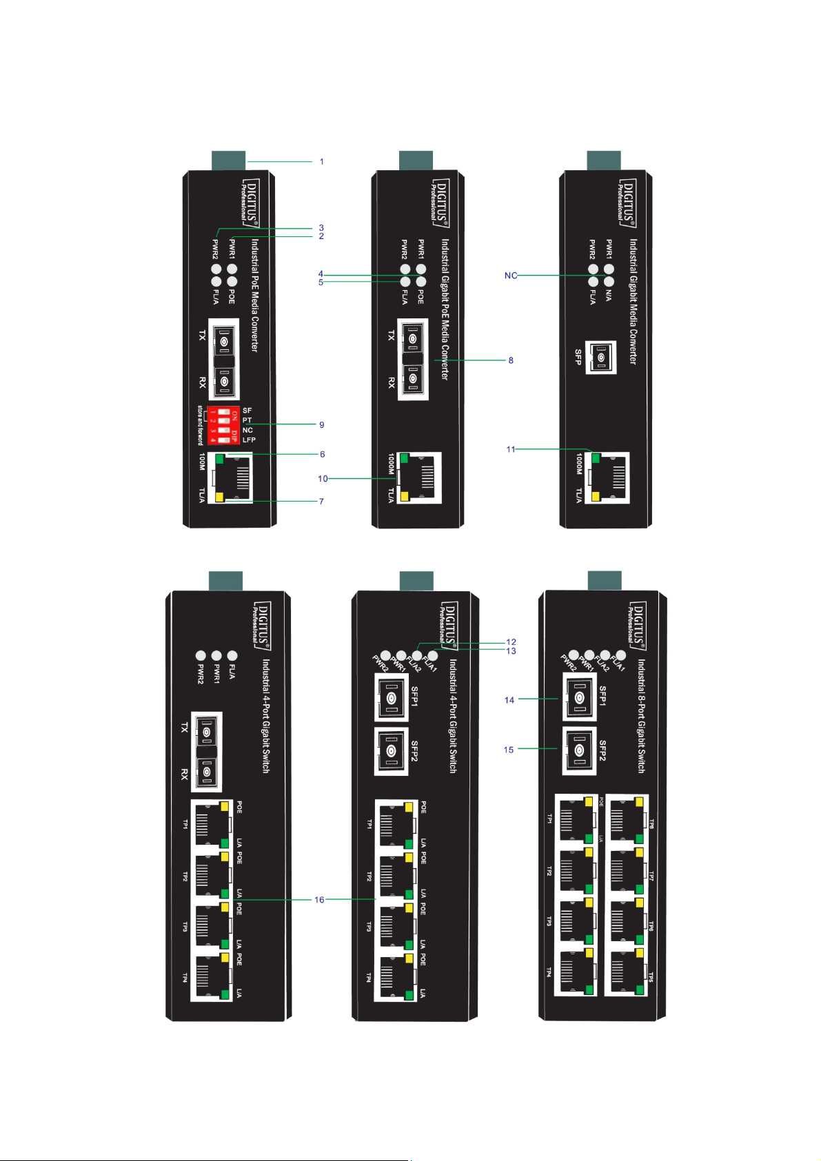
3. The panels and LED indicators
Page 4
Mark Name Function
1 Terminal block Power supply and Grounding port
2 PWR1 “On”: Power 1 is on and normal
3 PWR2 “On”: Power 2 is on and normal
4 PoE “On”: Power over PoE port is on and normal
5 FL/A
6 100M “On”: 100Mbps
7 TL/A, L/A
8 Optical port
9 DIP Switch To control the LFP function
10 RJ45 port Copper cable connector
11 1000M “On”: 1000Mbps
12 FL/A2
13 FL/A1
14 SFP1 SFP mould port 1
15 SFP2 SFP mould port 2
16 1×4 RJ45 Copper cable connector
“On”: Fiber link is in correct connection.
“Blink”: Signal packet goes through Fx end
“On”: Electric link is in correct connection.
“Blink”: Signal packet goes through Tx end
Fiber optic connecting port.
Connector type: SC, FC, ST, LC
“On”: SFP2 Fiber link is in correct connection.
“Blink”: Signal packet goes through SFP2 Fx end
“On”: SFP1 Fiber link is in correct connection.
“Blink”: Signal packet goes through SFP1 Fx end
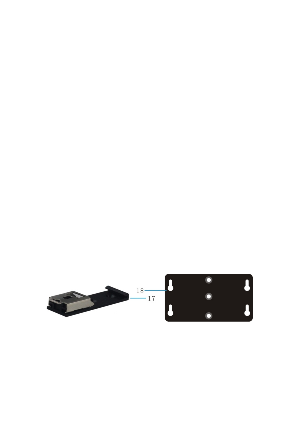
17 DIN kit DIN-rail mounting kit
18 Ear kit Wall mounting kit
19 N/A Not applicable
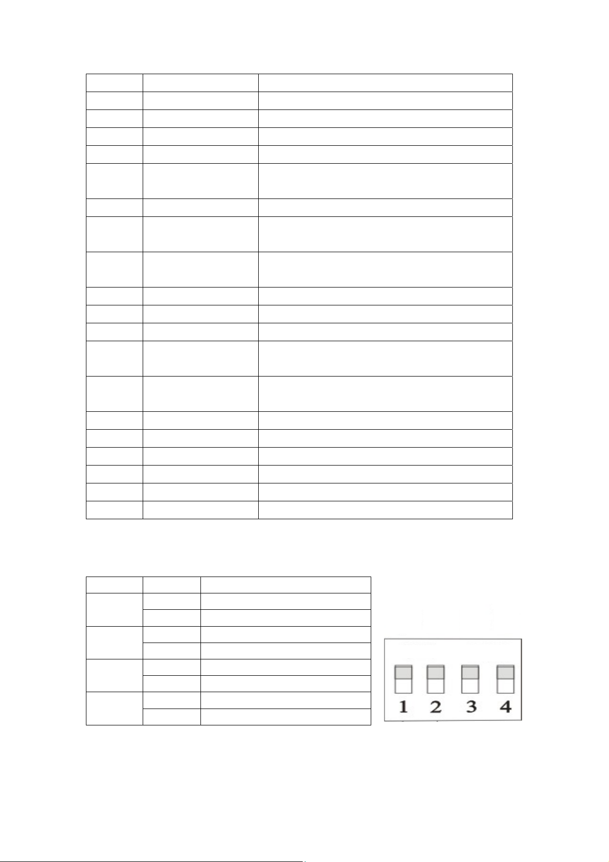
DIP switch (if available)
Switch Status Function
1 On Pass through mode
Off Switch mode
2 On Modified cut through mode
Off Store-and-forward mode
3 On No available
Off /
4 On Enable LFP function(default)
Off Disable LFP function
SF
Store and forward
PT
ON
NC
DIP
LFP
Page 5

4. Installation
4.1 DIN-rail installation
DIN-Rail
Pic 1
Pic 2
Page 6

DIN-Rail
Pic 3
The DIN installation is based on the Pic 1 and Pic 2. Unload is based on
the Pic 3, then Pic2 and Pic 1.
4.2 Wall-mounted installation
Pic 4 Pic 5 Pic 6
Fix hanging ears in the switch, as shown in figure 4
Page 7

Select 4 suitable screws (diameter of screw head should be less than 6
mm, diameter of screw should be less than3.5 mm diameter, as shown
in Pic 5) and fix the device on the wall as Pic 6, don’t completely tighten
the screws, keep some space about 2mm.
Install hanging ear of switch alignment inside the four screws, then press
the switch down, ensure the hanging ear has been fix properly, and turn
the screw.
4.3 Wall-mounted installation
Input terminal of the switch for 6PIN plug type terminals, V1+ and V1- is
for power supply 1 (PWR1), V2 + and V2- is for power supply 2 (PWR2)
and GND for earthing terminal, as shown in Pic 7.
Power 1 and power 2 input voltage range is 12VDC ~ 56VDC, V1+, and
V2+ are positive, V1- and V2- are negative, and the equipment supports
anti reverse function; Two sets of power can be simultaneously accessed.
So if one of the power failures, the switch is still able to work.
PWR1 PWR2 GND
Pic 7
DC 12~56V
Page 8

4.4 Dimensions
Industrial PoE Media Converter
Industrial PoE Switch
4.5 Copper cable connection
The standard RJ45 receptacle/connector
There are 8 wires on a standard UTP/STP cable and each wire is color
coded. The following shows the pin allocation and color of straight
through cable and crossover cable connection:
Page 9

Straight Cable
SIDE 1 SIDE 2
Cross Over Cable
SIDE 1
SIDE 2
1 = White/Orange
2 = Orange
3 = White/Green
4 = Blue
5 = White/Blue
6 = Green
7 = White/Brown
8 = Brown
1 = White/Orange
2 = Orange
3 = White/Green
4 = Blue
5 = White/Blue
6 = Green
7 = White/Brown
8 = Brown
SIDE 1 SIDE 2
SIDE 1
SIDE 2
1 = White/Orange
2 = Orange
3 = White/Green
4 = Blue
5 = White/Blue
6 = Green
7 = White/Brown
8 = Brown
1 = White/Green
2 = Green
3 = White/Orange
4 = Blue
5 = White/Blue
6 = Orange
7 = White/Brown
8 = Brown
4.6 Fiber cable connection
LC-Port Pinouts
LC-Port to LC-Port Cable Wiring
Cable Wiring
LC-Port Pinouts
Page 10

5. Technical parameters
Power supply
Input voltage: 12V~56V (redundant dual power)
PSE Power: 0~30W
PoE Pin: 1/2+, 3/6-
Copper Port
Connector: RJ-45 connector
Data Rate: 10/100Mbps Auto,
10/100/1000Mbps Auto
Twisted Pair cable: Cat5 UTP cable
Transmission distance: 100 meter
Fiber Port
Connector: SC (default), FC/ST/SFP (optional)
Data Rate: 155Mbps, 1.25Gbps
Fiber Type: SM 9/125μm,
MM 50/125μm, 62.5/125μm
Transmission distance: 20km ~ 120km
Environment
Storage temperature: -40~95°C
Operating temperature: -40~85°C
Relative humidity: 5%-90%
Mechanism
Enclosure: IP40, Black, Metal shell
Mounting: DIN-rail, Wall
Agreement
IEEE 802.3, IEEE 802.3u, IEEE 802.3ab, IEEE 802.3z, IEEE 802.3x
IEEE802.3af, IEEE802.3at
Page 11

6. Warning
This product is suitable for indoor application.
Place the dust cover on the fiber interface when not in use.
It is dangerous to stare at the fiber transmitter with the
naked eyes.
Optical fiber transceivers must be used in pair.
Single optical fiber transceiver must be used in pair (A, B)
A: TX1310/RX1550nm
B: TX1550/RX1310nm
7. Trouble shooting
Device is not connecting. Please check that the corresponding
network device is using the same transfer rate as the media
converter (10Mbps, 100Mbps or 1000Mbps).
If power loss is excessive in the fiber, please check and clean the
fiber patch cord connectors.
Page 12

8. Responsibility Note
1. If the end user damages the product which needs to repair or
maintain, he/she needs to carry the transportation fee by
himself/herself and ship back to our warehouse.
2. Please contact your authorized reseller immediately, if there is any
damage to the equipment during transport
3. If you want to prepare power supply by yourself, please make sure
the power supply you select meet the requirement given by this
manual. We will not cover the damage caused by your using
unqualified power supply.
4. Do please follow this manual when using the power supply.
5. All rights reserved. No part of this manual can be reproduced, or
transmitted in any form or by any means, without authorization form
us.
6. We will not cover the damage to the equipment or any person
caused by your changing the equipment or this manual in any form
without authorization from us.
7. We will change the equipment for new ones if it cannot work
normally because of the quality itself within the warranty time. We
will keep the old ones.
8. The packages of the equipment meet the requests of environmental
protection, should be recycled.
9. Attention: If there is any mistake of description on the manual, we
keep the rights and the authorities to explain the facts. And the
pictures of equipment appearance in this manual are just for user’s
information, the final equipment appearance depends on reality
products, if there are any improvements on technology, we will be
sorry for won’t inform you again.
Page 13

This is a Class A product. In home environment, this product may cause radio
interference. In this case, the user may be required to take appropriate measures.
Hereby Assmann Electronic GmbH, declares that the Declaration of Conformity is
part of the shipping content. If the Declaration of Conformity is missing, you can
request it by post under the below mentioned manufacturer address.
www.assmann.com
Assmann Electronic GmbH
Auf dem Schüffel 3
58513 Lüdenscheid
Germany
 Loading...