

Digitus professional DN-16084-1 Quick Installation Manual
Th
re
f
Al
N24
m
i
Th
ca
mi
In
s
ca
is guide is
f
er to the U
s
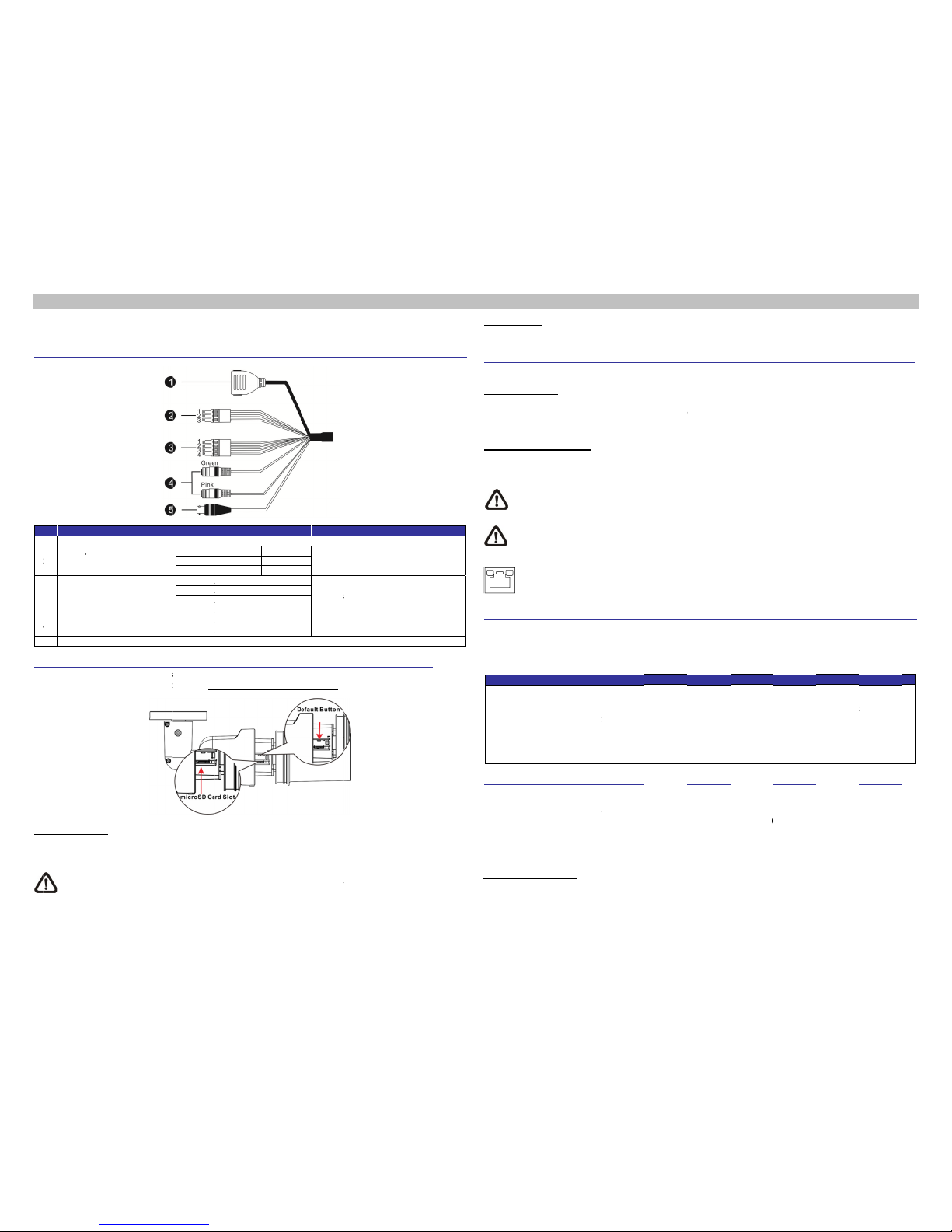
l-in-One
C
o
1 RJ-45
2
Powe
r
(3-pin
3
Alarm
(4-pin
4
Audio
5 BNC
i
croSD C
a
e positions
mera’s fron
t
croSD Car
d
ert the mic
r
mera is po
w
NOTE
suppo
r
inform
f
or quick in
s
er’s Manua
able
Cable
(DC 12V /
A
Ter mi na l B
I/O
Ter mi na l B
I/O
rd Slot /
D
of microS
D
housing, p
l
Slot
oSD card i
n
ered on.
: It is not re
c
r
t long ter
m
ation regar
d
talling and
l of the cam
C 24V)
lock)
lock)
efault B
u
card slot
a
ease refer
t
to the card
c
ommende
d
continuou
ing the reli
a
connecting
era in the s
u
Pin
1
2
3
1
A2 A3 A4 A
Green
A
Pink
A
-
tton
a
nd default
o section m
slot to stor
e
to record
w
s data rea
d
bility and t
h
DIGITUS
D
pplied CD.
Defi
For networ
k
DC 12V −
Reserved
DC 12V +
A
larm In −
A
larm In +
A
larm Out
−
A
larm Out
+
A
udio Out
A
udio In /
M
For analog
v
button are
icroSD Car
d
videos an
d
ith the mic
r
/write. Ple
a
e life expe
c
N-16084-1
nition
and PoE c
o
AC 24V 1
GND
AC 24V 2
ic In
v
ideo outpu
shown as
Slot / Def
a
snapshot
s
r
oSD card f
o
se contact
tancy.
Bullet IP
C
o
nnections
Power
c
Alarm
c
Two- w
a
t
below. For
ult Button i
n
. Do not re
m
r 24/7 con
t
the manu
f
B
amera. Fo
r
Re
m
onnection
onnection
y audio tra
n
details abo
the User’s
ove the m
i
inuously, a
s
acturer of
t
ullet I
P
more deta
i
arks
smission
ut how to
d
Manual.
i
croSD card
it may not
he microS
D
Cam
e
i
ls, please
etach the
when the
be able to
card for
ra Qui
c
Default
B
Press th
e
Camer
a
Please f
o
Power
C
Please
u
power o
u
other en
d
Etherne
t
Connect
cable to
N
P N
c
Before
A client
p
camera,
plug-ins
supplied
A
Step 1
:
Step 2
:
Step 3
:
Step 4
:
Camer
a
The ca
m
camera
c
detected
the cam
e
IP Addr
e
Subnet
M
Login I
D
Key i
n
Enter
case
s
k Guid
Button
e
default bu
Cabling
llow the in
s
onnection
se a DC 1
2
tlet. Altern
a
d
of the ca
b
t Cable Co
n
one end of
the networ
k
OTE: In s
o
C.
OTE: Che
c
heck the L
A
Green Li
Orange
A
Login to
t
program wi
l
please en
s
or setting I
CD.
ctiveX Co
: Start the I
: Select <
T
browser.
T
: Click the
<
and click
settings.
: Set “Acti
v
<Prompt
>
Login
era is def
a
c
an be fou
n
, then the c
a
ra under fi
x
ss: 192.16
8
ask: 255.
2
and Pass
w
the camer
a
the default
u
ensitive.
e
tton with a
p
tructions b
e
V / AC 24
V
tively, con
n
le to a Pow
e
nection
the Ethern
e
switch or
P
me cases,
E
k the stat
u
N connecti
o
nk Light ind
ctivity Ligh
t
he Came
r
l be autom
a
ure downl
o
nternet’s s
e
ntrols and
nternet Exp
ools> from
hen click <
Security> t
<Custom l
e
eX control
s
or <Enabl
e
ult set as
D
d via UPn
P
mera woul
d
ed IP addr
e
.0.100
55.255.0
ord
’s IP addre
s
sername (
a
roper tool
f
low for ca
b
adaptor
a
ect the Et
h
r Sourcing
t cable to t
C.
thernet cr
o
s of the lin
on.
icates good
t
flashes for
ra
tically inst
a
ading the
A
curity level
Plug-ins S
e
lorer (IE).
the main
Internet Op
t
ab and sel
e
vel> to ch
a
and plug
-
>.
HCP mod
e
search or
d switch au
t
ss, please
s
ss in the U
R
dmin) and
o
r at least
2
le connecti
o
nd connect
ernet cable
Equipment
e RJ-45 c
o
ssover cabl
indicator
a
network co
network ac
t
lled to the
ctiveX co
n
to default.
ttings
menu of t
h
ions>.
ct <Internet
>
nge Activ
e
ins” items
t
to obtain
please use
omatically
t
et the IP a
d
L bar of th
e
password (
0 seconds
t
ns.
it to the 3-
to the RJ-
4
(PSE) swit
c
nnector of
t
e might be
n
a
nd the act
nnection.
tivity indica
t
PC when c
trol is allo
w
For further
e
>,
X
to
Step 1:
Step 2:
Step 3:
Step 4:
IP address
the search
o fixed IP a
dress of th
e
web brow
s
admin) in t
h
o restore th
p
in termina
l
5 connect
o
h.
he All-in-O
n
eeded wh
e
i
vity indicat
o
ion.
o
nnecting t
o
ed by eith
e
details, ple
Int
e
Start the I
n
Select <
T
browser.
T
Click the
<
Down the
<OK> to
c
window,
accessing
from the
D
tool from t
h
ddress und
e
PC as: 19
er window
a
e prompt r
e
e system.
l
block of t
h
r of the All
-
e cable, a
n
n connecti
n
r LEDs. If
the came
r
er changin
g
ase refer t
o
ernet Secu
n
ternet Exp
l
ools> from
hen click <
I
Security> t
a
page, clic
k
onfirm the
s
and open
the IP cam
e
HCP serv
e
e CD. Ho
w
r 192.168.
0
2.168.0.XX
X
nd hit on “
E
quest dial
o
e All-in-On
e
in-One cab
l
d plug the
o
g the came
r
the LEDs
a
a. Before l
o
the Activ
e
the User’
s
ity Level
orer (IE).
the main
nternet Opt
b and sele
c
“Default L
e
etting. Clo
s
a new
o
ra.
r. Under D
H
ever if no
D
.250. Ther
e
; for exam
p
nter”.
gue. Note t
h
cable an
d
l
e, and plu
g
ther end o
f
r
a directly t
o
re unlit, pl
e
gging in t
o
X controls
Manual in
menu of
t
ions>.
c
t <Internet
>
vel” and cl
e the brow
s
ne later
CP mode,
D
HCP serv
e
fore, to ac
c
le:
at userna
m
the
the
the
the
ase
the
and
the
he
.
i
ck
er
f
or
the
r is
ess
e is
000B05ZXZ101_Ver1.2
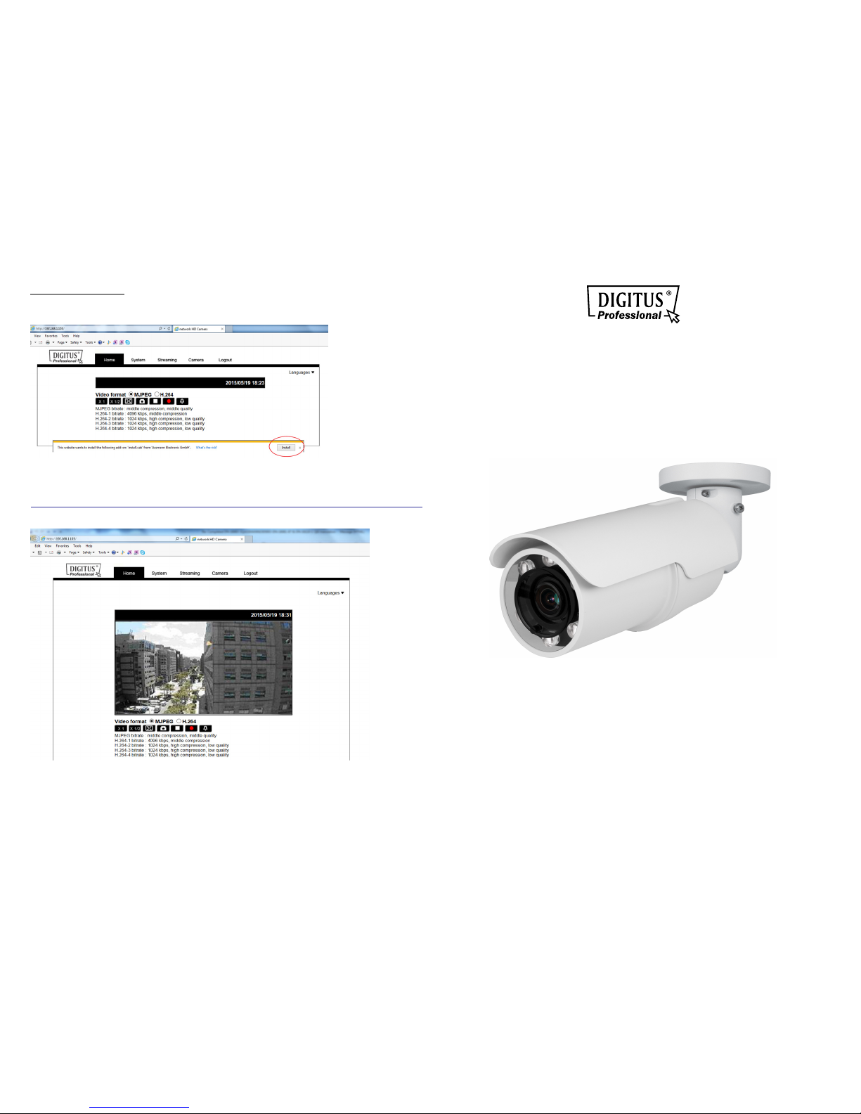
Install the ActiveX Control
After connecting to the camera, the request for installing the ActiveX control will appear just below the URL bar.
Right click on the information bar, and then click on <Install ActiveX Control…> to permit ActiveX control
installation.
In the pop-up security warning window, click on <Install> to start downloading Viewer software on the PC.
Click on <Finish> after Viewer installation is completed.
Browser-based Viewer
The main page of the IP camera user interface is shown as the figure below. Please note that function buttons will
vary depending on the camera model.
IR BULLET IP CAMERA
Quick Installation Guide
DN-16084-1
 Loading...