

User Manual
db Nexus (dbNEXII) - Networked Access Control Solution
db Nexus (dbNEXIII) - Networked Access Control Solution
db Sentry (dbSAI) - Standalone Access Control Solution
db Tracker (dbTRI) - Time and Attendance System

Table of Contents
Initial Setup............................................................................................................................. 3
Using the Unit to Gain Access .................................................................................................... 7
Correct Use of RFID Card/Token................................................................................................. 7
Correct Use of Fingerprint.......................................................................................................... 7
Correct Use of Fingerprint.......................................................................................................... 8
Successful Access .....................................................................................................................9
Error Responses ....................................................................................................................... 9
Entering the Menu after Initial Setup .......................................................................................... 9
Entering the Menu after Initial Setup ........................................................................................ 10
Menu Overview ...................................................................................................................... 10
Menu Layout .......................................................................................................................... 10
Add a User Via the Menus........................................................................................................ 11
Edit a User Via the Menus........................................................................................................ 11
Deleting a User Via the Menus.................................................................................................. 12
Unit Configuration .................................................................................................................. 13
Setting the Unit's Real-time Clock Via the Menus........................................................................ 14
Creating Time Codes Via the Menus .......................................................................................... 14
Setting the IP Address Via the Menus........................................................................................ 16
Appendix 1 - Menu Maps ......................................................................................................... 17
Appendix 2 - Troubleshooting .................................................................................................. 23
Digitus Biometrics, Inc.
User Manual - Models: dbNEXII, dbNEXIII, dbSAI, dbTRI
Page 2 of 27

FCC Notice for db Nexus III
This equipment has been tested and found to comply with the limits for a Class A digital
device, pursuant to part 15 of the FCC Rules. These limits are designed to provide reasonable
protection against harmful interference in a residential installation. This equipment generates,
uses and can radiate radio frequency energy and, if not installed and used in accordance with
the instructions, may cause harmful interference to radio communications. However, there is
no guarantee that interference will not occur in a particular installation. If this equipment does
cause harmful interference to radio or television reception, which can be determined by
turning the equipment off and on, the user is encouraged to try to correct the interference by
one or more of the following measures:
• Reorient or relocate the receiving antenna.
• Increase the separation between the equipment and receiver.
• Connect the equipment into an outlet on a circuit different from that to which the receiver is
connected.
• Consult the dealer or an experienced radio/TV technician for help.
Caution: Any changes or modification cautions to this device not explicitly approved by
manufacturer could void your authority to operate this equipment.
This device complies with part 15 of the FCC Rules. Operation is subject to the following two
conditions: (1) This device may not cause harmful interference, and (2) this device must
accept any interference received, including interference that may cause undesired operation.
Digitus Biometrics, Inc.
User Manual - Models: dbNEXII, dbNEXIII, dbSAI, dbTRI
Page 3 of 27

Initial Setup
› On a new unit, all fingerprint indexes are unused.
› When a new unit is powered up, it will immediately go into the Initial Setup
menu. The menu consists of a number of options that can be selected or
turned on / off, and requires numeric values to be entered using the keypad.
The initial setup of each db Nexus unit is very simple and should only take a couple
of minutes.
When the unit is powered-up, you should see the following on the Head Unit's LCD:
LCD CONTRAST
(0-9):[0] #=DONE
› Using the keypad on the Head Unit enter a value 0 thru 9 to set your
preferred contrast for the LCD display. You will see the contrast change as
each value is selected. If the chosen contrast is not correct, try a different
value until you have the desired contrast.
› Once you have the desired contrast, press the # key.
The next screen on the Head Unit LCD will be:
<Blank Line>
ENTER PASSWORD
› Enter a 16-digit numeric password. This is used for the code hopping
encryption that operates between the Head Unit and Control Unit and also
between the Control Unit and PC software.
Note: This same password must also be entered into the Management
Software, so please make a record of the password before entering it.
› Following the 16th digit being entered, the Head Unit will display the entered
password on the top line of the LCD and display [#]=DONE on the bottom
line. The cursor will move to the # character to allow you to review the
password. If you are certain that the password has been entered correctly
press the # key. If you want to change the password, use the * key as a
back-space to delete the password entered.
Note: This value cannot be re-entered. This is a one-time only process.
The next stage is to optionally enroll 2 managers onto the unit for testing purposes.
The following messages will be displayed on the Head Unit LCD:
ENROLL MANAGERS?
YES=1 NO=0
It is highly recommended that you enroll the 2 managers at the Head Unit for testing
purposes. If you choose not to enroll managers via the Head Unit at this point, the
unit will need to be networked and users enrolled onto the unit via the DAS
Management Software.
Digitus Biometrics, Inc.
User Manual - Models: dbNEXII, dbNEXIII, dbSAI, dbTRI
Page 4 of 27

If you have reached this stage following a firmware upgrade and wish to preserve
the existing enrolled users, it is recommended that you choose NO. If you select NO,
this completes the setup procedure.
If you choose "YES", the following will be displayed.
ENROLL MANAGERS
<1 second delay>
NEW MANAGER
ENTER ID:0001
<1 second delay>
PLACE FINGER
KEY 1 WHEN READY
› Once the finger is placed on the scanner, ensuring that the finger is flat and
straight, press 1 on the Head Unit keypad.
› After about 1 second the Head Unit will display:
PRINT STORED
REMOVE FINGER
› Remove the finger from the fingerprint scanner.
› The Head Unit will then display:
PLACE FINGER
ON SCANNER
› Place the same finger on the scanner to verify the enrollment.
› The Head Unit will then display:
PRINT VERIFIED
REMOVE FINGER
<1 second delay>
NEW MANAGER
ENTER ID:0002
<1 second delay>
PLACE FINGER
KEY 1 WHEN READY
› Once the finger is placed on the scanner, ensuring that the finger is flat and
straight, press 1 on the Head Unit keypad.
Note: You should either use a different finger or preferably a different person
for the 2nd enrolled finger.
› After about 1 second the Head Unit will display:
Digitus Biometrics, Inc.
User Manual - Models: dbNEXII, dbNEXIII, dbSAI, dbTRI
Page 5 of 27

PRINT STORED
REMOVE FINGER
› Remove the finger from the fingerprint scanner.
› The Head Unit will then display:
PLACE FINGER
ON SCANNER
› Place the same finger on the scanner to verify the enrollment.
› The Head Unit will then display:
PRINT VERIFIED
REMOVE FINGER
<1 second delay>
SETUP COMPLETE
<1 second delay>
01/01/01 00:00
ENTER ID:_
The initial setup is now complete!
Note: the date and time will be incorrect. These are set via the PC based
management software
The first enrolled finger is at Index 0001 and the second enrolled finger at
Index 0002.
The unit can be tested by entering the PIN number on the Head Unit keypad and
placing the correct finger on the fingerprint scanner.
The Head Unit LCD will display:
ACCESS GRANTED
Digitus Biometrics, Inc.
User Manual - Models: dbNEXII, dbNEXIII, dbSAI, dbTRI
Page 6 of 27
Using the Unit to Gain Access
All the Digitus Units are configurable as to which credentials are enabled or
disabled.
The dbNEXII, dbSAI and dbTRI have 2 credentials, a PIN number and a
Fingerprint.
The dbNEXIII also has PIN and Fingerprint, but additionally has the RFID
credential.
Which credentials are enabled will determine what is displayed on the LCD.
Credentials are always requested in the same order. The order is:
PIN Number
RFID Card/Token
Fingerprint
The LCD will show a message requesting the first enabled credential will.
If the first enabled credential is PIN, the LCD will display:
07/04/10 2:00PM
ENTER ID: [ ]
If the first enabled credential is RFID, the LCD will display:
07/04/10 2:00PM
PRESENT CARD
If the first enabled credential is Fingerprint, the LCD will display:
07/04/10 2:00PM
PLACE FINGER
Enter or present the first credential, then follow the instructions on the LCD,
presenting each credential as it's requested.
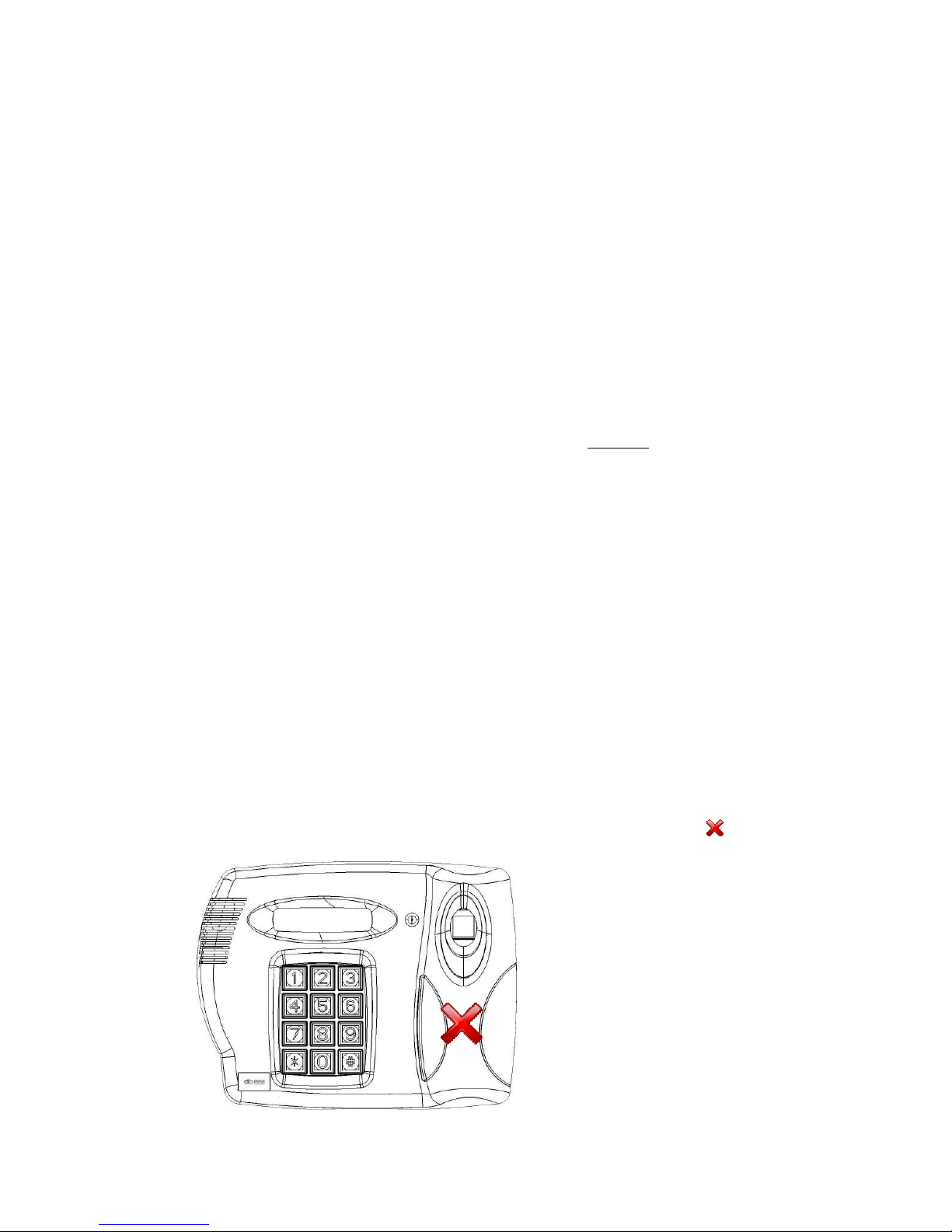
Correct Use of RFID Card/Token
The RFID Card/Token should be help up to the head unit in the position showed
below
Digitus Biometrics, Inc.
User Manual - Models: dbNEXII, dbNEXIII, dbSAI, dbTRI
Page 7 of 27

Correct Use of Fingerprint
Correct placement of the fingerprint is important. Following these simple steps will
ensure that you have a very high percentage success rate when attempting
fingerprint verification or identification.
Place you finger in the opening as shown below (DO NOT SLIDE YOUR FINGER
ALONG THE FINGERPRINT SCANNER)
Place your finger down onto the center of the fingerprint scanner. Do not press down
hard, only apply a slight amount of pressure.
Digitus Biometrics, Inc.
User Manual - Models: dbNEXII, dbNEXIII, dbSAI, dbTRI
Page 8 of 27
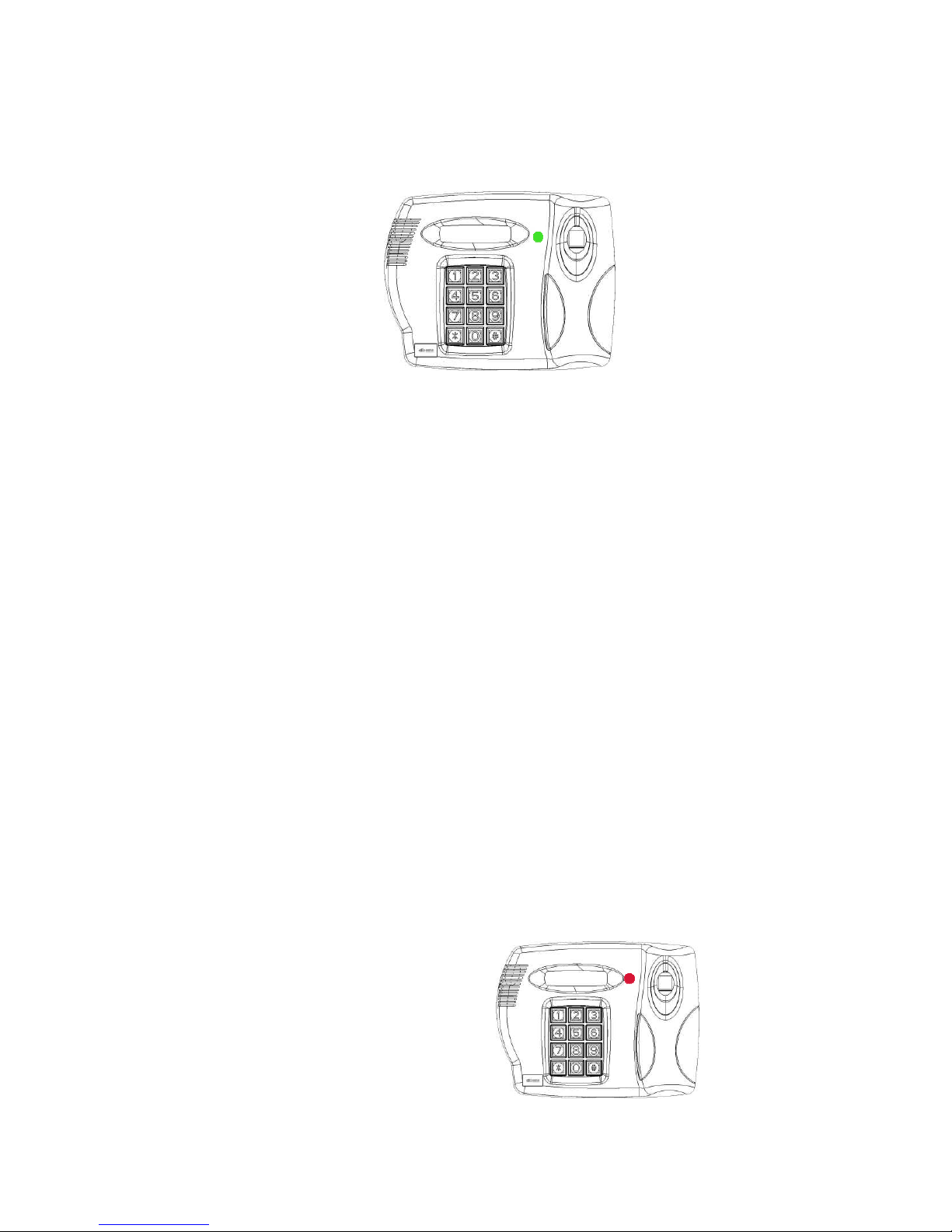
Successful Access
Once all credentials have been presented, a successful Verification or Identification
will be indicated by
07/04/10 2:00PM
ACCESS GRANTED
and displayed on the LCD,
the status LED on the head unit turning green and the door being released.
Error Responses
If the credentials are not verified, you will receive one of the following error
responses:
INVALID ID - No users is enrolled at the Index specified by the PIN number
entered
RFID CARD INVALID - No user is enrolled at the Index specified by the RFID
Card presented
RFID CARD NOT FOUND - No RFID Card/Token was detected
RFID CARD NOT IDENTIFIED - An RFID Card was found but could not be
identified
ACCESS DENIED - The Fingerprint could not be verified
OUTSIDE VALID TIME CODE - All the credentials were verified, but the user is
attempting to gain access outside their permitted times
FINGER NOT FOUND - No finger was detected on the scanner
NO FINGER TEMPLATE FOUND - A user exists at the Index specified, however
no finger templates have been uploaded to the unit for that user
The status LED on the head unit will turn red.
Digitus Biometrics, Inc.
User Manual - Models: dbNEXII, dbNEXIII, dbSAI, dbTRI
Page 9 of 27

Entering the Menu after Initial Setup
Other than at initial setup, the menus can be accessed by any enrolled manager in
the following way:
› Press and release the # key.
› Present the first enabled credential, PIN, RFID Card/Token or Fingerprint.
› Present each additional credential as requested.
The db Nexus and db Tracker units have a comprehensive series of on-board menus.
The entire range of menu options that are available on the db Sentry unit are also
available on the db Nexus and db Tracker units.
It is recommended that most configuration and user enrollment for the db Nexus is
done via the DAS Management Software and not using the menus. The one
exception to this is setting the IP address of the db Nexus unit. To set the IP address
of the db Nexus unit, follow the steps in Setting the IP Address Via the Menus.
Menu Overview
Diagrams of the menus can be found in Appendix 1.
The menus are very intuitive and easy to follow. If a menu item is asking for
a value to be entered, it will show you the range of acceptable values.
If a decision need to be made in the menus, 1=Yes and 0=No is the rule to
follow. Again, this will be displayed on the unit's LCD.
If you see an item that is enclosed in [] (square parentheses), this indicates
the currently selected setting. To retain the current setting, you can press the
# key. For example if the YES option is selected the display would show the
square brackets as such [YES=1].
If you ever need to go back to a previous menu item or back-space or exit a
menu, the * key can be used.
Menu Layout
The menus are broken down into 4 top level menu categories:
› User Menu - Add, Edit and Delete Users.
› Operations Menu - Unit settings. Turn any feature on or off via this menu.
› Time Menu - Set the unit's date and time. Create Time Codes.
› Network Menu - Set the unit's network settings
Digitus Biometrics, Inc.
User Manual - Models: dbNEXII, dbNEXIII, dbSAI, dbTRI
Page 10 of 27

Add a User Via the Menus
NOTE. BEFORE YOU ADD USERS, IF YOU ARE GOING TO WANT TO RESTRICT THE
PERMITTED TIMES A USER WILL HAVE ACCESS, YOU FIRST NEED TO GO INTO THE
TIME MNEY AND SETUP TIME CODES.
After you enter the menus, you will see the following displayed on the Head Unit's
LCD:
User Menu?
Yes=1 No=0
Press the 1 (one) key. You will now see the following displayed:
Add User
Enter ID [ ]
Enter a 4-digit PIN number to be assigned to the new user.
Follow the instructions on the LCD to enroll the user's first fingerprint.
Select the user type:
Manager=1
Super User=2
User=3
"Managers" and "Super Users" have access to the unit's menus. "Users" don't have
access to the menus. MOST PEOPLE WILL BE ENROLLED AS A USER.
Follow the instructions to enroll additional fingerprints for the user. IT IS
RECOMMENEDED THAT AT LEAST 1 FINGER FROM EACH HAND BE ENROLLED.
Follow the instructions to enroll up to 2 Duress Fingers. If a user is being forced to
place their finger on a unit to open a door, they can use a duress finger to trigger an
alert that they are entering under duress. For db Nexus and db Tracker systems, the
alerts will get sent to the DAS software. For all units, there is an alarm relay that is
activated following a duress entry. The contacts of the alarm relay can be connected
to any 3rd-party system, to send notification of the alarm.
Specify the 2-digit Time Code (00-99) to apply to the user. The Time Codes are
setup via the Time Menu.
Choose to save the user when prompted.
Edit a User Via the Menus
Editing a user is almost identical to Adding a User.
User Menu?
Yes=1 No=0
Press the 1 (one) key until you see the following displayed:
Add User
Enter ID [ ]
Press the 0 (zero) key until you see the following displayed:
Digitus Biometrics, Inc.
User Manual - Models: dbNEXII, dbNEXIII, dbSAI, dbTRI
Page 11 of 27

Edit User
Enter ID [ ]
Press the 1 (one) key. Follow the instructions on the LCD to edit the user.
Deleting a User Via the Menus
After you enter the menus, you will see the following displayed on the Head Unit's
LCD:
User Menu?
Yes=1 No=0
Press the 1 (one) key until you see the following displayed:
Add User
Enter ID [ ]
Press the 0 (zero) key until you see the following displayed:
Delete User
Enter ID [ ]
Enter a 4-digit PIN number of the user to be deleted.
The user is now deleted.
Digitus Biometrics, Inc.
User Manual - Models: dbNEXII, dbNEXIII, dbSAI, dbTRI
Page 12 of 27

Unit Configuration
Any settings that are specific to the unit can be set via the Operations Menu.
User Menu?
Yes=1 No=0
Press the 0 (zero) key, you see the following displayed:
Operations Menu?
Yes=1 No=0
Press the 1 (one) key. Follow the instructions to set the various options for the unit:
› LCD Contrast (0-9) - Use the number keys 0 thru 9 to change the LCD
contrast. As you press a key you will see the contrast change. Press the #
key when you are happy with the setting
› Enter Delay? (1-9 SEC) - Use the number keys 1 thru 9 to change the entry
delay. The entry delay is the number of seconds the doors will open for
following a successful access.
› Exit Delay? (1-9 SEC) - Use the number keys 1 thru 9 to change the exit
delay. The exit delay is the number of seconds the doors will open for
following a Request To Exit (RTE) button being pressed.
› Propped Door Alarm - Press 1 to turn this feature ON or 0 to turn this feature
OFF. The propped door delay requires door contacts to be installed. If this
feature is turned ON, you will be prompted to enter the Propped Door Delay
next.
› Propped Door Delay (1-99 MIN) - Use the number keys entering values 1 thru
99 to change the delay period. This is the number of minutes the door can be
propped open before creating an alarm.
› Security Level? (1-3) - Use the number keys 1 thru 3 to change the security
level. Level 2 is the default level. Level 1 is most tolerant to different finger
placement. Level 3 is the most secure and will require most accurate finger
placement on the fingerprint scanner.
› Set Credentials - The default credentials for all units are PIN and Fingerprint
enabled. The db NEXIII also has an RFID reader incorporated into the unit.
RFID is turned OFF by default. Select 1 to change which credentials are
enabled, select 0 to retain the current settings.
› If you chose to modify the credential settings you will be prompted to turn on
or off each of the 3 credentials. Press 1 to enable a credential or 0 to disable
it.
› Press 1 when prompted to save the new configuration data.
Digitus Biometrics, Inc.
User Manual - Models: dbNEXII, dbNEXIII, dbSAI, dbTRI
Page 13 of 27

Setting the Unit's Real-time Clock Via the Menus
After you enter the menus, you will see the following displayed on the Head Unit's
LCD:
User Menu?
Yes=1 No=0
Press the 0 (zero) key until you see the following displayed:
Time Menu?
Yes=1 No=0
Press the 1 (one) key. You will now see the following displayed:
Set Time & Date?
Yes=1 No=0
Press the 1 (one) key.
Enter the Time & Date as requested.
Choose to Save the new Time & Date when prompted.
Creating Time Codes Via the Menus
After you enter the menus, you will see the following displayed on the Head Unit's
LCD:
User Menu?
Yes=1 No=0
Press the 0 (zero) key until you see the following displayed:
Time Menu?
Yes=1 No=0
Press the 0 (zero) key. You will now see the following displayed:
Set Time Codes?
Yes=1 No=0
Press the 1 (one) key. You will now see the following displayed:
Enter Time Code:
(01-99): ____
Enter the time code number you want to create or edit, valid entries are 01 thru 99.
You will then be prompted to enter the 1st Time Code for Sunday.
1st Time Code:
SUN: HH:MM-HH:MM
Digitus Biometrics, Inc.
User Manual - Models: dbNEXII, dbNEXIII, dbSAI, dbTRI
Page 14 of 27

Each day allows for up to 2 non-contiguous blocks of time to be entered for each
day. If only a single block of time is required for a given day, leave the 2nd Time
Code set to 00:00-00:00.
Note that times are entered using 24hr clock format.
Note: you can use the # key to step through any section without making changes.
Example 1 - Single Block of time for a given day
If you want to allow access between the hours of 9:00am to 5:00pm, enter data as
follows:
1st Time Code:
SUN: 09:00:-17:00
2nd Time Code:
SUN: 00:00-00:00
Example 2 - Two Blocks of time for a given day
If you have cleaning crews who are allowed access only between the hours of
6:00am to 8:00am and 8:00pm to 10:00pm, enter data as follows:
1st Time Code:
SUN: 06:00:-08:00
2nd Time Code:
SUN: 20:00-22:00
After entering the times for Sunday you will be prompted with the following:
Make MON Same?
Yes=1 No=0
If you want Monday to have the same times as Sunday press 1. If you want to enter
different times for Monday press 0. If you press 0, enter the times for Monday, in
exactly the same format as Sunday. If you choose 1 you will be asked if you want
Tuesday to have the same time as Monday. This process repeats until you have
completed the access times thru Saturday.
Once all time have been entered, you will be prompted:
Save Time Code?
Yes=1 No=0
Press the 1 (one) key to save the time code.
Digitus Biometrics, Inc.
User Manual - Models: dbNEXII, dbNEXIII, dbSAI, dbTRI
Page 15 of 27

Setting the IP Address Via the Menus
After you enter the menus, you will see the following displayed on the Head Unit's
LCD:
User Menu?
Yes=1 No=0
Press the 0 (zero) key until you see the following displayed:
Network Menu?
Yes=1 No=0
Press the 1 (one) key. You will now see the following displayed:
Network Config?
Yes=1 No=0
Press the 1 (one) key. You will now see the following displayed:
Use DHCP?
Yes=1 No=0
If you have a DHCP on your network that will automatically assign the unit an IP
address, select 1. The unit will then wait for up to 1 minute for the IP address to be
assigned.
If you do not have a DHCP server, or would like to specify a static IP address, select
0. You will be prompted to enter the IP Address, Subnet Mask and Default Gateway:
Enter IP Address
_ _ _._ _ _._ _ _._ _ _
Note each section of the address must be entered as a 3-digit number, e.g. to enter
10.0.0.1 you need to enter 010.000.000.001.
Once you have entered the IP Address, Subnet Mask and Default Gateway you will
be see the following:
Save Settings?
Yes=1 No=0
Click 1 to save the IP settings.
Digitus Biometrics, Inc.
User Manual - Models: dbNEXII, dbNEXIII, dbSAI, dbTRI
Page 16 of 27

Appendix 1 - Menu Maps
Digitus Biometrics, Inc.
User Manual - Models: dbNEXII, dbNEXIII, dbSAI, dbTRI
Page 17 of 27

Digitus Biometrics, Inc.
User Manual - Models: dbNEXII, dbNEXIII, dbSAI, dbTRI
Page 18 of 27

Digitus Biometrics, Inc.
User Manual - Models: dbNEXII, dbNEXIII, dbSAI, dbTRI
Page 19 of 27

Digitus Biometrics, Inc.
User Manual - Models: dbNEXII, dbNEXIII, dbSAI, dbTRI
Page 20 of 27

Digitus Biometrics, Inc.
User Manual - Models: dbNEXII, dbNEXIII, dbSAI, dbTRI
Page 21 of 27

Digitus Biometrics, Inc.
User Manual - Models: dbNEXII, dbNEXIII, dbSAI, dbTRI
Page 22 of 27

Appendix 2 - Troubleshooting
Head Unit Problems
Problem
The following message is displayed on the Head Unit LCD:
BASE STATUS:
CANNOT CONNECT
Solution
There is a communication problem between the Head Unit and Control Unit. The
most common cause of this is a cabling problem. Check the cable that connects the
Head and Control Units together. Ensure the cable is wired "straight-thru", i.e.
Terminal A on the Head is connected to terminal A on the Control Unit, terminal B is
connected to terminal B, etc.
---------------------------/---------------------------
Problem
The following message is displayed on the Head Unit LCD:
CONFIG STATUS:
FAILED
Solution
Power the unit down and back up. If after powering the unit back up, the same
message is displayed, contact your vendor for support.
---------------------------/---------------------------
Problem
The following message is displayed on the Head Unit LCD:
SCANNER STATUS:
INIT. FAILED
followed by
SCANNER STATUS:
'#' TO CONTINUE
Solution
There is a problem with the Head Unit microcontroller communicating with the
Fingerprint Scanner. It's possible that the cable inside the Head Unit that connects
the main PCB to the Fingerprint Scanner was disturbed during installation. The cable
should be attached to the connector located at the bottom left of the main PCB inside
the Head Unit and is labeled "Sensor". Power the unit down and check this cable is
properly seated at both ends.
Digitus Biometrics, Inc.
User Manual - Models: dbNEXII, dbNEXIII, dbSAI, dbTRI
Page 23 of 27

If after powering the unit back up, the same message is displayed, contact your
vendor for support.
---------------------------/---------------------------
Problem
The following message is displayed on the Head Unit LCD:
FLASH STATUS:
FAILED
Solution
Power the unit down and back up. If after powering the unit back up, the same
message is displayed, contact your vendor for support.
---------------------------/---------------------------
Problem
The following message is displayed on the Head Unit LCD:
RFID STATUS:
INIT. FAILED
Solution
If you have purchased a unit that only has a Fingerprint Scanner and Keypad
installed, with no RFID module, this message is normal.
If you have purchased a unit with RFID, there is a problem with the Head Unit
microcontroller communicating with the RFID Module. It's possible that the cable
inside the Head Unit that connects the main PCB to the RFID Module was disturbed
during installation. The cable should be attached to the connector located at the left
edge of the main PCB inside the Head Unit and is labeled "RFID". Power the unit
down and check this cable is properly seated at both ends.
If after powering the unit back up, the same message is displayed, contact your
vendor for support.
---------------------------/---------------------------
Problem
When the unit is powered up for the first time, the LCD display is blank.
Solution
Try pressing 0 (zero) on the Head Unit keypad. The contrast may have been set very
low, making the characters invisible.
---------------------------/---------------------------
Problem
The Control Unit powers up but the Head Unit does not.
Digitus Biometrics, Inc.
User Manual - Models: dbNEXII, dbNEXIII, dbSAI, dbTRI
Page 24 of 27

Solution
There may be a wiring problem between the Head Unit and Control Unit. Check the
cable that connects the Head and Control Units together. Ensure the cable is wired
"straight-thru", i.e. Terminal A on the Head is connected to terminal A on the Control
Unit, terminal B is connected to terminal B, etc. The 2 wires that supply power are
terminals A and B.
There is fuse between the Control Unit and Base Unit. The fuse may have blown.
Remove the fuse from the fuse holder, located on the main PCB inside the Control
Unit. The fuse is labeled "HEAD 1A-FAST". Check the fuse with a Ohm Meter to see if
it has blown. Replace the fuse with a 1Amp Fast Blow Fuse if necessary.
If neither of these solutions solve the problem, contact your vendor for support.
Control Unit Problems
Problem
The Control Unit does not power up.
Solution
The external power-supply may be bad. Using a Volt Meter, check the input voltage
on terminals V- and V+ on the POWER connector is the Control Unit. If you are not
seeing the specified voltage output of the power supply, the power supply needs
replacing.
If the input voltage is correct, the input fuse may have blown. Remove the fuse from
the fuse holder, located on the main PCB inside the Control Unit. The fuse is labeled
"BASE 2A-SLO BLO". Check the fuse with a Ohm Meter to see if it has blown. Replace
the fuse with a 2Amp Slow Blow Fuse if necessary.
---------------------------/---------------------------
Problem
When you power the Control Unit up you hear a constant clicking sound from a relay
inside the Control Unit..
Solution
Immediately power the Control Unit down and check that the battery cables have not
been reversed. The Positive side of the battery (RED in color) should be connected to
the B+ terminal on the POWER connector. The Negative side of the battery (BLACK
in color) should be connected to the B- terminal on the POWER connector.
If the battery is wired incorrectly, correct the problem and power the Control Unit up
again. Depending on how long the unit was powered up with the battery cables being
reversed, permanent damage may have occurred to the Control Unit and/or battery.
If the Control Unit will not power up, even after changing the input fuse, contact
your vendor for support.
---------------------------/---------------------------
Digitus Biometrics, Inc.
User Manual - Models: dbNEXII, dbNEXIII, dbSAI, dbTRI
Page 25 of 27

Problem
When you power the Control Unit up you hear the buzzer sound for 1 second, the
buzzer turns off and them immediately turns back on and stays on.
Solution
One of 3 conditions can cause this:
1.) The Tamper Circuit on the Head Unit is open. This can be because the switch
inside the Head Unit isn't properly closed, or because there is a wiring problem
between the Control Unit and the Head Unit.
Check the Head Unit is correctly screwed together.
Check the switch lever on the PCB inside the Head Unit (labeled SW1) isn't
damaged.
Check that the cable connecting the Head Unit to the Control Unit isn't interfering
with the switch lever.
There may be a wiring problem between the Head Unit and Control Unit. Check
the cable that connects the Head and Control Units together. Ensure the cable is
wired "straight-thru", i.e. Terminal A on the Head is connected to terminal A on
the Control Unit, terminal B is connected to terminal B, etc. The 2 wires that are
used for the tamper circuit are terminals G and H.
2.) The Door Sensor Circuit is open.
Refer to the Door Sensor section of the Installation Manual.
Ensure that the Jumpers are set correctly, according to the type of sensor being
used.
If a door sensor is not being used, ensure that the Door Sensor inputs (labeled
OPEN and GND) on the DOOR connector are connected together (refer to
Installation Manual).
3.) The Normally Closed Fire Circuit is open.
Refer to the Fire Panel Integration section of the Installation Manual.
If a normally closed fire circuit is not being used, ensure that the terminals
labeled GND and NC on the FIRE connector are connected together (refer to
Installation Manual).
---------------------------/---------------------------
Problem
When you power the Control Unit up you hear the door relay click open and stay
open.
Digitus Biometrics, Inc.
User Manual - Models: dbNEXII, dbNEXIII, dbSAI, dbTRI
Page 26 of 27

Solution
The jumper on the Control Unit PCB is set incorrectly or is missing. Refer to the Door
Sensor section of the Installation Manual for correct configuration of the jumper.
---------------------------/---------------------------
Problem
Following the initialization sequence, where the status LED (labeled STATUS) turns
green for 1 second, then toggles between yellow and green several time, the status
LED turns yellow and stays yellow.
Solution
The Control Unit logs are corrupt and must be wiped clean. Please contact your
vendor for support.
---------------------------/---------------------------
Problem
After entering a password on the Head Unit, as described in the Initial Setup section
of this manual, the status LED turns red and stays red.
Solution
The Head Unit is attempting to send a password to the Control Unit, when the
Control Unit already has a password. The microprocessor in both the Head Unit and
Control Unit need to be replaced. Please contact your vendor for support.
---------------------------/---------------------------
Problem
The status LED turns red for up to 1 minute then returns back to green.
Solution
A "Clear All Logs" command has be issued to the unit via the network software. This
is a normal operation and no user intervention is required.
Digitus Biometrics, Inc.
User Manual - Models: dbNEXII, dbNEXIII, dbSAI, dbTRI
Digitus Biometrics, Inc.
116A East Oglethorpe Avenue
Savannah, GA 31401 USA
Phone: 912-231-8175
Fax: 912-344-4548
www.digitus-biometrics.com
support@digitus-biometrics.com
Page 27 of 27
 Loading...