

Page 1
db ServerRack V2 (Zero-U)
Installation Manual
Page 2

Table of Contents
Determining which Lock Pawl to use ................................................................................................ 3
Mounting the Door Interface Box ................................................................................................... 5
Mounting the Door Interface Box - Step 1 ......................................................................................... 5
Mounting the Door Interface Box – Step 2 ......................................................................................... 6
Mounting the Door Interface Box – Step 3 ......................................................................................... 7
Mounting the Door Interface Box - Step 4 ......................................................................................... 8
Mounting the Door Interface Box - Step 5 ......................................................................................... 9
Mount the Tie Down Pads to the Door and Cabinet ............................................................................ 10
Connect the CAT5 Cable to the Control Unit ..................................................................................... 12
Installing the Pawl on the Door Lock .............................................................................................. 14
Using the Tamper Switch Inputs ................................................................................................... 15
Using the Door Contact Inputs ..................................................................................................... 17
Using the Alarm Output ............................................................................................................ 19
Using the Wiegand Output ......................................................................................................... 20
Using the Door 2 Output ........................................................................................................... 21
Install the 2
nd
BioLock (Option I) ................................................................................................... 21
Install the Electro-Mechanical Lock (Option II) ................................................................................... 21
Connecting Power to the Control Unit ............................................................................................ 23
Model: db ServerRack V2 Zero-U Digitus Biometrics, Inc. 2011
Page 2 of 24
Page 3
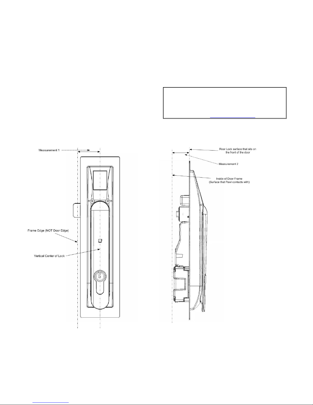
Determining which Lock Pawl to use
A
• As all cabinets vary, we offer a wide range to pawls to suit the particular dimensions of your cabinet.
• There are 2 simple measurements that need to be taken to determine which pawl you will need.
• Please obtain the measurements as show in Figure 1 and Figure 2 and contact our electromechanical lock support
team as show below:
Southco Global Corporate Headquarters
Customer Service & Technical Support Ctr.
Concordville, PA – US
Tel: (610) 459-4000
Email: info@southco.com
Figure 1 Figure 2
Model: db ServerRack V2 Zero-U Digitus Biometrics, Inc. 2011
Page 3 of 24
Page 4
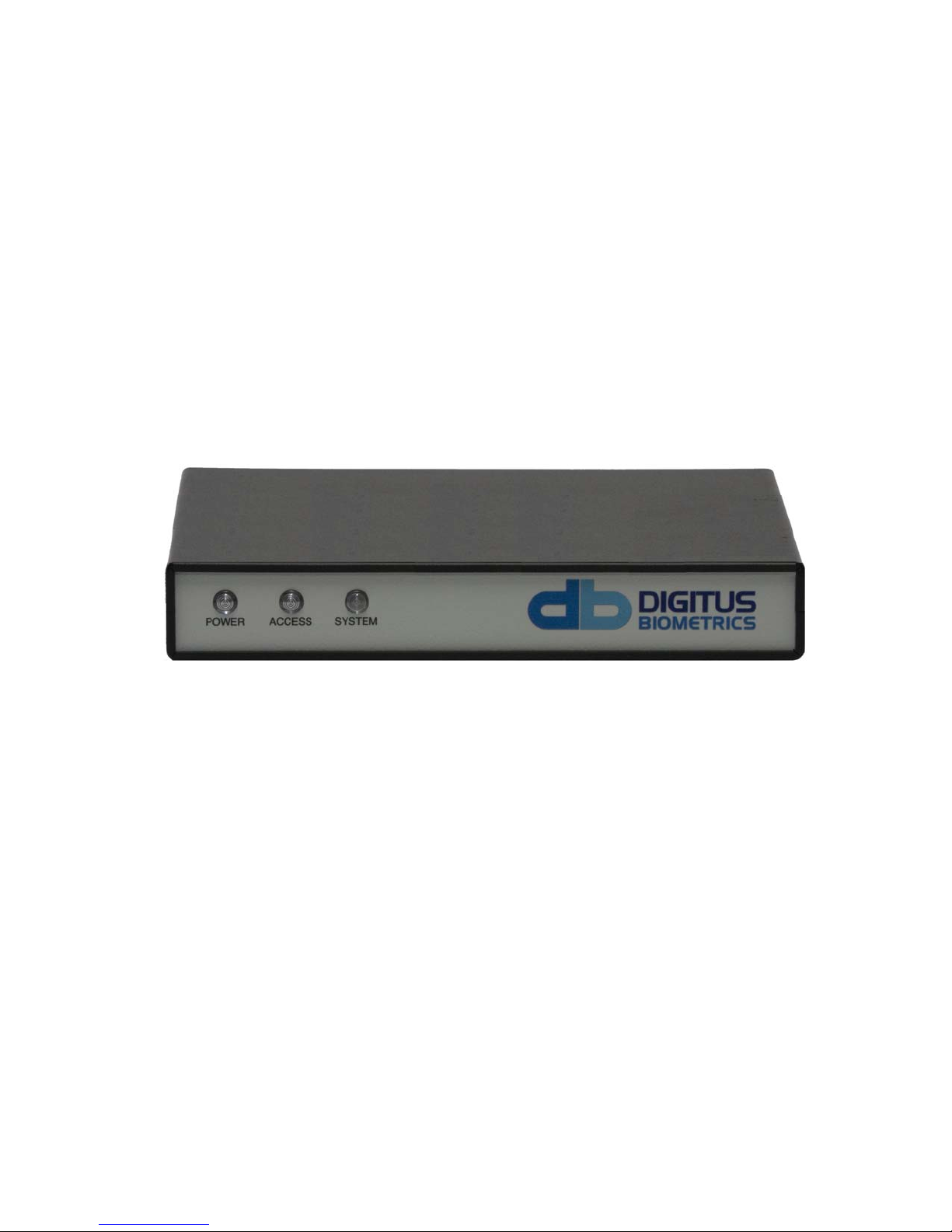
Mounting the Control Unit
• Mount the db ServerRack v2 Zero-U Control Unit
o The Control Unit can be attached using the Magnetic Strips for Steel Cabinets or VHB Strips for Aluminum
Cabinets.
o Alternatively, the Control Unit can be placed on a cabinet shelf
• It is preferable to mount the Control Unit near the top of the rack, to ease the running of cables, however this isn't
absolutely necessary.
Figure 3
Model: db ServerRack V2 Zero-U Digitus Biometrics, Inc. 2011
Page 4 of 24
Page 5
Mounting the Door Interface Box
• If you are installing the db ServerRack Access Control unit to a cabinet that already has a lock installed, remove the
existing lock at this time.
• The "Door Interface Box" provides an interface between the Control Unit and the fingerprint scanner. It also provides
all power and signal connections to the electric lock.
• Install the Door Interface Box as show in Figures 4 thru 9.
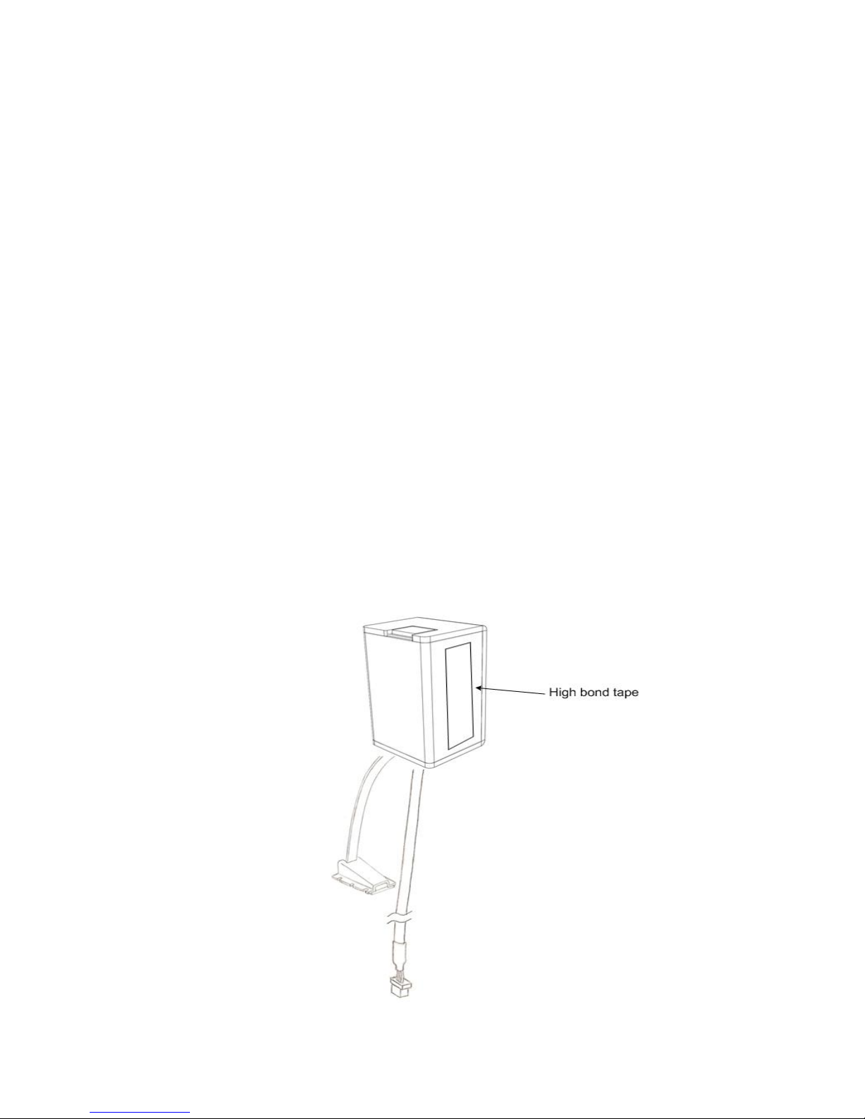
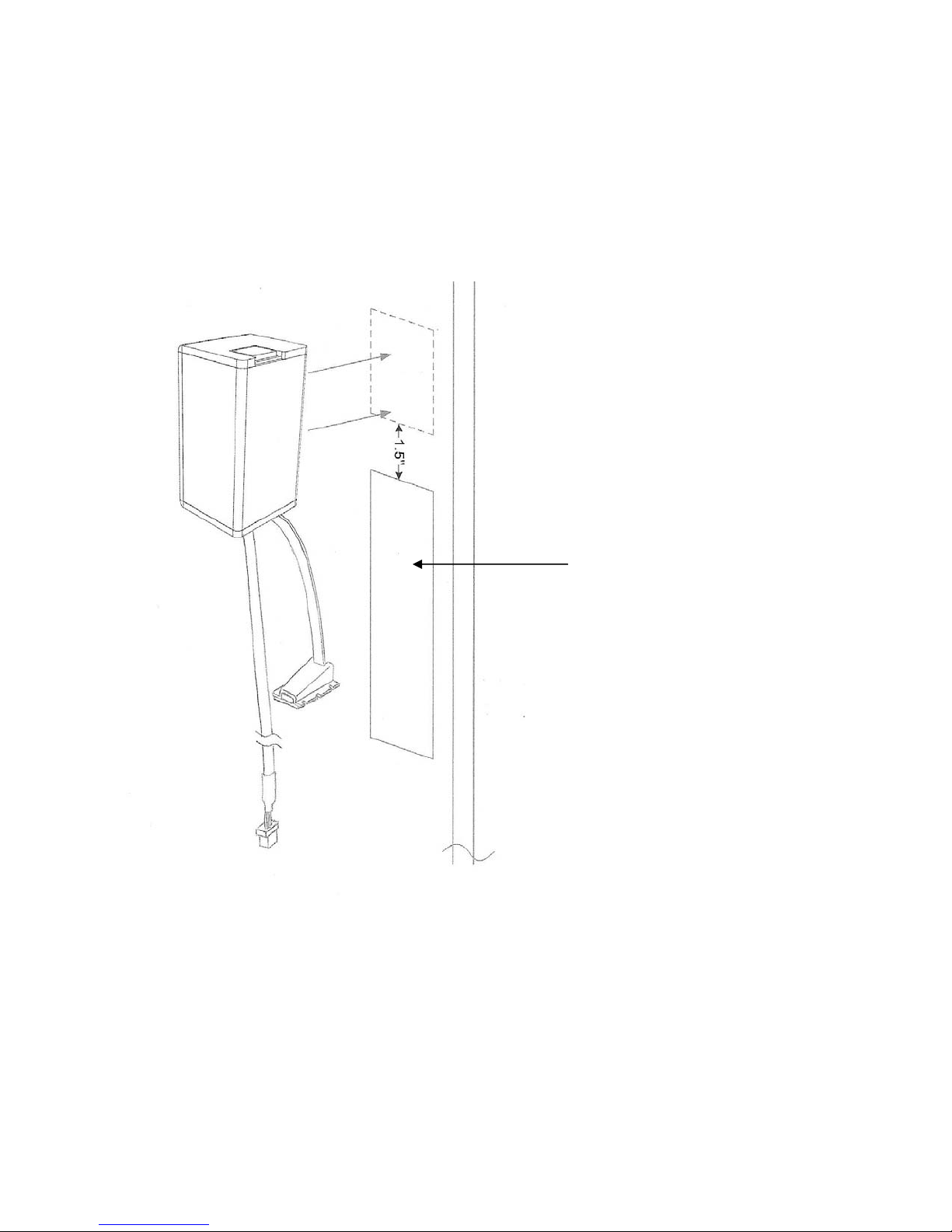
Mounting the Door Interface Box - Step 1
• Before removing the double-sided high bond tape from the Door Interface Box, find a suitable location on the inside
of the cabinet door to mount Interface Box.
• Ensure that the selected location will not affect the cabinet door from closing correctly.
• Note that for glass paneled cabinet doors with very narrow frames, the only suitable location may be on the glass.
IMPORTANT:
• Ensure that the Interface Box is located close enough to the lock opening in the door, so that the finger-
sensor on the ribbon cable can go through the door and connect into the lock, see Figure 6.
• Once you have found a suitable location where you intend to mount the Door Interface Box, ensure that the door
surface is clean and free from any debris. (Using neat alcohol to clean the surface is highly recommended. Allow
drying time before proceeding.)
• Remove the protective cover from the double-sided high bond tape located along the edge of the Door Interface
Box.
Figure 4
Model: db ServerRack V2 Zero-U Digitus Biometrics, Inc. 2011
Page 5 of 24
Page 6
Mounting the Door Interface Box – Step 2
• Attach the Door Interface Box to the inside door surface. Only apply a slight amount of pressure to the high bond
tape until you have ensured that the Door Interface Box will not prevent the cabinet door from closing.
• Once you have ensured that the door will close properly and the finger sensor can attach to the lock, apply more
pressure to the high bond tape. The more pressure applied, the greater the bond.
Figure 5
IMPORTANT:
Ensure that the Interface Box is located
close enough tothe lock openingin the
door, so that the finger-sensor on the
ribbon cable can go through the door
andconnectintothelock,seeFigure6.
* Open slot for lock. 25mm x 150mm (typical)
Model: db ServerRack V2 Zero-U Digitus Biometrics, Inc. 2011
Page 6 of 24
Page 7
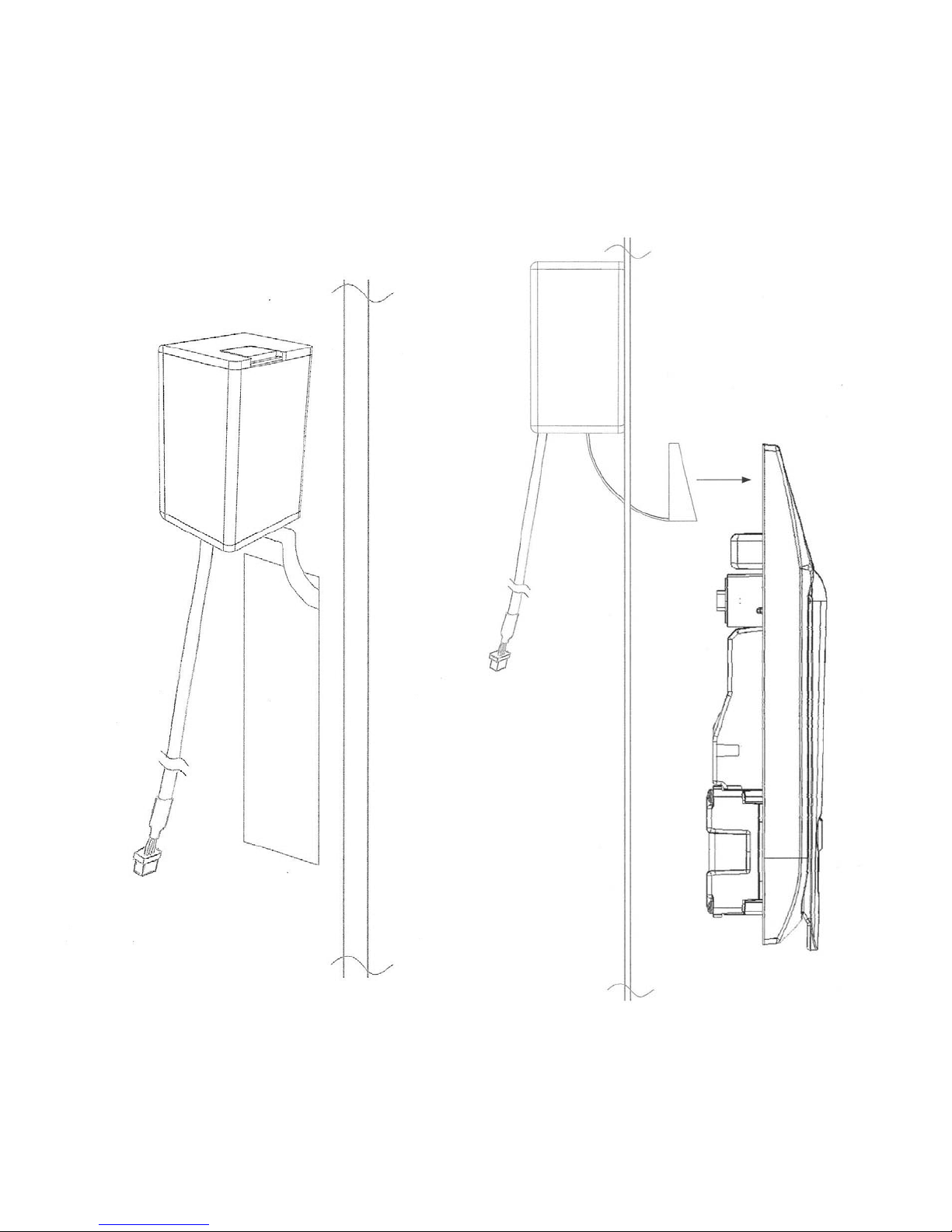
Mounting the Door Interface Box – Step 3
• Push the finger-sensor assembly through the door lock opening as shown in Figure 6.
• Attach the finger-sensor assembly into the back of the door lock as show in Figure 7. Ensure that the angle of the
finger-sensor assembly and the angle of the door lock are as shown in Figure 7.
Figure 6 Figure 7
Model: db ServerRack V2 Zero-U Digitus Biometrics, Inc. 2011
Page 7 of 24
Page 8
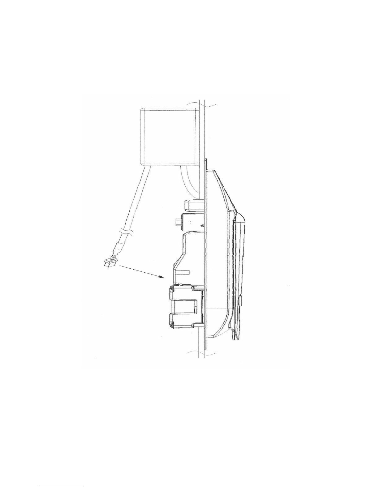
Mounting the Door Interface Box - Step 4
• Situate the lock on the outside of the cabinet door, so that the ribbon cable attached to the finger-sensor assembly
is at the top of the locking opening. (See Figure 8)
Figure 8
Model: db ServerRack V2 Zero-U Digitus Biometrics, Inc. 2011
Page 8 of 24
Page 9
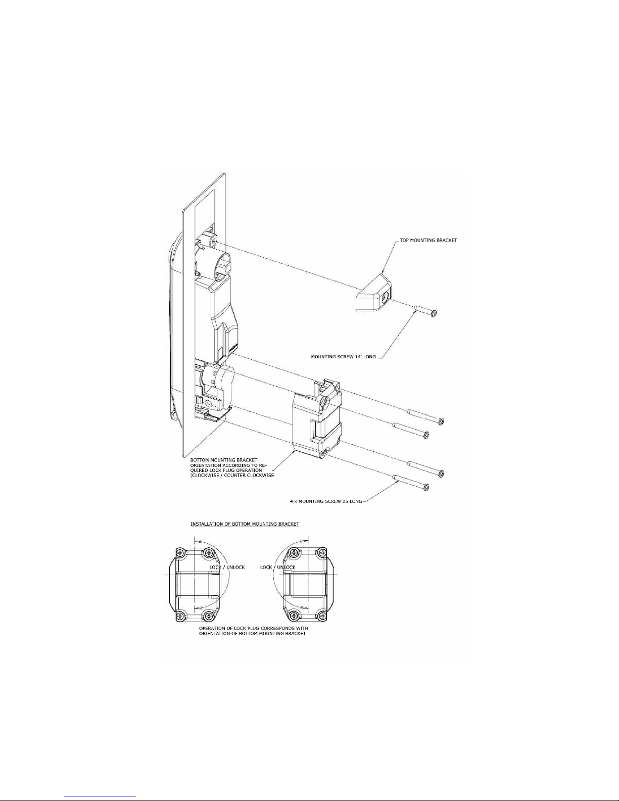
Mounting the Door Interface Box - Step 5
• Secure the lock to the door using the Top Mounting Bracket and Bottom Mounting Bracket as show in Figure 9. Do
not over-tighten the screws in the Bottom Mounting Bracket as this may jam the lock mechanism.
• Attach the lock wire coming out of the Door Interface Box to the back of the lock as shown in Figure 8. The wire will
only plug in one way.
Figure 9
Model: db ServerRack V2 Zero-U Digitus Biometrics, Inc. 2011
Page 9 of 24
Page 10

Mount the Tie Down Pads to the Door and Cabinet
• The Tie Down Pads are used to secure the CAT5 cable that connects the
• Ensure that the door surface is clean and free from any debris. (Using neat alcohol to clean the surface is highly
recommended. Allow drying time before proceeding.)
• Remove the protective cover from each Tie Down Pad and situate as shown in Figure 10.
Door Interface Box to the Control Unit.
Model: db ServerRack V2 Zero-U Digitus Biometrics, Inc. 2011
Figure 10
Page 10 of 24
Page 11

Route the CAT5 Cable between Door Interface Box and the Control Unit.
• Route the supplied CAT5 cable as show in Figure 11. Secure the CAT5 cable to the Tie Down Pads using the supplied
cable-ties.
• Connect the CAT5 cable to the Door Interface Box
Model: db ServerRack V2 Zero-U Digitus Biometrics, Inc. 2011
Figure 11
Page 11 of 24
Page 12

Connect the CAT5 Cable to the Control Unit
• Connect the CAT5 cable to the port labeled "DOOR 1" on the back of the Control Unit as shown in Figure 12.
DO NOT CONNECT THE "DOOR INTERFACE BOX" CABLE TO THE PORT LABELED "NETWORK"
Figure 12
Model: db ServerRack V2 Zero-U Digitus Biometrics, Inc. 2011
Page 12 of 24
Page 13

Connect the Control Unit to a Network
• Use the other supplied CAT5 cable to connect the Control Unit to a Network. Connect the CAT5 cable to the port
labeled "NETWORK" on the back of the Control Unit as shown in Figure 13.
DO NOT CONNECT THE "NETWORK" CABLE TO THE PORTS LABELED "DOOR 1" OR "DOOR 2"
Figure 13
Model: db ServerRack V2 Zero-U Digitus Biometrics, Inc. 2011
Page 13 of 24
Page 14

Installing the Pawl on the Door Lock
• Page 3 of this document describes how to determine which pawl you will need, depending on the make and model
of cabinet. (For help with the lock, see Southco contact information on pg. 3)
• The pawl is installed as shown in Figure 14. Pay particular attention to the Rotation Limiter. This is installed as shown
depending on whether you have a right on left hand opening door.
Model: db ServerRack V2 Zero-U Digitus Biometrics, Inc. 2011
Figure 14
Page 14 of 24
Page 15

Using the Tamper Switch Inputs
• The db ServerRack Access Control unit provides for up to 4 tamper switches. The tamper switches can be connected
to the cabinet side, floor or roof panels. Tamper switches are not included in the kit.
* Tamper switches can be ordered from your db ServerRack Access Control supplier.
DO NOT USE ORDINARY REED SWITCHES AS THESE WILL CAUSE THE PRODUCT TO GO INTO A CONTINUOUS
ALARM CONDITION.
• Pins 1 thru 8 are used for the Tamper Switches, as show in Figures 15a and 15b.
Figure 15a
Figure 15b
• Tamper Switches are connected to any of the following pair of connector pins, 1 & 2, 3 & 4, 5 & 6 or 7 & 8.
• If any of the Tamper Switches are not being used, that pair of connectors must be connected with one of the supplied
terminating resistors. Please wire resistors as show in figure 15c so as to avoid any or the resistor leads touching.
IF ANY RESISTOR LEADS TOUCH, THIS WILL CREATE AN ALARM CONDITION.
• To use one of the Tamper Switched follow the example show in Figure 16. The example connects to pins 1 & 2,
additional Tamper connected Switched can be to any of the remaining pairs of pins.
Model: db ServerRack V2 Zero-U Digitus Biometrics, Inc. 2011
Figure 15c
Page 15 of 24
Page 16

Figure 16
Model: db ServerRack V2 Zero-U Digitus Biometrics, Inc. 2011
Page 16 of 24
Page 17

Using the Door Contact Inputs
• The db ServerRack Access Control unit provides Door Contact Inputs for both Door 1 and Door 2. The Door Contacts
should be located on the respective door containing the BioLock attached to either the Door 1 or Door 2 connector.
• Use the supplied Door Contact.
DO NOT USE ORDINARY REED SWITCHES AS THESE WILL CAUSE THE PRODUCT TO GO INTO A CONTINUOUS
ALARM CONDITION.
• Pins 9 thru 12 are used for the Door Contacts, as show in Figures 17a and 17b.
Figure 17a
Figure 17b
• Door Contacts are connected to either of the following pair of connector pins, 9 & 10 or 11 & 12.
• If any of the Door Contacts are not being used, that pair of connectors must be connected with one of the supplied
terminating resistors. Please wire resistors as show in figure 17c so as to avoid any or the resistor leads touching.
IF ANY RESISTOR LEADS TOUCH, THIS WILL CREATE AN ALARM CONDITION.
• To use one of the Door Contacts follow the example show in Figure 18. The example connects to pins 9 & 10, an
additional Door Contact can be connected to pins 11 & 12.
Model: db ServerRack V2 Zero-U Digitus Biometrics, Inc. 2011
Figure 17c
Page 17 of 24
Page 18

Figure 18
Model: db ServerRack V2 Zero-U Digitus Biometrics, Inc. 2011
Page 18 of 24
Page 19
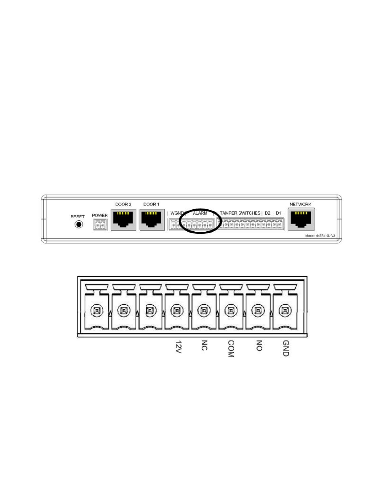
Using the Alarm Output
• Certain events create an alarm condition. These events are:
~ A door/panel with a Tamper Switch Attached was opened.
~ A door/panel with a Door Contact Switch was opened without a valid fingerprint identification.
~ A door/panel with a Door Contact Switch was opened and left open for longer than the Propped Door
Delay (set via the DAS software).
~ A Duress Finger was used to open a cabinet. This will be a silent alarm at the cabinet, but will still trigger the
Alarm Output.
• The Alarm Output provides a method to connect the db ServerRack Access Control unit to a third-party product, to
alert it that an alarm condition has occurred.
• The Alarm Output terminals are shown in Figures 19a and 19b.
Figure 19a
Figure 19b
• 12V can be used to provide a 12 Volt supply to an external device.
• NC is the Normally Closed relay contact
• COM is the Common relay contact
• NO is the Normally Open relay contact
• GND can be used in conjunction with 12V to provide a 12 Volt supply to an external device.
Model: db ServerRack V2 Zero-U Digitus Biometrics, Inc. 2011
Page 19 of 24
Page 20

Using the Wiegand Output
• The db ServerRack Zero-U v2 offers a 26-bit Wiegand output, allowing seamless integration into 3rd-party Access
Control System.
• The diagram shows how to connect a Control Unit to a 3rd-party system.
• The Wiegand Output terminals are shown in Figures 20a and 20b.
• D1 is Data 1 of the Wiegand Output.
• D0 is Data 0 of the Wiegand Output.
• GND is the Wiegand Ground
Figure 20a
Figure 20b
Model: db ServerRack V2 Zero-U Digitus Biometrics, Inc. 2011
Page 20 of 24
Page 21

Using the Door 2 Output
• In addition to the BioLock installed on Door 1, there is an option to install another device on Door 2.
• The device options for Door 2 are:
I A 2
II An Electro-Mechanical Lock that is operated simultaneously with the BioLock on Door 1.
nd
BioLock that works independently from Door 1.
Install the 2nd BioLock (Option I)
• Follow the steps on pages 5 thru 11 to install the 2
separately and can be ordered from your db ServerRack Access Control supplier)
• Connect the CAT5 cable to the port labeled "DOOR 2" on the back of the Control Unit as shown in Figure 21.
DO NOT CONNECT THE "DOOR INTERFACE BOX" CABLE TO THE PORT LABELED "NETWORK"
nd
BioLock to another cabinet door. (Note, this item is sold
Figure 21
Install the Electro-Mechanical Lock (Option II)
• The lock is supplied with a 10' cable with a RJ45 connector on one end (this connects as shown in Figure 22), and a
lock connector on the other end. The cable is shown in Figure 23. (Note, this item is sold separately and can be
ordered from your db ServerRack Access Control supplier)
• Mount the lock as shown in Figure 9, then attached the supplied cable, Figure 23
DO NOT CONNECT THE "DOOR INTERFACE BOX" CABLE TO THE PORT LABELED "NETWORK"
Figure 22
Model: db ServerRack V2 Zero-U Digitus Biometrics, Inc. 2011
Page 21 of 24
Page 22

Figure 23
Model: db ServerRack V2 Zero-U Digitus Biometrics, Inc. 2011
Page 22 of 24
Page 23
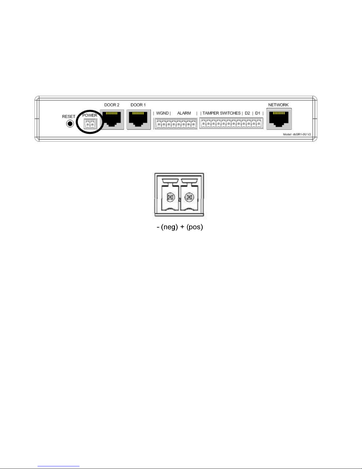
Connecting Power to the Control Unit
• Connect the supplied power supply as shown in Figures 24 and 25.
• Plug the power supply into a standard power outlet, a Power Distribution Module (PDU) or preferably an
Uninterruptable Power Supply (UPS).
Figure 24
Figure 25
• The Negative terminal of the Power Supply must be connected to the left terminal (as viewed from the rear of the
Control Unit)
• The Positive terminal of the Power Supply must be connected to the right terminal (as viewed from the rear of the
Control Unit)
IF THE POWER SUPPLY IS WIRED BACKWARDS, THE CONTROL UNIT WILL NOT POWER UP. THE UNIT HAS
PROTECTION TO PREVENT IT FROM BEING DAMAGED IF WIRED INCORRECTLY.
Model: db ServerRack V2 Zero-U Digitus Biometrics, Inc. 2011
Page 23 of 24
Page 24

Digitus Biometrics, Inc.
2 East Bryan Street, Ste 502
Savannah, GA 31401 USA
Phone: 912-231-8175
Fax: 912.629.9478
www.digitus-biometrics.com
support@digitus-biometrics.com
Specifications subject to change without notice.
Model: db ServerRack V2 Zero-U Digitus Biometrics, Inc. 2011
Page 24 of 24
 Loading...