

Page 1
db NEXUS V3.0.0
Installation Manual
Page 2

Table of Contents
FCC Notice for db Nexus III ................................................................................................................................................................................... 3
Mounting the Head Unit ........................................................................................................................................................................................ 4
Mounting the Control Unit .................................................................................................................................................................................... 5
Connecting the Head Unit to the Control Unit .............................................................................................................................................. 6
Connecting the Power Source to the Control Unit ....................................................................................................................................... 7
Connecting an Electric Strike to the Control Unit ......................................................................................................................................... 8
Fail Safe Locks and Magnetic Locks (12V) ....................................................................................................................................................... 8
Fail Secure Locks (12V) ............................................................................................................................................................................................ 9
Fail Safe Locks and Magnetic Locks (24V) ....................................................................................................................................................... 9
Fail Secure Locks (24V) ......................................................................................................................................................................................... 10
Request to Exit (RTE) Switch............................................................................................................................................................................... 11
Door Sensor ............................................................................................................................................................................................................. 12
Fire Panel Integration ........................................................................................................................................................................................... 14
Wiegand Output (26-bit protocol) .................................................................................................................................................................. 17
Powering Up the Unit ........................................................................................................................................................................................... 19
Models: db Nexus II, Nexus III Digitus Biometrics, Inc. 2011
Page 2 of 20
Page 3

FCC Notice for db Nexus III
This equipment has been tested and found to comply with the limits for a Class A digital device, pursuant to part 15 of
the FCC Rules. These limits are designed to provide reasonable protection against harmful interference in a residential
installation. This equipment generates, uses and can radiate radio frequency energy and, if not installed and used in
accordance with the instructions, may cause harmful interference to radio communications. However, there is no
guarantee that interference will not occur in a particular installation. If this equipment does cause harmful interference to
radio or television reception, which can be determined by turning the equipment off and on, the user is encouraged to
try to correct the interference by one or more of the following measures:
• Reorient or relocate the receiving antenna.
• Increase the separation between the equipment and receiver.
• Connect the equipment into an outlet on a circuit different from that to which the receiver is connected.
• Consult the dealer or an experienced radio/TV technician for help.
Caution: Any changes or modification cautions to this device not explicitly approved by manufacturer could void your
authority to operate this equipment.
This device complies with part 15 of the FCC Rules. Operation is subject to the following two conditions: (1) This device
may not cause harmful interference, and (2) this device must accept any interference received, including interference that
may cause undesired operation.
Models: db Nexus II, Nexus III Digitus Biometrics, Inc. 2011
Page 3 of 20
Page 4
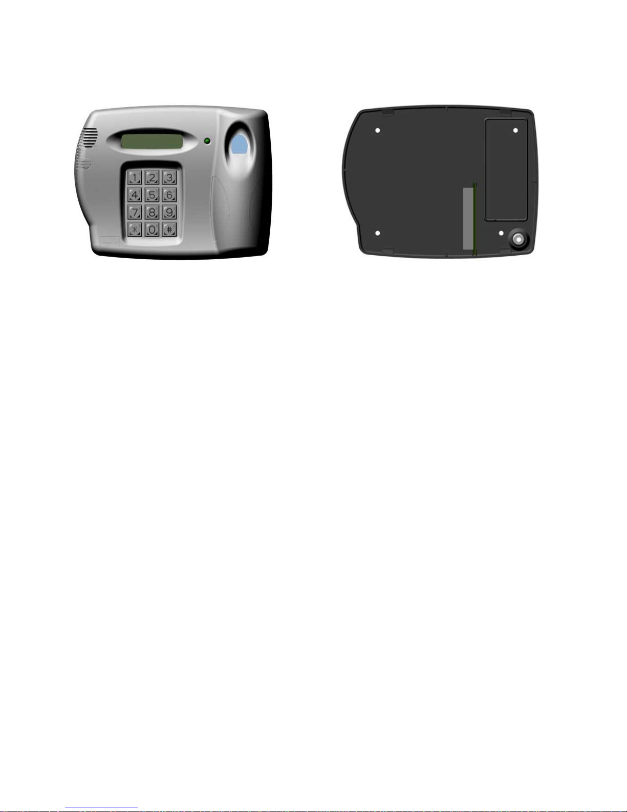
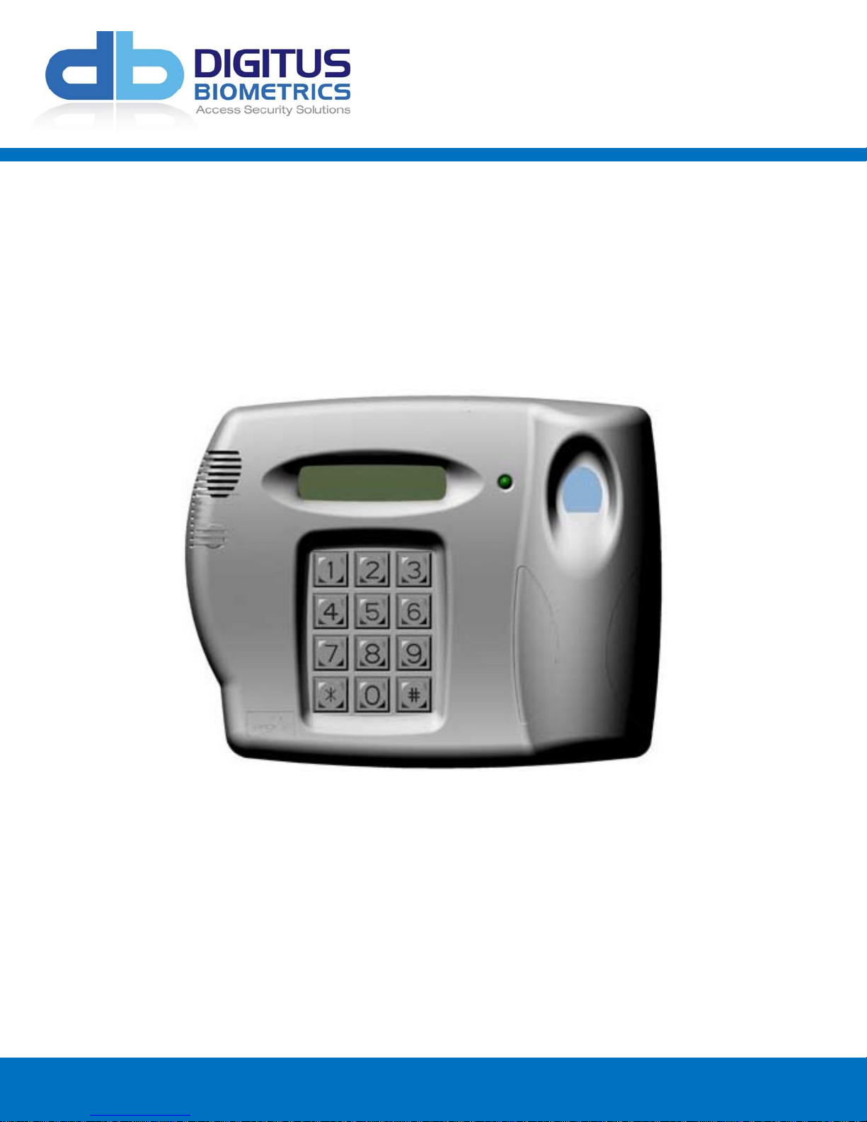
Mounting the Head Unit
Front Section
Back Section
Locate a surface adjacent to the opening side of the door, making sure that a person can stand directly in front of the
unit without obstruction. The unit should be positioned (where possible) on the wall so that the user’s forearm is
approximately 90 degrees to the wall during operation.
Prior to locating the back section of the head unit, double check that the cable passageway through the wall is
clear from obstruction (e.g. pipes, cables, etc.)
• Locate the back section of the head unit (or use the template provided in Appendix I) using a spirit level to
ensure that the plate is level.
• Inscribe the 4 screw holes and cable passageway (bottom right) with a pencil on the wall.
• Drill and plug (where necessary) the wall where the 4 mounting screws are to be fixed.
• Drill through the wall where you have marked the cable passageway, so that the cable can be passed directly
into the rear of the unit.
• Mount the back plate of the head unit to the wall using screws appropriate for the surface being fastened to.
Models: db Nexus II, Nexus III Digitus Biometrics, Inc. 2011
Page 4 of 20
Page 5

Mounting the Control Unit
The control unit can be placed above a false ceiling or high up out of general reach,
as no user interaction is necessary with this unit once installation is complete. Alternatively, all of the control
units can be located centrally in a communication closet.
The maximum distance between the head unit and the controller is 500 feet.
In order to make the process of mounting the control unit and connecting it to
the head unit as easy as possible, we recommend removing the 12v battery.
• Locate a suitable flat surface on the
inside of the protected door
• Ensure that the unit is level and inscribe the 4 screw holes with a pencil on the wall.
• Drill and anchor the wall (where necessary) where the 4 mounting screws are to be fixed.
• Mount the control unit to the wall using screws appropriate for the surface being fastened to.
.
Models: db Nexus II, Nexus III Digitus Biometrics, Inc. 2011
Page 5 of 20
Page 6
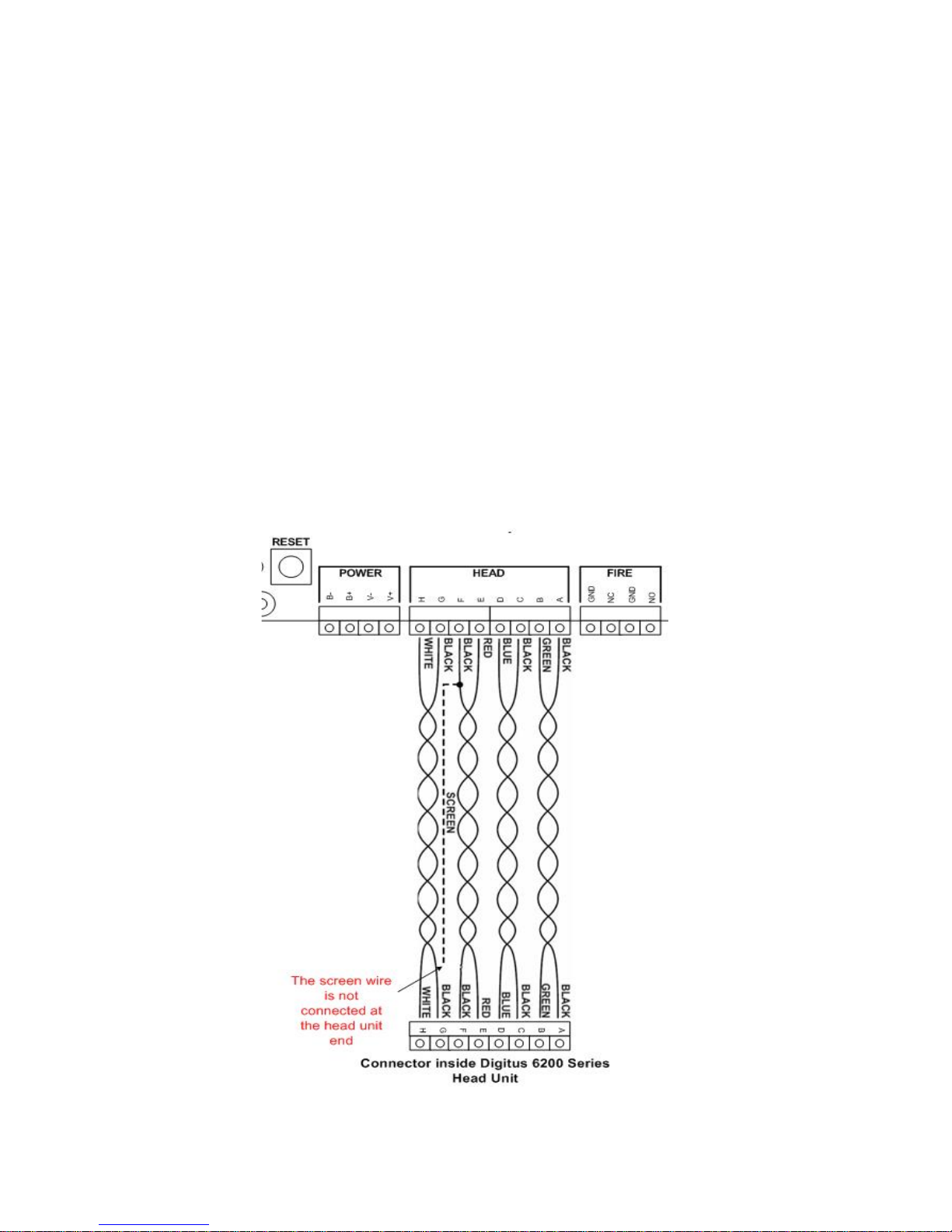
Connecting the Head Unit to the Control Unit
• Once the control unit and the back plate of the head unit are securely mounted, run a 4-pair (8 conductor) cable
between the head unit and control unit. A Belden 9504 or equivalent should be used.
• The cable should leave the control unit via one of the push-out holes located on the bottom of the unit, running
neatly along the wall and into the hole drilled through the rear of the head unit. Leave approximately 8”
(200mm) of cable spare at each end to allow for stripping the wires and connection to the terminal blocks. We
also recommend allowing an extra 12” to 18” of cable to be left as a service loop behind the surface you are
mounting to.
• The cable should be wired as shown below. The actual colors are not important but each pair of wires must be
connected as shown in the diagram.
• Wire the head unit as shown below.
To simplify the wiring the 2-part connectors can be removed from the boards.
• Strip approximately ¼” (6mm) of sheath from each cable and insert into terminal blocks, checking that all wires
are securely fastened.
• Repeat the procedure at the control unit.
Models: db Nexus II, Nexus III Digitus Biometrics, Inc. 2011
Page 6 of 20
Page 7

Connecting the Power Source to the Control Unit
Please ensure that you have a power outlet near the control unit
which will ONLY be used to supply power to the control unit.
ONLY the transformer supplied by Digitus should be used to power the control unit
(or an exact equivalent).
• Strip approximately ¼” (6mm) of plastic sheath from each cable to the power supply and connect to the
appropriate terminal blocks, checking that all wires are securely fastened.
• If you previously removed the battery (as recommended), please reinstall it and fasten securely.
• Reconnect the battery as shown below.
Models: db Nexus II, Nexus III Digitus Biometrics, Inc. 2011
Page 7 of 20
Page 8

Connecting an Electric Strike to the Control Unit
• Fit an appropriate lock to the door.
• The type of lock used determines how the control unit is wired.
Fail Safe Locks and Magnetic Locks (12V)
• A fail-safe or magnetic lock is permanently supplied with a 12V supply to keep the lock closed.
• Connect the Ground Lead of the lock to a terminal labeled 0V.
• Connect the Live Lead of the lock to the terminal labeled Door Solenoid.
• Connect a link between Link and NC and a link between COM and 12V
Models: db Nexus II, Nexus III Digitus Biometrics, Inc. 2011
Page 8 of 20
Page 9

Fail Secure Locks (12V)
• A fail secure lock needs supplying with a 12V supply to open the lock.
• Connect the Ground Lead of the lock to the terminal labeled 0V.
• Connect the Live Lead of the lock to the terminal labeled Door Solenoid.
• Connect a link between Link and NC and a link between COM and 12V
Fail Safe Locks and Magnetic Locks (24V)
• A fail-safe or magnetic lock is permanently supplied with a 24V supply to keep the lock closed. The Digitus
controller does not supply a 24V output. To use a 24V lock a separate power supply will be required. Wire a 24V
Fail Safe lock as shown in the diagram:
Models: db Nexus II, Nexus III Digitus Biometrics, Inc. 2011
Page 9 of 20
Page 10

Fail Secure Locks (24V)
• A fail secure lock needs supplying with a 24V supply to open the lock. The Digitus controller does not supply a
24V output. To use a 24V lock a separate power supply will be required. Wire a 24V Fail Safe lock as shown in
the diagram:
Models: db Nexus II, Nexus III Digitus Biometrics, Inc. 2011
Page 10 of 20
Page 11

Request to Exit (RTE) Switch
• The control unit has a built-in delay for the RTE switch.
• Connect a push-switch as shown in the diagram below. The exit delay is set through the PC software on a
networked unit or through the menus on the head unit for a standalone.
Models: db Nexus II, Nexus III Digitus Biometrics, Inc. 2011
Page 11 of 20
Page 12

Door Sensor
• The door sensor contacts are used for the forced door and propped door features.
• Connect the door sensor as shown below.
• The door sensor circuit provides a feature to work with a special type of door sensor, that is tamper proof. This
prevents an internal security breach, where someone with authorized access to an area could potentially shortout the contacts on the door sensor. If used with the anti-tamper door sensors, the jumper of SW SEL (JMP1)
must be set as follows.
Models: db Nexus II, Nexus III Digitus Biometrics, Inc. 2011
Page 12 of 20
Page 13

If the door sensor is not being used, the link must remain in place as
shown below.
Models: db Nexus II, Nexus III Digitus Biometrics, Inc. 2011
Page 13 of 20
Page 14

Fire Panel Integration
• Units can be connected to a fire panel so that in the event of a fire, required doors can automatically unlock.
• Once a door has been unlocked via the fire override inputs, the unit must be reset manually by pressing the
reset button on the control unit. Doors will remain unlocked until the unit has been reset.
• The diagram shows how to connect a control unit to a fire panel. The unit can be connect to either a normally
open or normally closed set on contacts as shown below.
• Only remove the link between 0V and NC is the system is wired as follows.
• Locating the reset switch
R
eset Switch
Models: db Nexus II, Nexus III Digitus Biometrics, Inc. 2011
Page 14 of 20
Page 15

If the fire panel integration is not being used, the link must remain in
place as shown below.
Models: db Nexus II, Nexus III Digitus Biometrics, Inc. 2011
Page 15 of 20
Page 16

Alarm Output
• Certain conditions that occur on the unit will cause the Alarm Relay to operate. The Alarm Relay can be used to
interface the control unit with a 3rd party system. When one of the following conditions happen, the 3rd party
system will be alerted.
• The following will send an alarm alert:
~ Tamper detected on the head unit
~ A forced door
~ A door being propped open
~ The duress feature being activate
~ A tamper detected on the door sensor circuit (when used in conjunction with an anti-tamper door sensor)
• The alarm relay is connected as per the diagram below.
• Alternatively the alarm relay can be used to power a 3rd party buzzer or siren.
Models: db Nexus II, Nexus III Digitus Biometrics, Inc. 2011
Page 16 of 20
Page 17

Wiegand Output (26-bit protocol)
• The db Nexus controller offers a 26-bit Wiegand output, allowing seamless integration into 3rd-party Access
Control System.
• The diagram shows how to connect a control unit to a 3rd-party system.
Models: db Nexus II, Nexus III Digitus Biometrics, Inc. 2011
Page 17 of 20
Page 18

Network Connection
• If the unit is networked, connect the RJ-45 plug as shown below.
Models: db Nexus II, Nexus III Digitus Biometrics, Inc. 2011
Page 18 of 20
Page 19

Powering Up the Unit
• Plug the transformer in to the power outlet and ensure the supply is switched on.
• The unit should now power up. If not, unplug the unit and check all wiring.
• The buzzer on the control unit should sound for 1 second.
Check the LCD display.
If the display reads “LCD CONTRAST (0-9):[0] #=DONE the unit is OK.
• If the unit does not get to this stage, or displays a different message, check that the cable between the head
unit and control unit has been wired correctly.
Models: db Nexus II, Nexus III Digitus Biometrics, Inc. 2011
Page 19 of 20
Page 20

Digitus Biometrics, Inc.
2 East Bryan Street, Ste 502
Savannah, GA 31401 USA
Phone: 912-231-8175
Fax: 912.629.9478
www.digitus-biometrics.com
support@digitus-biometrics.com
Specifications subject to change without notice.
Models: db Nexus II, Nexus III Digitus Biometrics, Inc. 2011
Page 20 of 20
 Loading...