

Page 1
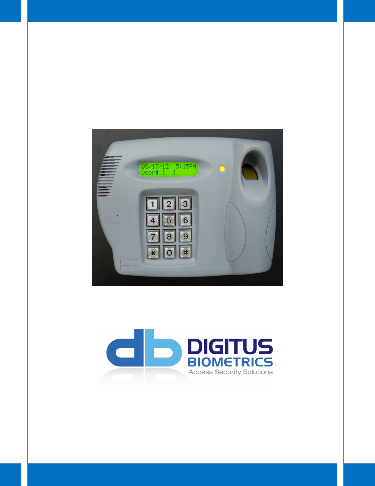
db Enline
Installation and User Manual
Page 2

Model: db Enline
TABLE OF CONTENTS
db ENLINE OVERVIEW ....................................................................................... 2
INSTALLATION THE db ENLINE UNIT...................................................................... 3
SUGGESTED WIRING CONFIGURATION .................................................................. 6
USING THE db ENLINE UNIT ................................................................................ 7
P a g e | 1
Page 3

Model: db Enline
db ENLINE OVERVIEW
The db Enline unit is a device used with the db Bus architecture. The db Enline unit is used in the
db ServerRack – End-of-row solution, as a user input device. The unit allows a user to specify
which door they are attempting to access, and then allows them to authenticate their credentials
(PIN/Fingerprint/RFID). If the user enters a valid door number and has access to the door at the
time of requesting access, the door will unlock.
P a g e | 2
Page 4

INSTALLATION THE db ENLINE UNIT
It’s important to record the serial number and location of each db Enline Unit installed. The db
Enline’s serial number is used to identify it within the Digitus DAS-SQL software.
There is no limit to the number of db Enline units that can be installed on a db Bus, as long as:
(db Enline Units + Remote Nodes <= 32)
Typically one db Enline Unit would be installed at the end of each row of cabinets.
The Enline unit comes in two parts, the front section and the back section.
Model: db Enline
Front Section
Back Section
Locate a suitable mounting surface for the db Enline unit. This would typically be on the end of a
row of cabinets. A person using the db Enline unit should be able to stand directly in front of the
unit without obstruction.
• Use the enclosed mounting template to mark the location for the mounting and cable
pass-through holes. Ensure the template is level prior to marking by using a torpedo level.
It is highly recommended that the side panel be removed from the cabinet and the drilling be done
outside of the data center. This will prevent the possibility of any metal shavings being drawn into
electrical equipment.
• Drill the cabinet where the 4 mounting screws are to be fixed.
P a g e | 3
Page 5

Model: db Enline
• Drill the cabinet where you have marked the cable passageway, so that the cables can be
passed directly into the rear of the db Enline unit.
• Mount the back plate of the db Enline unit to the cabinet using the supplied mounting
hardware.
• The Enline unit attaches directly to the Digitus db Bus. Pass the db Bus cables from the
inside of the cabinet, through the cable pass-through hole.
P a g e | 4
Page 6

• Connect the db Bus cables to the RJ-45 sockets as shown in Figure 1.
Model: db Enline
Figure 1
• Route the cables as shown in Figure 2.
Figure 2
• Insert the 4 mounting lugs on the front section of the db Enline unit into the 4 mounting
holes on back section of the db Enline unit.
• Secure the db Enline unit with the 4 supplied screws.
P a g e | 5
Page 7

Model: db Enline
SUGGESTED WIRING CONFIGURATION
In order to prevent any individual cable-length from being too long, please follow the suggested
wiring configuration:
The diagram below shows a top down view of a row of server cabinets. The db Bus Controller is located in
the far left cabinet, with a Remote Node, and all other cabinets contain just a Remote Node. The db Enline
Unit is installed on the outside of the far right cabinet.
Figure 3
Refer to the db ServerRack Bus Controller manual for db Bus Controller and Remote Node
installation.
P a g e | 6
Page 8

Model: db Enline
Row# [ ]
USING THE db ENLINE UNIT
The configuration of the db Enline unit is done via the DAS-SQL Management Software.
Door Identification
The user is first prompted to identify which door they are attempting to open.
There are three possible criteria that can be used to identify the door a user is attempting to
access:
• Row Number
• Cabinet Number
• Door Number
Row Number and Cabinet Number are optional, whereas a Door Number is always required. Thus
the options available are:
• Row Number + Cabinet Number + Door Number
• Row Number + Door Number
• Cabinet Number + Door Number
• Door Number only
The number is digits required for each item is set through the DAS-SQL Management Software.
The [ ] (square brackets) indicate the number of digits required. Leading zeros are required to
ensure the correct number of digits, e.g. If the requested Row# is “3” and the required number of
digits is two, the row number should be entered as “03”.
22/05 / 12 1 1: 06
# Key Requirement
The db Enline can be configured to either require a # key to be pressed after each piece of data
entered, or to automatically proceed to the next menu item, once the required number of digits
has been entered. This is also set through the DAS-SQL Management Software.
22/05 / 12 1 1: 06
Row# [ 06 ]
Waiting for #key #key not require, automatically
P a g e | 7
22/05 / 12 1 1: 06
Cabi n et# [ ]
proceeds to next menu item
Page 9

Model: db Enline
TIME CODE
Row no t fou n d
Incorrect Selection
If an incorrect parameter is entered, a message will indicate this on the db Enline unit.
User Authentication
Once the door identification parameters have been correctly entered, the user must then
authenticate. This will determine whether the user has access to the specified door. The db Enline
II unit allows up to two credentials to be used for authentication, PIN and fingerprint. The db
Enline III unit allows up to three credentials to be used for authentication, PIN, RFID card and
fingerprint. The required credentials are configured through the DAS-SQL Management Software.
The user must provide the credentials as requested by the db Enline unit:
22/05 / 12 1 1: 06
ENTE R I D: [ ]
22/05 / 12 1 1: 06
PLACE FINGE R
User is required to enter User is required to place
a 4-digit PIN number. finger on the scanner.
Access Granted/Denied
Based on verification of the credentials, access is either granted or denied.
Acce s s Grant e d
Acce s s Denie d
Access Granted Access Denied
Following a successful access, the specified door will unlock.
Time Restriction
It’s also possible to restrict what times a user has access to each door. The db Enline unit will
check that the user is attempting access within their permitted times. If access is attempted
outside a user’s permitted times, the following message will be displayed.
P a g e | 8
OUTS I DE VAL I D
Page 10

Model: db Enline
Digitus Biometrics, Inc.
2 East Bryan Street, Suite 502
Savannah, GA 31401 USA
Phone: 912-231-8175
Fax: 912.629.9478
www.digitus-biometrics.com
support@digitus-biometrics.com
P a g e | 9
 Loading...