

Page 1

DIGITUS
®
Plug&View IP
cameras
User Guide
Page 2

Plug&View IP camera ׀ Manual ׀ EN-201310 2
1 Introduction:
The Plug&View IP camera series by DIGITUS offers P2P cloud services in order to avoid the
complicated network configuration for the camera installation. Everything you need is "Plug&View"
and a few installation steps.
2 Supplied with:
- 1 X IP camera
- 1 X AC adapter
- 1 X ethernet cable
- 1 X installation CD
- 1 X Mounting Accessories
- * DN-16038/DN-16039/DN-16040/DN-16043/DN-16044 also include a built in 2GB memory for
storage.
3 Installation procedure:
3.1 Connect
Please follow the instructions of the Quick Start Guide to connect your Plug&View camera and to
start using it from your user account. Then log in to your user account in http://plug-view.com. After a
successful login you will see an overview of the images of your registered cameras.
4 Description of the toolbar
The toolbar can be found to the right side above the image of each IP camera. Here
you can quickly see the operational readiness and make various settings.
4.1 LED display symbols
Green light
When the green light is ON, your IP camera is online und sending. The video image is
successfully displayed on the screen.
Yellow light
When the yellow light is ON, the IP camera is online, but not yet sending. No video image is
displayed on the screen.
Red light
When the red light is ON, the IP camera is offline and nothing is displayed on the screen.
4.2 Full Screen
The 'Full Screen' button opens a new screen for better viewing of the video image, which is then
displayed across the entire screen.
Page 3
Plug&View IP camera ׀ Manual ׀ EN-201310 3
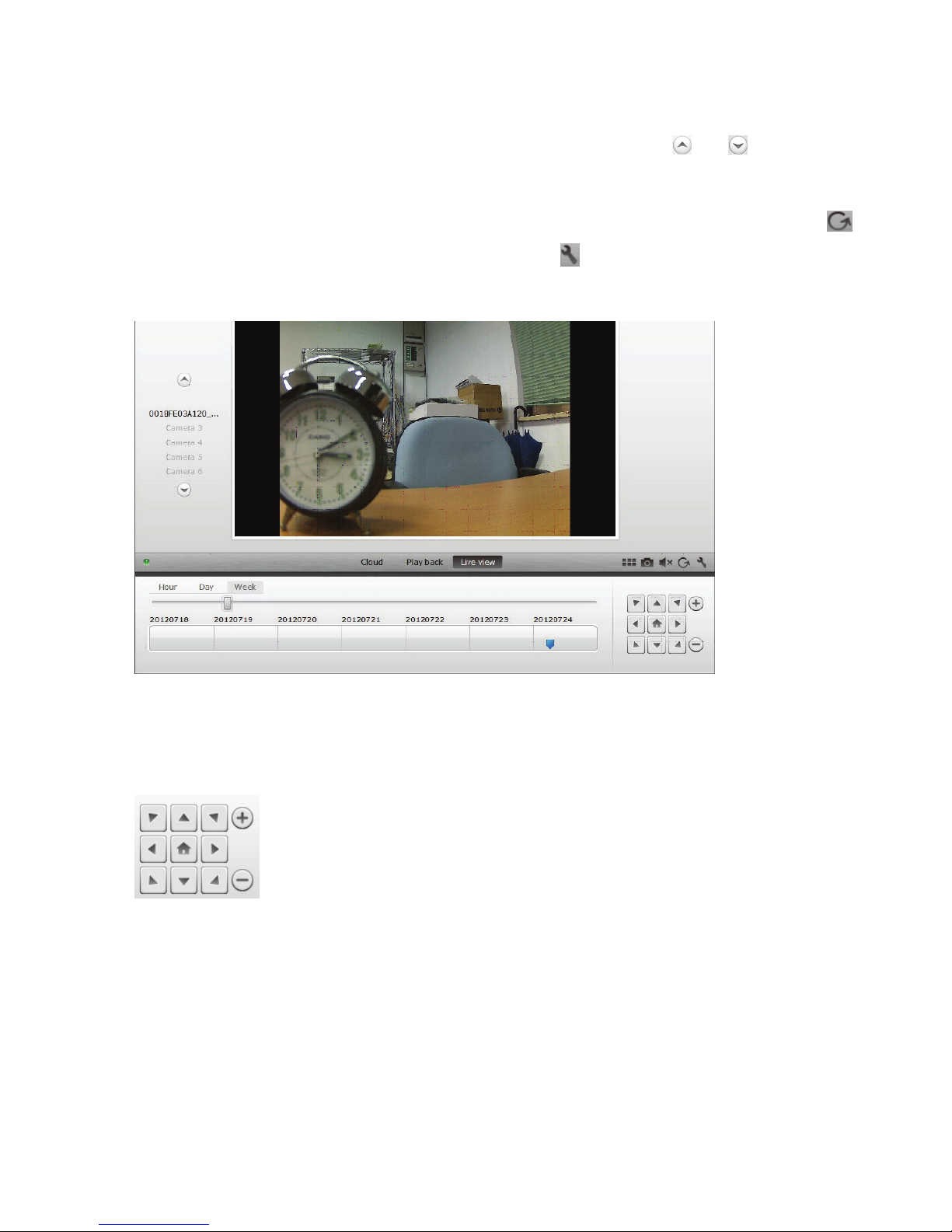
4.3 Live image and PTZ
The button "Live View" will display the live-stream or images from the selected IP camera in real-
time. If you have multiple plug&view cameras installed, you can switch between the different cameras
using the display on the left-hand side of the screen. Use the arrow buttons and to select other
IP cameras from the list.
In the event of connection problems, e.g. because of a slow Internet connection, you can click on
to reload the live-stream or real-time images. By clicking on , on the right side at the bottom of the
screen, one can access the configuration controls for the selected camera.
If the selected IP camera supports PTZ functions, the PTZ control panel, with which you can control
the camera, can be selected. Otherwise the field will be grayed out to indicate that it has no function.
Each motion adjustment requires a click.
4.4 Playback
The "Play back" function is only supported when an SD-card for media recording has been inserted
into the IP camera. By using the blue tags on the time axis, all recorded events can be retrieved. All
recorded events have been stored and tagged with a blue mark on the time axis. You can select to
view them for different time periods, by clicking on the left side of the time axis, on hour (hour), day
(day) or week (week).
Page 4

Plug&View IP camera ׀ Manual ׀ EN-201310 4
When hovering over a blue tag with the mouse, the color changes to orange and the details of the
recorded clips are displayed. Select a specific clip to check this.
During playback of the selected media clip, you can stop or pause it, or switch to the next clip, using
the media control buttons. You can also drag the marker of the video search control to the
desired position in the playback.
Settings
The Settings button opens up a special web user interface for the configuration of the IP camera.
Please log in with "admin" as the username and
password.
Muting
With the button, you can switch the sound of the camera on or off.
Refreshing
With the Refresh button you can refresh or reload the video image on you IP camera.
Deleting
With the Delete button , you can delete specific IP camera medium from the overview page.
Screenshot
With the Photo button you can take a still shot of the current video image and save it directly to
your PC.
Click on the top right of the screen to exit the full-screen mode or click on the bottom right side
to return to the matrix display page.
Page 5

Plug&View IP camera ׀ Manual ׀ EN-201310 5
In the camera matrix, click on "Settings" in order to see the list of cameras.
In this list you can see the details of your camera(s) and by clicking on change the name of the
camera, with you can remove a specific camera from your account and with the hook button
underneath "Device Matrix" select if she should be displayed with a Live Image in the overview.
By clicking on the "Plus" symbol on the left, above the list, an additional
camera can be registered to your account.
Google Drive Backup
To the right your Google Drive Account for the cloud-backup is set up. You must have a
microSD memory card installed in your camera in order to be able ot use Google backup.
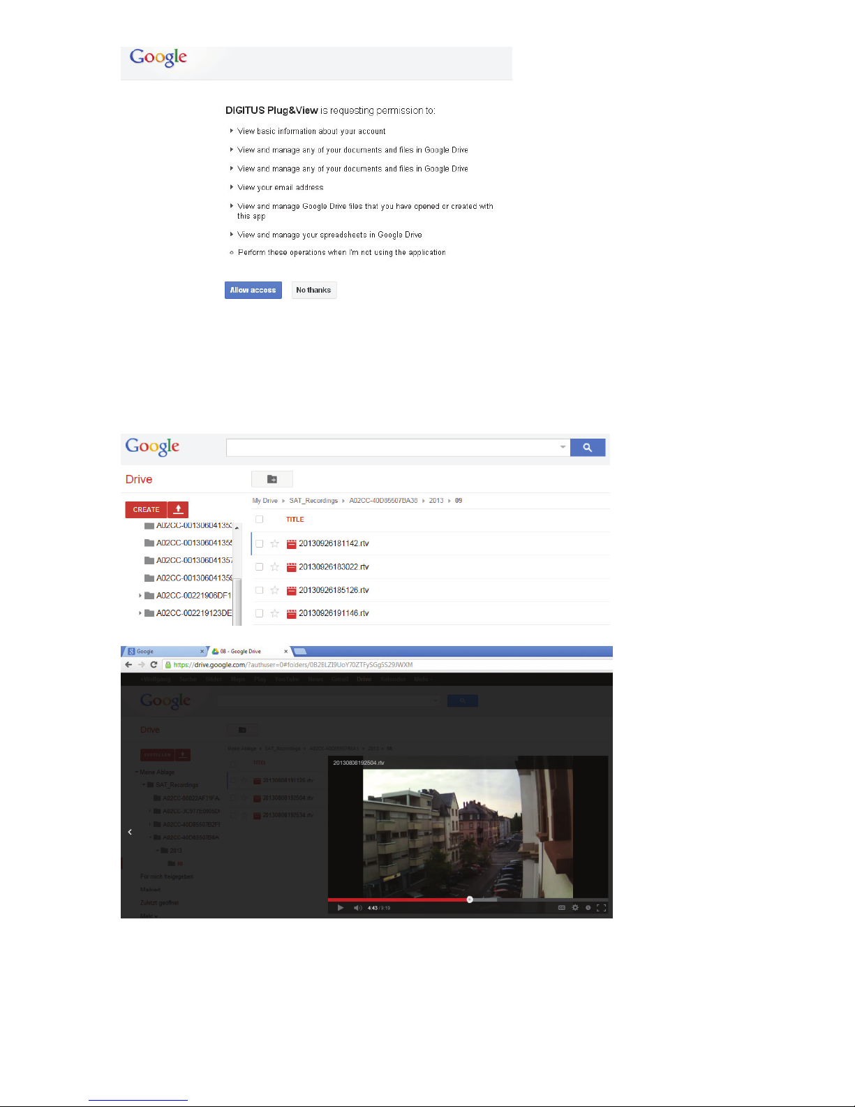
Please click on the button "Google authentication" and then accept the request in the following
window to use "Google Drive" as cloud storage, by clicking on "OK".
You will be redirected to the Google drive registration page. Please enter your Google Mail address
and password, if you already have an account.
After entering your Google account information, please accept the access rights to allow for the video-
backup from the camera to the Google drive. The windowwill then close automatically.
Page 6
Plug&View IP camera ׀ Manual ׀ EN-201310 6
Through the storage function of Google-Cloud, a copy of your video files from the microSD-card is
loaded onto Google drive. This means, that the videos, triggered by movement or timer, can be
played from the cloud storage, online, using your browser. Please log in to your Google drive and
select the recorded video (RTV) files in the directory "SAT_Recordings" to watch the videos online.
Page 7
Plug&View IP camera ׀ Manual ׀ EN-201310 7
5 Camera User Interface
The camera user interface has 6 menu items (Home, Replay, Log, Parameters, System and WiFi).
In order to be able to use the multimedia and control functions, the OCX component must be installed
in Internet Explorer and the VLC Mediaplayer in Firefox and Chrome. A download link will be
displayed in the user interface if necessary.
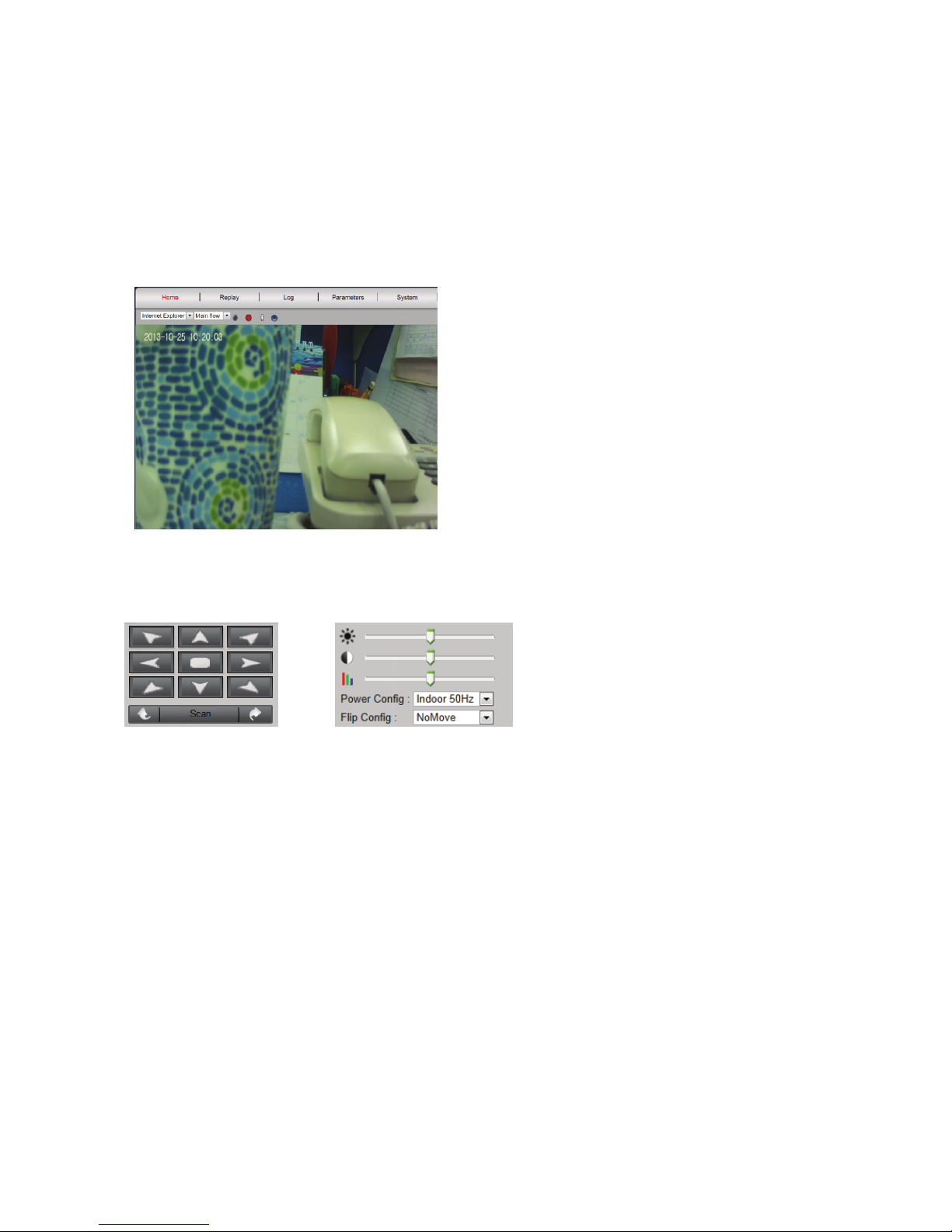
5.1 Home
This page shows the live image from the camera.
Under "Home" you can also Pan and Tilt (Plug&View Optiarc or similar PTZ cameras), as well as
control the video settings such as brightness, contrast and saturation.
5.2 Replay
5.3 Log
The log records all events such as motion detection or alarm. Select a date and then press the
Search button (magnifying glass) to list all events on this date. To view the recorded video, click on
"View".
Page 8

Plug&View IP camera ׀ Manual ׀ EN-201310 8
5.4 Parameters
This is where you configure Network, Video Parameter, DDNS & UPnP, Video Cover, motion
detection, Alarm Setting, CMOS Sensor and Monitor.
5.4.1 Network
Here you assign a fixed IP address to the camera, according to the configuration of your LAN, or
select DHCP if you are using a DHCP-server, such as your router, for the assigning of IP-addresses.
The ports for HTTP, RTSP and RCFG can be modified here, if port forwarding settings are required
on your router.
Page 9

Plug&View IP camera ׀ Manual ׀ EN-201310 9
5.4.2 Video Parameter
Under Video Parameter you can configure the resolution, bit rate, Type, frame rate and image quality
of the video stream.
You can choose between 'high' and 'normal video quality'. 'High Quality Video' is used mainly for
high-resolution video streams via a PC with higher clock frequencies and faster Internet connection.
'Normal video quality' is usually for use with mobile phones. The main- and sub stream modes
support Constant Bit Rate (CBR) and Variable Bit Rate (VBR). You can select between 5 levels in the
Image Quality settings: from very high to very low.
5.4.3 DDNS & UpnP
If you want to have additional access to the user interface via a DynDNS provider, activate Dynamic
DNS by selecting "on" and enter your domain and access data. If the camera handles the assignment
of the ports and the forwarding via UPnP, please note, to also adjust the necessary settings on your
router (changes to the security settings to allow UPnP).
5.4.4 Video Cover
"Video Screen" marks any specific area within the video image which is blacked out during a
recording. Activate Video Screen by clicking on "on". Then click inside the video image and drag with
the mouse button from the top left to the bottom right corner of the desired area. A high-lighted color
box will appear, which represents the covered area. Click on "Region 2" to select another area and
repeat the process. Once you have selected up to 4 areas, finish the process by clicking on "OK".
Page 10

Plug&View IP camera ׀ Manual ׀ EN-201310 10
5.4.5 Motion Detection
Enable the motion detection with a click on "On".
The colored area within the video image is the
motion detection area, i.e. the area in which a
movement triggers a picture or a video recording.
In the original delivery condition, almost the entire
screen is covered with red boxes. In order to
exclude certain areas from the motion detection,
clickin the bottom right cornerof the colored
marker and move the mouse towards the top
left, while holding the mouse key down.
By doing this, you delete the marker for that area. Respectively, you do the same in the opposite
direction, from top left to bottom right, to select a new area for motion detection. The sensitivity
ranges from 0 to 5, whereby the smallest value represents the highest sensitivity. The typical setting
is 3. The value behind "next motion detection after..." specifies after how many frames the motion
detection will be triggered again. By clicking on "OK" you complete the setting and will then receive a
message in a pop-up window, to set the 'Action' next, which should start as soon as the camera
registers a movement within the range. Confirm with "OK" and you will be automatically moved to the
"Alarm Setting".
Page 11

Plug&View IP camera ׀ Manual ׀ EN-201310 11
5.4.6 Alarm
There are three types of alarm setting: Motion detection, Alarm in (external alarm) and Time. To
activate the motion detection, click on the tab with the corresponding name. Please make the
settings under the right-hand menu "Motion Detection" first, as long as the coverage and the
sensitivity have not yet been set, as described in 6.1.5. Select the time frames for the motion
detection with the left mouse button in the time grid. Click on "Enable" and on "Record" to save the
video recording, which was triggered through motion detection, on the microSD card. You can also
setup e-mail notification of motion detection, as described below. By activating "Capture", a snapshot
will be triggered in the event of motion detection. This image will then be automatically sent to you as
an attachment with the e-mail notification.
Storing your videos/pictures on an FTP-server is also possible. Please enable FTP and press "Set
FTP" to enter your credentials. This function will then transfer all videos and pictures from the
microSD card to your FTP-server.
Enabling "DO Out" triggers a switch contact in the event of motion detection, which can be forwarded
to an alarm system via an external port of the camera (e.g. Plug&View Optiarc).
In the tab "Alarm In" the recording can be triggered externally through a passive switch contact, e.g.
a window or door sensor. Your camera must be equipped with an external connector (e.g. Plug&View
Optiarc) to be able to connect a suitable cable, through which the "Record", or "Capture" will be
triggered.
Page 12

Plug&View IP camera ׀ Manual ׀ EN-201310 12
With "Time" you can set the desired time for continuous recording to the microSD-Karte. You can, for
example, set the time for the normal working hours from Monday to Friday, from 09.00 to 18.00, by
marking the desired time period in the time grid with the mouse. The colored area means that in this
period the recording will be continuously running. A second click in the colored area deletes the time
window. Activate any time slot for the scheduled recording and specify whether videos and/or images
should be recorded and the time interval (e.g. every 5 seconds) at which the images should be taken.
Videos will be recorded on the SD card until the storage capacity is exhausted. Then, starting with the
oldest recording, the recordings will be overwritten.
5.4.7 CMOS Sensor
Here you will find various setting options for image optimization:
Page 13

Plug&View IP camera ׀ Manual ׀ EN-201310 13
The settings for "Flip Config" turn the video image by 180°, e.g. when the camera is installed on the
ceiling: "UpDown" – vertical rotation, "LeftRight" – horizontal rotation, "All" – verticale and
horizontal
rotation, "NoMove" – no rotation.
In "Power Config" determine the frequency of the site for the indoor or outdoor use of the camera. For
indoor installations and operation in Europe, select "Indoor 50Hz". For use outside Europe, e.g. in the
USA and Japan, select "Indoor 60Hz". For outdoor use (e.g. Plug&View OptiMax) select "Outdoor".
With the settings under "Brightness" you can optimize brightness, contrast and saturation of the
camera image. The default value is 128.
Under "CMOS" you can set the exposure value at which the camera switches back and forth between
day and night mode with the number behind "Wide Dynamic Range". If "IR Switch" is set to "On", the
integrated infrared LED it will be activated automatically in low light conditions. The "Off" setting
disables the LEDs and you can then specify in "Color Switch", whether the camera image should be
in black-and-white or color in low light conditions or, respectively, should automatically switch from
color to black-and-white.
"Electronic Level" to "High" or "Low" determines how sensitive the LEDs respond to changing lighting
conditions.
5.4.8 Monitor (text overlays)
You can make the time and camera name, as well as two additional textual information (Free Text)
display on the monitor (in the camera live image). The color and position of the characters are freely
adjustable.
Page 14

Plug&View IP camera ׀ Manual ׀ EN-201310 14
5.5 System
The system settings consist of Local Setting, Time Settings, System Tools, User Management and
Device Information.
5.5.1 Local Setting
Here you specify whether the login to your account should be done automatically. Here you can set
the video quality and for direct recording of images and videos via the local storage path to your
computer, while video playback is activated.
5.5.2 Time Settings
Manual setting, Sync with computer time, Sync with NTP and Time zone are optional. Select the
method you want to use. Select the method you want to use.
Manual setting: Enter time and date manually.
Sync with computer time: The time of the IP camera is automatically synchronized with your PC.
Sync with NTP: Enter the URL or IP address of the NTP server.
Time zone: Select the Time Zone according to your location.
Page 15
Plug&View IP camera ׀ Manual ׀ EN-201310 15
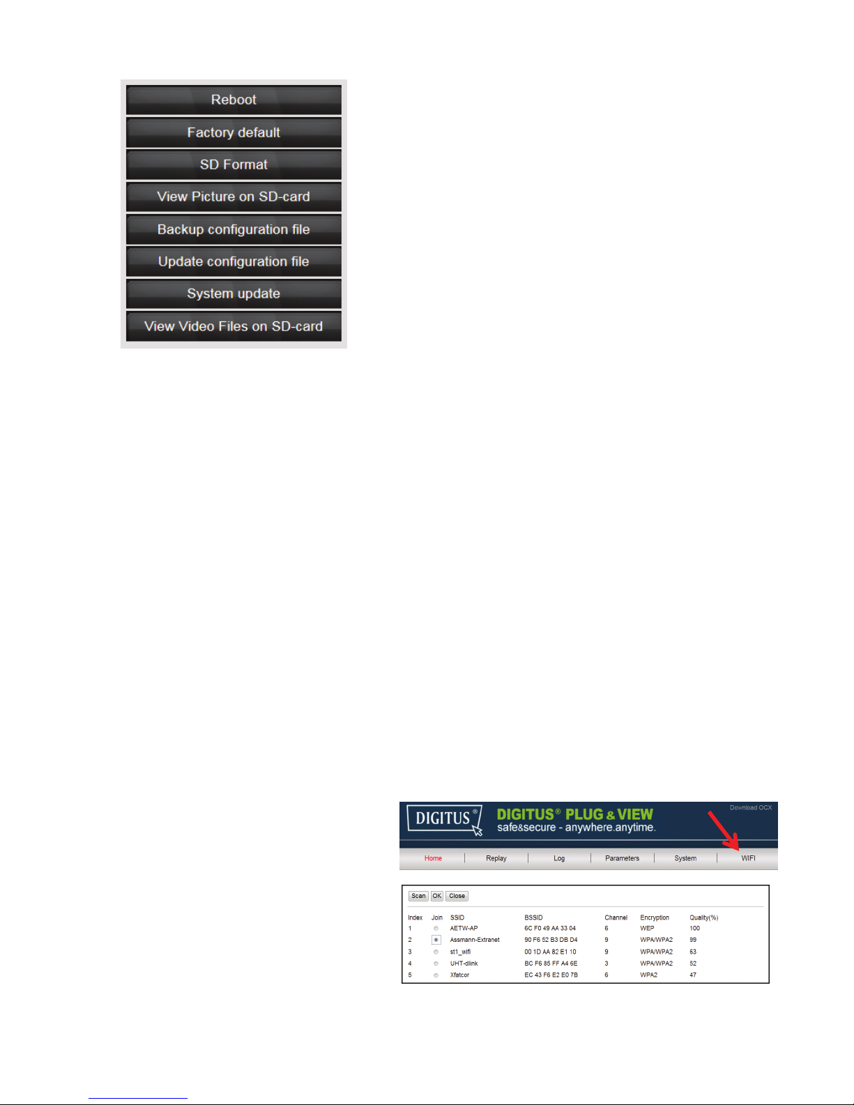
5.5.3 System Tools
Reboot – triggers a restart of the camera. After approx.
20 seconds you can log in again
Factory default – resets the camera to factory settings.
All of the changes you have made will be lost.
SC Format – formats (FAT32) an inserted SD-card for
video and images
View Picture on SD-card – displays the recorded
images
Backup configuration file – saves the current
configuration of the camera on your PC
Update configuration file – restores the camera
configuration you had preciously stored on your PC
System update– allows you to manually update the
firmware
View video files on SD-card – shows the recorded
videos
5.5.4 User Management
In the delivery state, you logged into the camera as Administrator. As admin you can create and
delete users, who have access to the camera user interface. Normal users do not have permission to
add or delete users.
5.5.5 Device Information
Here you can see all the important technical data concerning your camera at a glance: Brand and
Type, serial number, software (firmware) version, the MAC address of the Ethernet adapters, the
current Ethernet network settings, as well as the date and time of the last time the camera was
switched on. Under SD card information you can see the maximum available capacity of the microSD-
card (if installed).
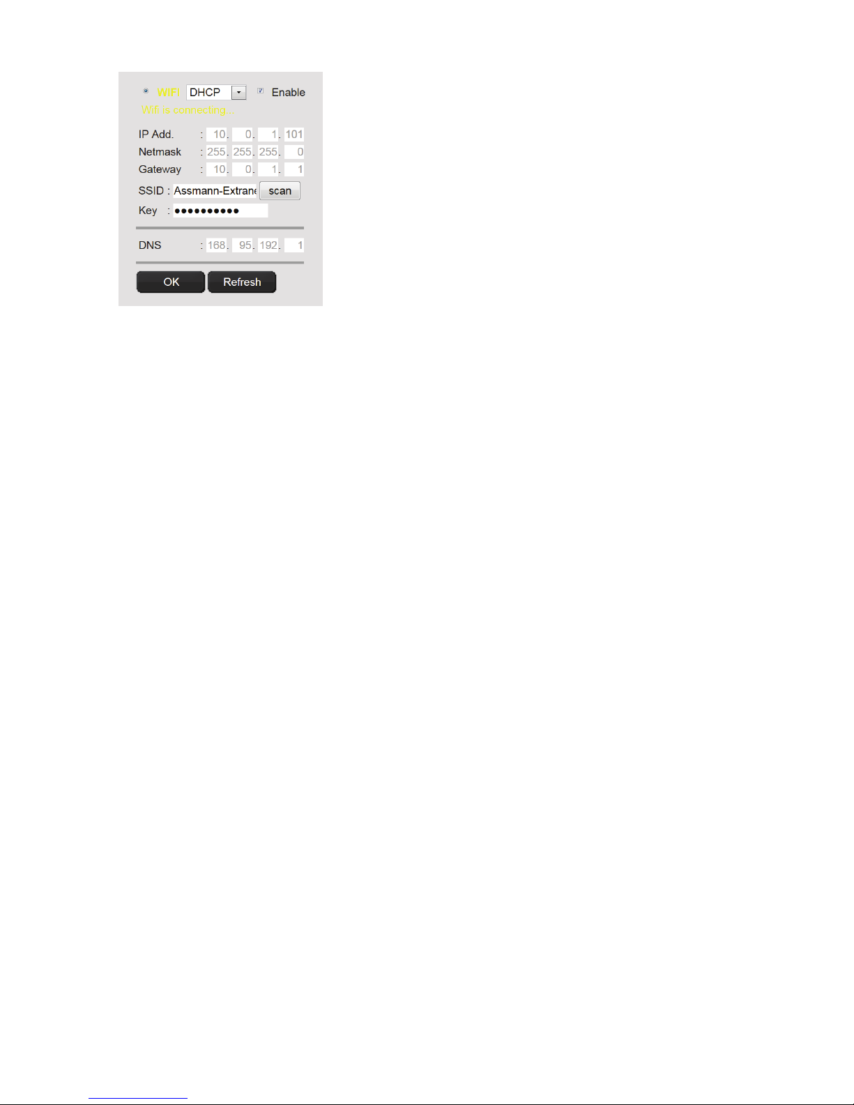
5.6 WIFI
In the user interface of the camera
click on WIFI, to configure the wireless
settings.
A search window will appear, in which
the available wireless networks in your
environment will be displayed. Please
select the identifier (SSID) of your
network and confirm with "OK".
Page 16
Plug&View IP camera ׀ Manual ׀ EN-201310 16
In the next window enter the WLAN-key and confirm with "OK".
Next, the connection to your wireless LAN is established. The
indication "Wifi connection will be established" is blinking in
YELLOW. If the connection was successfully established, this will
be displayed in a separate window. The display then changes to
"Wifi connection".
You can now remove the network cable from the camera and close
the browser window.
Trademarks
DIGITUS is a registered trademark ASSMANN Electronic GmbH.
Apple, Apple APP Store are registered trademarks of Apple Inc.
Android, Google, Google play are registered trademarks of Google Inc.
AVM Fritz!Box is a registered trademark of AVM Computersysteme Vertriebs GMBH.
Telekom Speedport is a registered trademark of Deutsche Telekom AG.
Note:
All other trademarks not listed here, are the property of their respective owners.
Trademarks or trade names mentioned in this manual are used to describe the operating steps and do not
imply that they are freely available. In any case they are the property of the respective holder of the rights.
The ASSMANN Electronic GmbH hereby declares that the IP cameras, type Plug&View, are in accordance
with the requirements and provisions of the Directive 1999/5/EC.
The full Declaration of Conformity can be found under http://www.digitus.info.
 Loading...