

Page 1
1
DIGITUS Plug&View
OptiVision / OptiArc / OptiMax /
Optimax Pro
User Manual
DN-16027 / DN-16036 / DN-16037 / DN-16040
DN-16036
DN-16037/DN-16040
DN-16027
Page 2

2
1 Introduction:
DIGITUS Plug&View series of IP cameras offers P2P Cloud service to avoid those complicated
network setting for camera installation. All you need is just “Plug&View” with 3 simple steps.
2 Package Content:
- IP camera x 1
- Power supply x 1
- Ethernet cable x 1
- Support CD x 1
- Mounting accessory x 1
- * DN-16040 has additional 2GB TF card included.
3 Installation Procedures:
3.1 Getting connected
1. Power on the camera and connect the Ethernet cable from the camera to the router.
Please make sure that the router is setup to be able to access Internet.
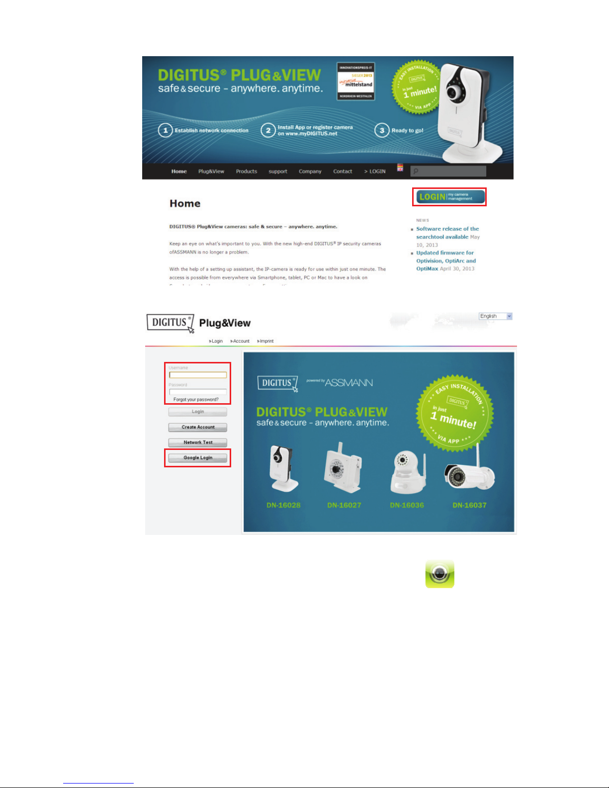
2. Open a browser (Internet Explorer, Google Chrome, Mozilla Firefox...) and key in
http://mydigitus.net/
to access DIGITUS Plug&View Website. Press “LOGIN” to enter the
login portal. Please create an account for first use. Alternatively, you can also use your
existing Google account to login by pressing “Google Login”. Then enter your account
and password.
Page 3
3
Alternatively you can also download “DIGITUS Plug&View” APP from APP store
or Google Play and execute this APP from your mobile devices and login the account
and password instead of using browser.
Page 4

4
3. With browser, please key in the MAC address and Activation code as shown on the last
page of the QIG to add camera under your account. After press “Apply”, it will show
“Success”.
Alternatively the easiest way to add camera without key-in long numbers is using the
smart phone to scan the QR code on the last page of the QIG using “DIGITUS
Plug&View” APP from your mobile devices.
After adding the camera, you can have live-view anytime anywhere.
3.2 Getting connected wirelessly
Wireless (WiFi) connection between IP cameras and Wireless router / Access point is also
available with the following procedures.
4. After completing Step 1 ~ 3 for wired connection with Ethernet cable, login into
http://login.mydigitus.net/
and click the setting icon to enter camera user interface.
Page 5
5
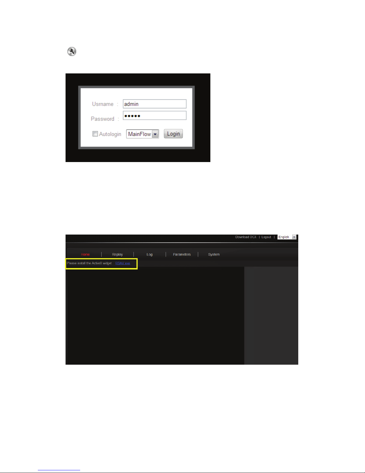
After entering Camera User Interface from DIGITUS Plug&View website through setting icon
, please key in “admin” for the Username and “admin” for the Password to login.
At the first viewing of the IP camera, the browser will prompt the users to install the OCX
component.
Note: If the users didn’t install the ‘OCX’ before, please click the link on the page: ‘Please
install the ActiveX widget RSAV.exe’. Or directly in the upper right corner to download OCX
After the download installed directly, refresh or re-login the IE interface. Then the IE will go to
default page and show the preview image.
Page 6

6
5. Go to “Parameter” => “Network”. Select the WiFi button and the SSIDs of your available
Wireless router or Access point will pop-up on the screen. Please select the SSID you
want to connect to and key in the password if it is encrypted. Press “OK” to apply the
changes.
Page 7

7
Close the camera user interface window and unplug the Ethernet cable. Now you can
access the camera wirelessly via Plug&View APP or through
http://login.mydigitus.net
4 Change Device Name
Go to Settings and click Config button to lead to a Modify page for each camera. You
may change the name to any desired description.
Page 8

8
5 Tool bar description
Tool bar is located on the up-right-side of each IP cam media screen to
foster an easy management at your preference.
5.1 Light Signal
Green Signal
When you read the green light that means the IP cam is online and on air, therefore, its
video is successfully displayed on the screen.
Yellow Signal
When you read the yellow light that means the IP cam is online but not yet on air,
therefore, its video is not displayed on the screen.
Red Signal
When you read the red light that means the IP cam is offline, therefore,
the screen is blank.
5.2 Full Screen
Full screen button is to lead you to a new screen layer where the video is displayed in
full screen for the clearer vision and event play back function.
5.3 Live View & PTZ
“Live view” button is to view the selected IP cam’s media in a timely manner. You may also
select to view the different camera’s media from the “camera list” displayed on the
left-hand side of the screen. Click the arrow buttons and to select more IP cams
from the list.
Click located on the top-right hand side of the screen to exit the full screen function, or
click located on the right-bottom side of the screen to get back to the matrix view page.
You may click to reload the live view media if you encounter problem getting it. Each
selected camera’s configuration can be accessed by clicking on the right-bottom side of
the screen.
Page 9

9
When the selected IP cam supports PTZ function, its PTZ control panel will be displayed for
you to manage camera angle on the right-bottom side of the screen. Otherwise, the panel will
be displayed in grey to indicate it is not functioning. Each angle adjustment requires one click
to make.
5.4 Play Back
“Play back” function is only supported when IP cam is embedded with SD card for media
recording. All the recorded events can be retrieved from the blue mark displayed in timeline.
Page 10

10
All recorded events are stored and marked in the timeline as in blue tag. You may manage to
view them in different time length: by clicking hour, day or week located on the top-left hand
side of the timeline.
The detailed recorded clips will be displayed when mouse over on the blue tag and the tag
turned to be in orange. Then you can select a specific clip to review at your wish.
While playing back the selected media clip, you may also manage it to be stopped, paused,
move one clip forward or backward from the media control panel. Or, you may also drag the
progress bar cursor to the specific playing point at your preference.
Setting
Setting button is to lead you to that specific IP cam’s setting web UI.
Mute
Mute or un-mute buttons are used to control whether the users would like to hear
the voice receiving via camera or not.
Refresh
Refresh button is for you to refresh or reload the IP cam video.
Remove
Remove button is the button for you to remove this specific IP cam media in Overview
page.
Page 11

11
5.5 Google Drive - Cloud Storage
On mydigitus.net website, after login with your registered account, please go to “Setting” page.
Please press the “Google Authentication” button on the top left corner and accept to use “Google
Drive” as your cloud storage by clicking “OK”.
Then the Google Drive login website will pop-up. Please login your Google Drive account and
password if you already have an existing account. Otherwise, please “SIGN UP” for a new account.
After entering your Google account, please press “Allow access” to permit video backup from the
camera to Google Drive. Then this window will close automatically.
Page 12

12
So this cloud storage feature is making a copy of your video files stored in the Micro-SD card to
Google Drive. That means the motion triggered recorded videos or scheduled recording videos
stored in the local storage can also be found and even play online on cloud storage. Please login to
your Google Drive and select the recorded videos (rtv) file to view the videos online. In order to have
this cloud storage feature, please make sure the Micro-SD card is inserted to the camera and
formatted.
6 Camera User Interface
6.1 Menu Description
The camera UI has 5 functions (Home, Replay, Log, Parameter & System).
6.1.1 Home
This page is showing the Live-view of the camera.
Page 13

13
Under Home, you can also control Pan & Tilt (only DN-16036 model) as well as the video
settings such as brightness, contrast and saturation.
6.1.2 Log
Log is used to record down all the events happened such as motion detection or alarm.
You can select the date and press the search button to list out all the logs for this date.
To playback the event, you can press “View” for the recorded video.
6.1.3 Parameters
Network, Video Parameters, DDNS & UPnP, Video Cover, Motion Detection, CMOS Sensor,
OSD Set and Alarm Set can be configured here.
Network
Under Network setting, you can select between Fixed IP or DHCP modes. Different ports for
HTTP, RSTP and RCFG can also be configured here if port forwarding setting is necessary.
Page 14

14
Video Parameters
Users can set the resolution, bit rate, type, frame rate, image quality, etc. of the main stream
in the Video Parameters Setting.
The user can select the Main flow and Minor flow. Main flow is mainly used if high resolution
video streaming is required with using Computer and Notebook where there are higher CPU
power comparing to Mobile devices. Minor stream is normally used if mobile phone access is
desired. Both of the main and sub stream support Constant Bit Rate (CBR) and Variable Bit
Rate (VBR) mode
You can select 5 levels of image quality setting: Very High, High, Normal, Low and
Very Low.
Page 15

15
6.1.4 Video Cover
This menu allows users to cover the privacy area with color block. The camera maximum
supports 4 color blocks area. Click on the video image and drag the mouse, there will be a
green block, that is, the cover region. Click OK. Choose the Video Cover option as ‘Off’, click
‘OK’ to close all the configurations.
6.1.5 Motion Detection
Please select “On” to enable motion detection. Use the mouse cursor to click the region for
motion detection. The high-lighted color region is the motion detection region. The Motion
Detection Level ranges from 0 to 5 where the smallest value indicates the highest sensitity.
Typical suggestion is Level 3. The Motion Detection Gap indicates how many frames later,
the motion detection should be re-triggered.
Page 16

16
6.1.6 OSD Set
Users can set Time, Device Name and two other extended information on screen.
The color and position of the characters are also adjustable.
6.1.7 Alarm Set
There are three types of alarm settings: Motion Detection, External Alarm and Time
Recording. Time recording allows you to select the desired time for continuous recording to
the Micro-SD card. For example, you can set the normal work time of Monday to Friday, 9am
to 6pm by high-lighted the block with blue colors. High-lighting with color means during this
period, the recording will be always ON. Please enable “Record” by ticking the box. Please
press “OK” to apply the changes.
Page 17

17
For motion detection setting, please tick the box to enable this feature. Please go to “Motion
Detection” setting first if the detection area and the sensitivity have not yet been set as
shown in the earlier section of this document. Please high-light the time blocks with blue
color for the motion detection period. Please enable “Record” to enable motion triggered
recording to the Micro-SD card.You can also setup the email notification in the event of
motion detection as shown below.
Snapshot is also possible in the event of motion detection by enable “Capture”.
Together with snapshot, you can also setup the email notification with attachment of this
captured picture as shown below. Please press “OK” to apply the changes.
Upload to FTP is also available. Please enable FTP and press FTP set to input the FTP
information. This feature will backup all of the recorded videos and pictures from the
TF card to the FTP.
Page 18

18
6.2 System
System Setting includes Local Settings, Time Settings, System Tools, User and Device
Information.
6.2.1 Local Settings
Login options and video streaming options, select the type of stream video files and capture
pictures and save path set in the Local Settings.
6.2.2 Time Settings
Manual Setting, Sync with computer time, Sync with NTP and Time Zone
are optional. Users can choose the method they want.
Manual Setting: Please key in the time and date manually.
Sync with computer time: IP camera time will be auto synchronous with the users’ PC.
Sync with NTP: Input domain name or IP address of the NTP server.
Time Zone: Users can choose the time zone according to their location.
Page 19

19
6.2.3 System Tools
System Tools includes Reboot, Factory default,SD format, View Picture on SD-card, update
Backup configuration file, Update configuration file and System.
System update is used for firmware upgrade.
 Loading...