

Page 1

LCD KVM Module
Quick Installation Guide
DS-72212 DS-72213 DS-72214
DS-72216 DS-72217
Introduction
This is a KVM module, which must work with LCD KVM console (17” DS-72210/19” DS-72211)
The modular design and installation of the product series, you can freely replace the actual
needs of the KVM components to facilitate the free combination of different applications.
According to the module type can be divided into 2 categories: VGA cable type,
CAT5 connection type. 1, 8 and 16 port KVM choices are available.
Page 2

Package Contents
Model Number DS-72212 DS-72213 DS-72214 DS-72216 DS-72217
KVM module Type 1 Port 8 Port 16 Port 8 Port 16 Port
KVM USB/PS/2
Cable 1.8m
USB KVM Cat5
Dongle
Install screw No x 2pcs x 2pcs x 2pcs x 2pcs
Quick Installation
Guide
No x 8pcs x 16pcs No No
No No No x 8pcs x 16pcs
x 1pcs x 1pcs x 1pcs x 1pcs x 1pcs
KVM module Introduction
Single port KVM module cable (DS-72212)
LCD Console Connector DB37P
Computer-side VGA + USB (Type A) + PS/2 keyboard (purple) + PS/2 mouse (green)
It is needed if no 8/16 KVM module connected to LCD console.
Page 3

8 Port VGA KVM module (DS-72213)
8 port VGA Rear View (with IP module)
16 Port VGA KVM module (DS-72214)
16 port VGA Rear View (with IP module)
8 Port Cat5 KVM module (DS-72216)
8 port CAT5 Rear View (with IP module)
16 Port Cat5 KVM module (DS-72217)
16 port CAT5Rear View (with IP module)
KVM module Installation
Before Install KVM module, you should have LCD console ready
For example DS-72211 showing below
Page 4
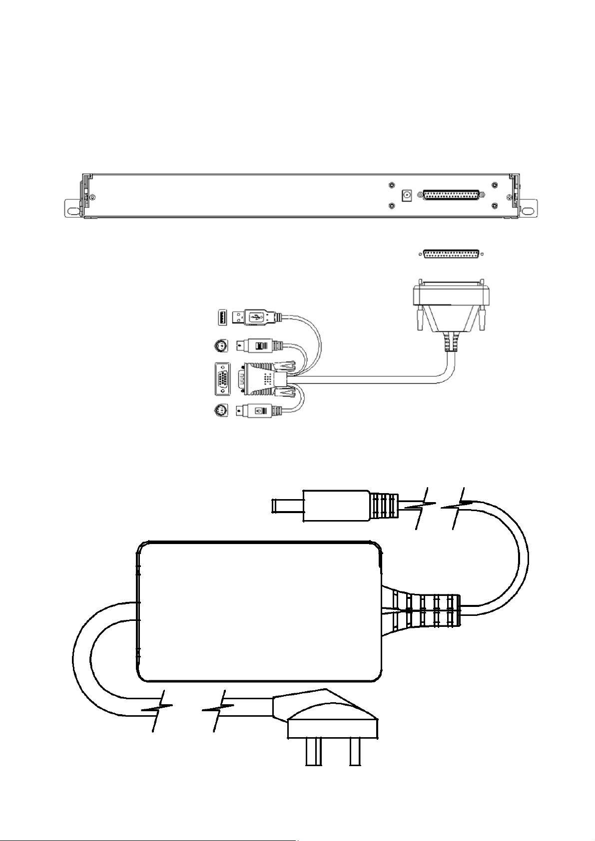
Single Port LCD KVM Cable
(DS-72212)
VGA Single port LCD KVM
1. Connect DB 37PIN to LCD Console
2. Connect VGA and USB or PS/2 to a computer or a KVM switch
(1 Port KVM module cable: DS-72212)
3. Connect Power adapter
Page 5
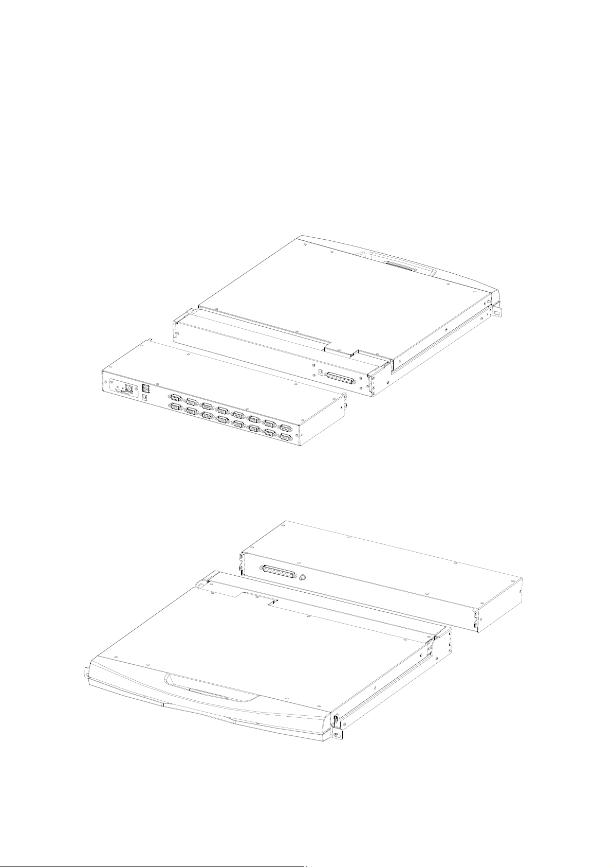
KVM Module Installation
(DS-72213, DS-72214)
Please refer to the figure for loading and unloading operations:
1. Now put this series of products on the appropriate operating platform, ready for
Screwdriver tools for subsequent use of removable screws.
Add the KVM module and the captive screws on the side brackets as shown to install the
KVM module into the front LCD Console.
2. Please be careful to connect between the KVM module & LCD console. During the
installation or removing, it may damage the connection interface and equipment
function failure.
3. Connect Power adapter
4. Turn on computers
Page 6

CAT5 KVM Module Installation
(DS-72216, DS-72217)
Connect DB 37PIN to LCD Console, similar to VGA KVM module.
To install a Cat 5 KVM module, refer to the following diagrams and do the following:
1. Plug your USB keyboard and mouse into the USB console port if 2nd console needed.
2. Use a set of CAT5e/6-wire connectors to plug into any available CAT5 Port on the
switch. Maximum CAT cable length support 60m.
3. Plug a CAT5e/6-wire connector into the CAT5 connector on the Dongle module of
the KVM, and connect the corresponding VGA video connector, USB or PS/2
connector of the Dongle cable to the corresponding port on the PC.
4. Plug the power adapter supplied with this package into the AC power source, and
plug the other end of the power adapter into the power jack on the switch.
5. Connect the network cable to the IP port of the IP module. (Optional)
6. Turn on the computer.
Note:
1. Make sure that all plugs are connected to the same group of KVM
connection port jacks (all connected to Port1, or all connected to Port2).
2. The IP module is an optional module of the product. If the product you
purchased does not include the module, please ignore the related operation
in Step 5.
3. Before using the IP module, please make the appropriate configuration and
network debugging after the access to the network you want to connect, or
may fail to connect because of normal remote control. (Refer to the manual
of the IP module product manual for how to use and debug the IP module.)
4. LCD KVM conversion module is divided into two types: PS/2 and USB port,
you can connect your computer to choose the appropriate conversion
module to use.
5. Make sure you are connecting to a computer and LCD KVM switches have a
good grounding protection altogether, or it may produce a video display
problems
6. For display problems caused by transmission distance, electromagnetic
interference, common ground, etc. It is recommended to use Category 6
shielded network cable to connect and try to improve the display effect
Page 7
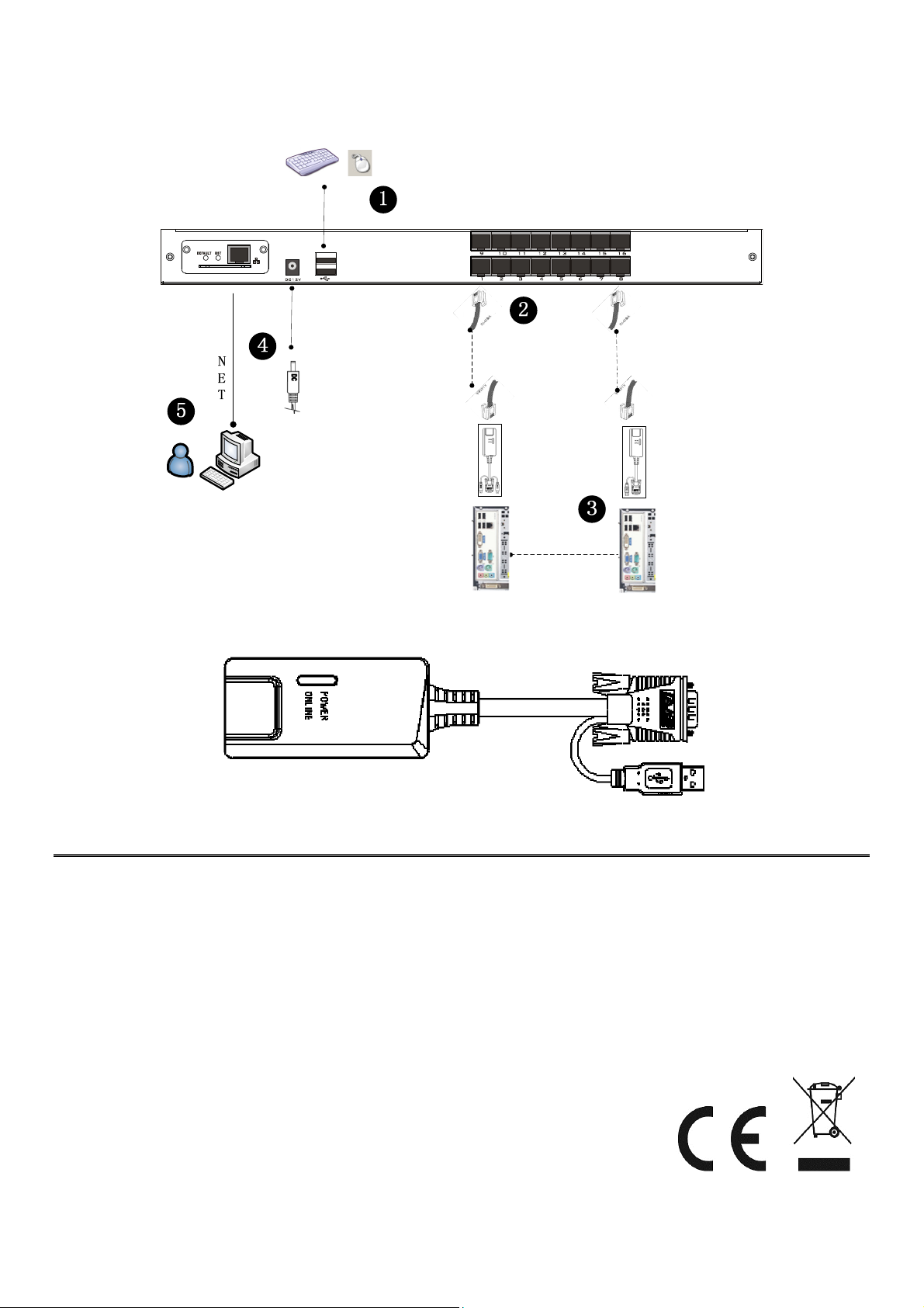
Connection Diagram
(Dongle module)
(Maximum cable length 60m)
This is a Class A product. In home environment, this product may cause radio interference. In this case, the
user may be required to take appropriate measures.
Hereby Assmann Electronic GmbH, declares that the Declaration of Conformity is part of the shipping
content. If the Declaration of Conformity is missing, you can request it by post under the below mentioned
manufacturer address.
www.assmann.com
Assmann Electronic GmbH
Auf dem Schüffel 3
58513 Lüdenscheid
Germany
 Loading...