

Page 1

DisplayPort over IP EXTENDER
Manual
DS-56200 • DS-56201
Page 2

1. Introduction
Thanks for purchasing the DS-56200 DisplayPort over IP Extender (DS-56201
receiver only). We recommend that you read this manual thoroughly and retain for
future reference.
Features
The DisplayPort over IP Extender allows you to extend video and audio up to 100
meters distance between source or computer and monitor or projector. With the builtin video and audio signals enhancement, you can gain the best video resolution
quality and audio stereo sound while listening, and no any additional software
needed. Furthermore, the installation and operation are easily more than expected.
With using in extension facilities of video and audio, this product, The DisplayPort
over IP Extender, delivers worthy of performing efficiency and value-added.
Support DisplayPort 1.1
With Expandable Receiver, each Receiver Unit with cascade function enables to
link two other (2) Receiver Units consecutively extending another 100m distance,
and continue expanding corresponding to custom demand as likely
Cascade/Tree Chain web architecture spread.
Uses easy to install, inexpensive CAT. 5e/6 cables
Each pair (TX & RX) extends the signals up to 100m (330 feet) using 1-to-1
connection
Uses network environment for transmission
Supports video high resolution up to 1920x1080@60Hz, Full HD 1080p
HDTV compatible (720p, 1080i, 1080p)
Supports Stereo 2.0
Cascaded-chainable receiver up to 10 layers
Supports RS-232 (Serial)
IR (Infrared remote) enabled
Support local DisplayPort monitoring port
Each receiver (remote) links cascade-chainable 2 receivers
Support VGA(DS-53201) and HDMI (DS-55201) receiver
Rack mountable
Page 3
Package Contents
DS-56200
DisplayPort Extender Transmitter x 1
DisplayPort Extender Receiver x 1
Power Adaptor DC 5V x 2
User Manual x 1
DS-56201
DisplayPort Extender Receiver x 1
Power Adaptor DC 5V x 1
User Manual x 1
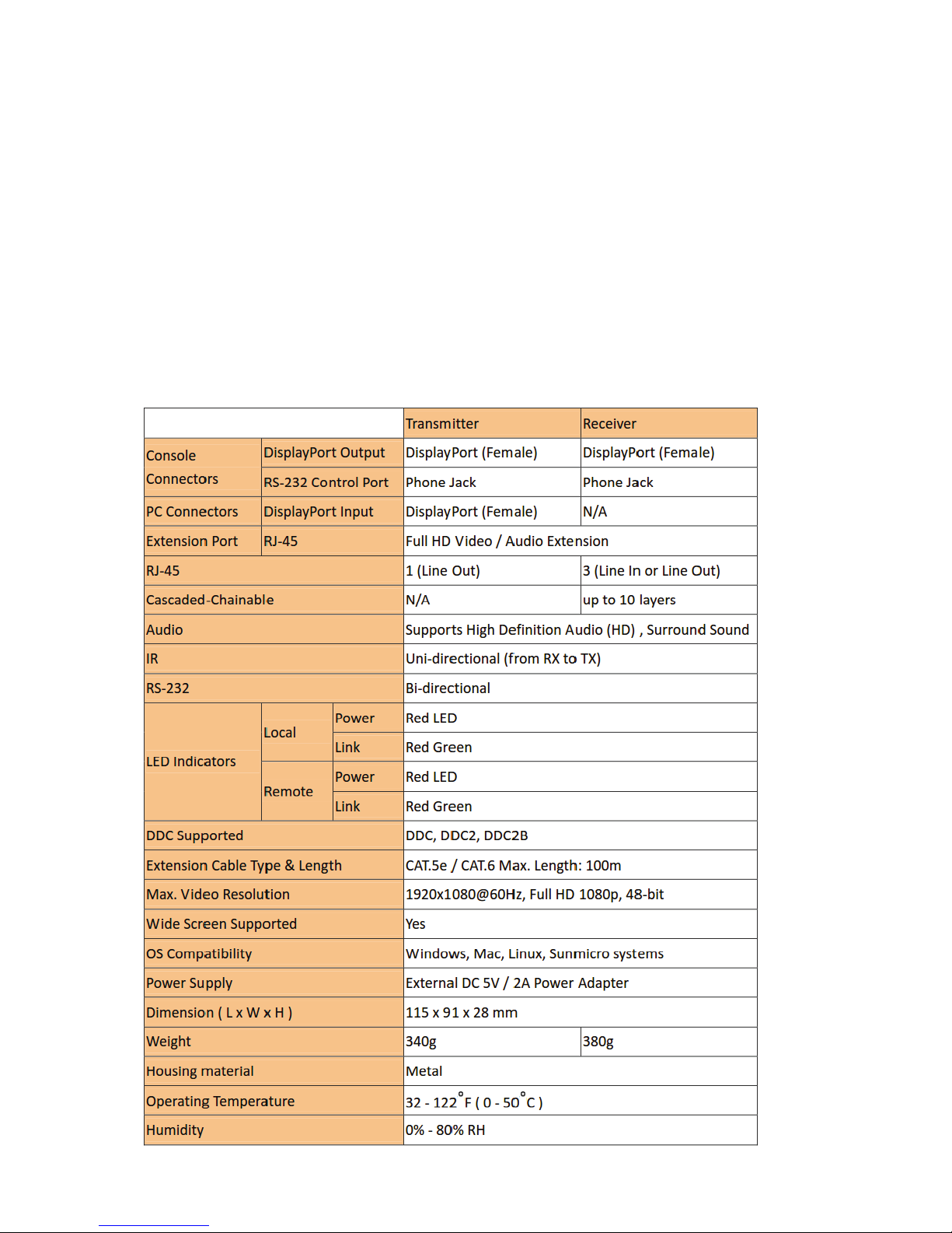
Specification
Page 4

2. Detail and Diagram
Detail Picture
Page 5
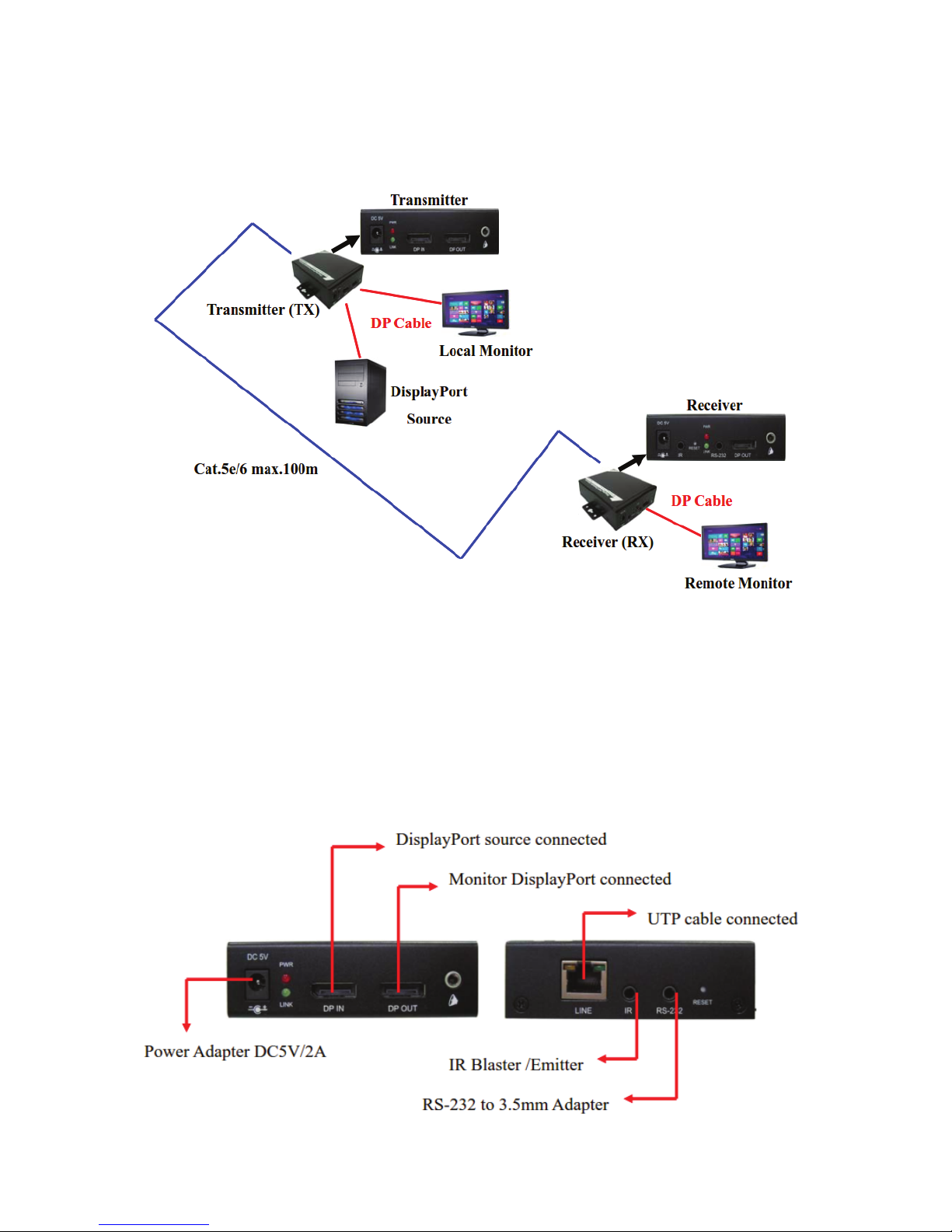
Application Diagram
1-to-1 connection
Transmitter Installation
Connect UTP Cable to Transmitter, please use CAT.5e/6 Cable
Connect the IR Blaster Emitter cable or RS-232 to 3.5mm adapter to the
Transmitter Unit IR Port or RS-232 control port if necessary.
Connect Transmitter with DisplayPort cable to DisplayPort connector of
DisplayPort source
Connects Transmitter with DisplayPort cable to DisplayPort connector of
Monitor if necessary
Plug DC 5V/2A power adapter
Page 6

Receiver Installation
Connect UTP Cable to Receiver, please use CAT.5e/6 Cable
Connect the IR Receiver cable or RS-232 to 3.5mm adapter to the Receiver
Unit IR Port or RS-232 port if necessary
Connect Receiver with DisplayPort cable to DisplayPort connector of Monitor
Plug DC 5V/2A power adapter
Page 7
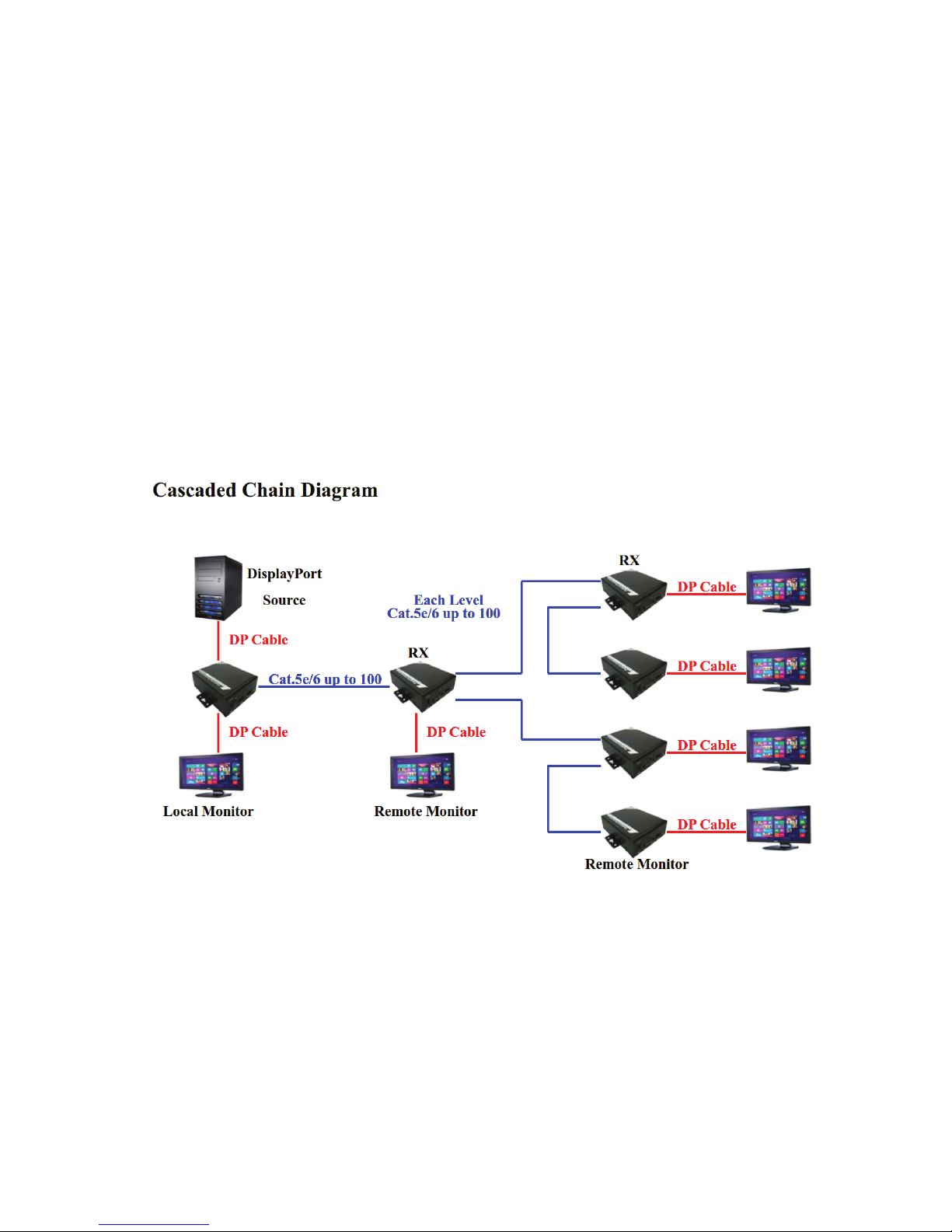
Cascade Chain Connection
1. Plug DC 5V/2A power adapter.
2. Use UTP Cable connected with Receiver to link the other two (2) Receiver Units
consecutively to extend another 100m distance, the cable connector node is to
connect to Receiver LINE1 or LINE2 or LINE3 port (RJ45), as long as the LINE
port is not occupied, and user can continue expanding corresponding to custom
demand as likely Cascade/Tree Chain web architecture spread.
3. Connect the IR Receiver cable or RS-232 to 3.5mm adapter to the Receiver Unit
IR Port or RS-232 port if necessary.
4. Connect Receiver with DisplayPort cable to DisplayPort connector of Display
Monitor.
Each Receiver with three (3) Line port, one is used for source input, and the other
two are used for expanding source to other receivers. User can choose any LINE port
as source input at random, and use the other two LINE port for expanding source to
next tier receiver as long as the LINE port is not occupied.
Page 8
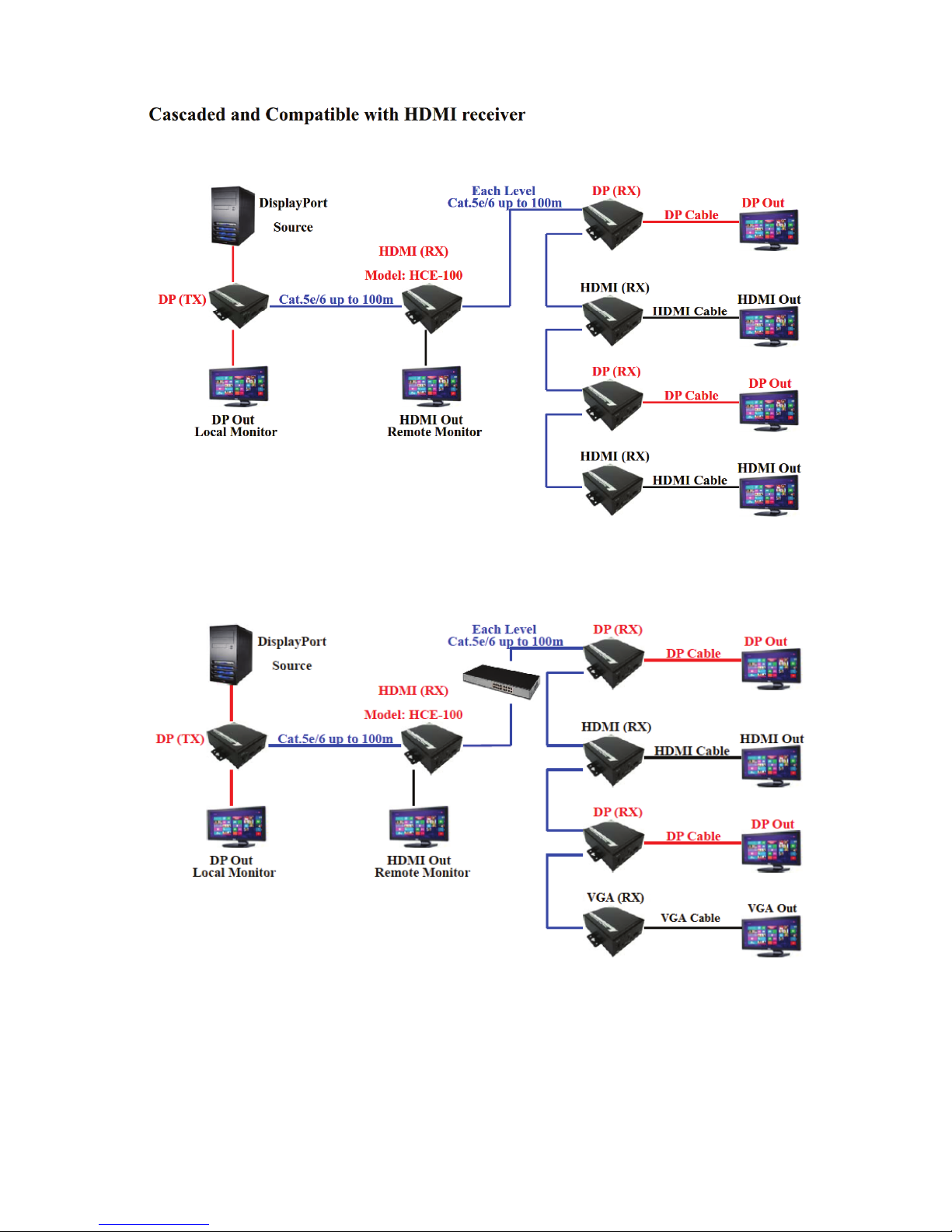
Cascaded and mixed with VGA / HDMI / DisplayPort
Page 9

IR Bypass Function Connection
Connect the IR Transmitter (or Emitter) cable to the IR Connector on the
DisplayPort
Transmitter Unit (TX)
Connect the IR Receiver cable to the IR Connector on the DisplayPort
Receiver Unit (RX)
Place the IR Eye of the IR Receiver cable near the Remote Controller
Place the IR Blaster of the IR Transmitter cable near the device that intend to
be controlled by the Remoter controller
RS-232 Bypass Function Connection
Connect the device, such as a PC, projector…etc, to the RS-232 port of the
DisplayPort Transmitter Unit or DisplayPort Receiver Unit via a RS-232 to
3.5mm adatper
Connect the controlling device to the RS-232 port of the DisplayPort Receiver
Unit or DisplayPort Receiver Unit via a RS-232 to 3.5mm adapter
Page 10
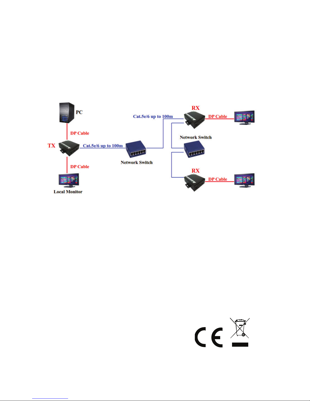
Hub Extend Function Connection
The maximum distance between each tier could be up to 100 meters long, while
this could be extended through Network Switch. User can add one Network
Switch to extend another 100 meters.
The more Network Switches, the longer distance extended. The number of
Network Switches is as many as user want.
Note: In case of incorrect installation and improper use in a residential area, the interference to radio
devices and other electronic devices could be caused. It is recommended to use the device where
applicable with shielded cables (also shielded with networking products of cable Category 5e and
higher). The device was tested to comply with the limits for Computer and IT accessories of Class A
according to the requirements of EN 55022.
Warning: This product complies with the test class A - It may be used in the living area but could
cause radio interference; in this case, it may be demanded by the operator to take appropriate
corrective action at his/her own expense. Declaration of Conformity: The device meets the EMC
requirements according to EN 55022 class A and EN 55024 for ITE category with external or built-in
power supply to meet the requirements of EN 61000-3-2 and EN 61000-3-3 according to the EMC
Directive 2004/108/EC. The declaration of Conformity can be requested by post at the following
manufacturer address.
www.assmann.com
ASSMANN Electronic GmbH
Auf dem Schüffel 3
58513 Lüdenscheid
Germany
 Loading...