

HDMI over IP EXTENDER
Manual
DS-55200

1. Introduction
Thanks for purchasing the DS-55200 HDMI over IP Extender. We recommend
that you read this manual thoroughly and retain for future reference.
Features
The HDMI over IP Extender allows you to extend video and audio up to 100 meters
distance between source or computer and monitor or projector. With the built-in video
and audio signals enhancement, you can gain the best video resolution quality and
audio stereo sound while listening, and no any additional software needed.
Furthermore, the installation and operation are easily more than expected. With using
in extension facilities of video and audio, this product, The HDMI over IP Extender,
delivers worthy of performing efficiency and value-added.
With Expandable Receiver, each Receiver Unit with cascade function enables to
link two other (2) Receiver Units consecutively extending another 100m distance, and
continue expanding corresponding to custom demand as likely Cascade/Tree Chain
web architecture spread.
• Uses easy to install, inexpensive CAT. 5e/6 cables
• Each pair (TX & RX) extends the signals up to 100m (330 feet) using 1-to-1
connection
• Uses network environment for transmission
• Supports video high resolution up to 1920x1080@60Hz, Full HD 1080p
• HDTV compatible (720p, 1080i, 1080p)
• Supports Stereo 2.0
• Cascaded-chainable receiver up to 10 layers
• Supports RS-232 (Serial)
• IR (Infrared remote) enabled
• Support local HDMI monitoring port
• Each receiver (remote) links cascade-chainable 2 receivers
• Rack mountable
Package Contents
1. HDMI Extender Transmitter x 1
2. HDMI Extender Receiver x 1
3. Power Adaptor DC 5V x 2
4. User’s Manual x 1
Specification
Transmitter Receiver
Console Connectors
PC Connectors DisplayPort Input HDMI (Male) N/A
Extension Port RJ-45
RJ-45 Ports
Cascaded-Chainable
Audio Supports Stereo 2.0
IR Uni-directional (from RX to TX)
RS-232 Bi-directional
LED Indicators
DDC supported Yes
Extension Cable Type & Length Cat.5e / Cat.6, max. length: 100m
Video resolution
Wide screen supported Yes
OS compatibility OS independent
Power supply External DC 5V / 2A power adapter
Dimensions (L x W x H) 115 x 91 x 28 mm
Weight
Housing material Metal
Operating temperature 0 - 50°C
Humidity 0% - 80% RH
HDMI Output HDMI (Female) HDMI (Female)
RS-232 Control Port Phone Jack Phone Jack
Full HD Video / Audio Extension
1 (Line Out) 3 (Line In or Line Out)
N/A up to 10 layers
Local Power
Local Link
Remote Power
Remote Link
Red LED
Green LED
Red LED
Green LED
HDMI:1920x1080@60Hz, Full HD 1080p, 48-bit
VGA: 1600 x 1200@60Hz
340 g 380 g
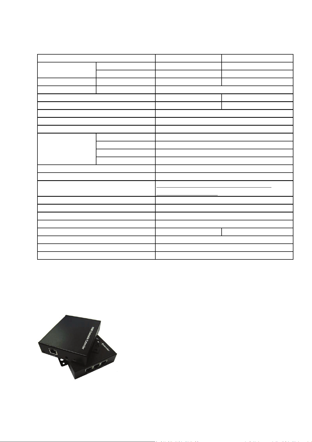
2. Detail and Diagram
Detail Picture

Transmitter (TX)-Front Transmitter (TX)-Rear
: Connected to Power Adapter DC 5V/2A
1
2: Power LED (Solid Red when power present)
3: Link LED (Solid Green when link present)
4: RS-232 control port
5: HDMI IN, connected to HDMI source
6: HDMI OUT, connected to display
7: Cat.5e/6 cable connected for data out
8: IR Blaster /Emitter
9: Reset Button
Receiver (RX)-Front Receiver (RX)-Rear
1: CAT.5e/6 cable connected for data in or out
2: CAT.5e/6 cable connected for data in or out
3: CAT.5e/6 cable connected for data in or out
4: Connected to Power Adapter DC 5V/2A
5: IR Receiver
6: Reset Button
7: Power LED (Solid Red when power present)
8: Link LED (Solid Green when link present)
9: RS-232 control port
10: HDMI OUT, connected to display

Appli
c
g
c
k
n
1-to-1
ation D
conne
iagram
tion
Usin
networ
enviro
ment

Transmitter Installation
• Connect UTP Cable to Transmitter, please use CAT.5e/6 Cable
• Connect the IR Blaster Emitter cable or RS-232 to 3.5mm adapter to the
Transmitter Unit IR Port or RS-232 control port if necessary.
• Connect Transmitter with HDMI cable to HDMI connector of HDMI source
• Connects Transmitter with HDMI cable to HDMI connector of Display Monitor if
necessary
• Plug DC 5V/2A power adapter
Receiver Installation
• Connect UTP Cable to Receiver, please use CAT.5e/6 Cable
• Connect the IR Receiver cable or RS-232 to 3.5mm adapter to the Receiver
Unit IR Port or RS-232 port if necessary
• Connect Receiver with HDMI cable to HDMI connector of Display Monitor
• Plug DC 5V/2A power adapter

Casc
a
T
c
c
o
R
e
r
e
o
a
b
o
e
e
i
c
e
v
a
e
e
a
c
s
e
r
a
e
e
o
a
a
3
s
n
w
e
m
o
c
r
h
h
S
g
k
,
p
n
s
s
e
w
t
d
e
)
p
u
e
o
.
d
e
r
a
o
a
s
w
m
o
E
e
t
u
h
e
Use U
conse
conne
is not
as likel
Each
two ar
as sou
next ti
de Cha
P Cable
utively to
t to Recei
ccupied,
y Cascad
eceiver w
used for
ce input
r receiver
n Conn
onnected
xtend an
er LINE1
nd user c
/Tree Ch
ith three (
xpanding
t random,
as long a
ction
with Rece
ther 100
or LINE2
n continu
in web ar
) Line po
source to
and use t
the LINE
iver to lin
distance
r LINE3
e expandi
hitecture
t, one is u
other rec
e other t
port is no
the other
the cable
ort (RJ45
g corres
pread.
ed for so
ivers. Us
o LINE p
occupied
two (2) R
connecto
, as long
onding to
rce input,
r can cho
rt for exp
ceiver Un
node is t
s the LIN
custom d
and the o
se any LI
nding so
its
port
mand
her
NE port
rce to
Netw
The m
could
extend
The m
Switch
rk Swit
ximum di
e extend
another 1
re Netwo
s is as m
h Exte
tance bet
d through
00 meters
k Switche
ny as us
ding
een eac
Network
.
, the lon
r want.
tier coul
witch. Us
er distanc
be up to
r can add
e extende
00 meter
one Net
. The nu
long, wh
ork Switc
ber of N
ile this
to
twork
Singl
Sourc
Extens
on

Singl
e
e
e
e
u
R
e
r
s
a
Singl
Sourc
Sourc
Extens
with M
on and
ltiple R
Receive
ceiver
s Casc
Cascad
de Chai
ed
ning

Cascaded and mixed with VGA / HDMI / DisplayPort
IR Bypass Function Connection
• Connect the IR Transmitter (or Emitter) cable to the IR Connector on the
DisplayPort
Transmitter Unit (TX)
• Connect the IR Receiver cable to the IR Connector on the DisplayPort
Receiver Unit (RX)
• Place the IR Eye of the IR Receiver cable near the Remote Controller
• Place the IR Blaster of the IR Transmitter cable near the device that intend to
be controlled by the Remoter controller

RS-232 Bypass Function Connection
• Connect the device, such as a PC, projector…etc, to the RS-232 port of the
DisplayPort Transmitter Unit or DisplayPort Receiver Unit via a RS-232 to
3.5mm adatper
• Connect the controlling device to the RS-232 port of the HDMI Receiver Unit
or HDMI Receiver Unit via a RS-232 to 3.5mm adapter
 Loading...