

Page 1
HDMI EXTENDER SET, FULL HD
Manual
DS-55100-1
The Digitus HDMI Extender Set, Full HD offers an extender solution of up
to 50 m for the highest demands. It is used to transmit digital video and
audio signals to a maximum length of up to 50 m. The highest supported
video resolution is 1080p / 60Hz. The transmitter unit features an EDID
switch, which can be used to regulate resolution and audio format of the
output signal. The transmitter also has an HDMI Loop Out Port, which
allows you to connect a local monitor. Thanks to PoC (Power over Cable)
support, it is only the transmitter unit that needs to be powered. The
package includes two bidirectional infrared units (transmitter, receiver),
which can be used for the remote control of the connected input source.
Page 2
Important Safety Notice
Please read below safety instructions carefully before installation and
operation:
1. Do not mix up the transmitter unit (TX) and the receiver unit (RX), IR
blaster extension cable and IR receiver extension cable before
installation.
2. Do not hot plug when it is working.
3. Use DC5V power supply only. Make sure specification matched if
using adapters not supplied by factory.
4. This HDMI Extender supports POE to power the receiver (Connect
power supply to the transmitter only and receiver is powered by the
Transmitter). Please note that this HDMI Extender cannot use with
switch or router.
Product Features
1. Include a transmitter unit (TX) and a receiver unit (RX), working
as a pair.
2. Support resolution is up to full HD 1080p@60Hz.
3. Use CAT6/6A/7 for long distance transmission.
4. Transmission distance up to 50 meters via CAT6 cable.
5. Uncompressed and zero latency.
6. With EDID switch for setting a very needed HDMI signal format
7. Support POE to power the receiver from transmitter.
8. Support IR pass-back for remote control source device from
receiver site easily.
9. Plug and play, without installation.
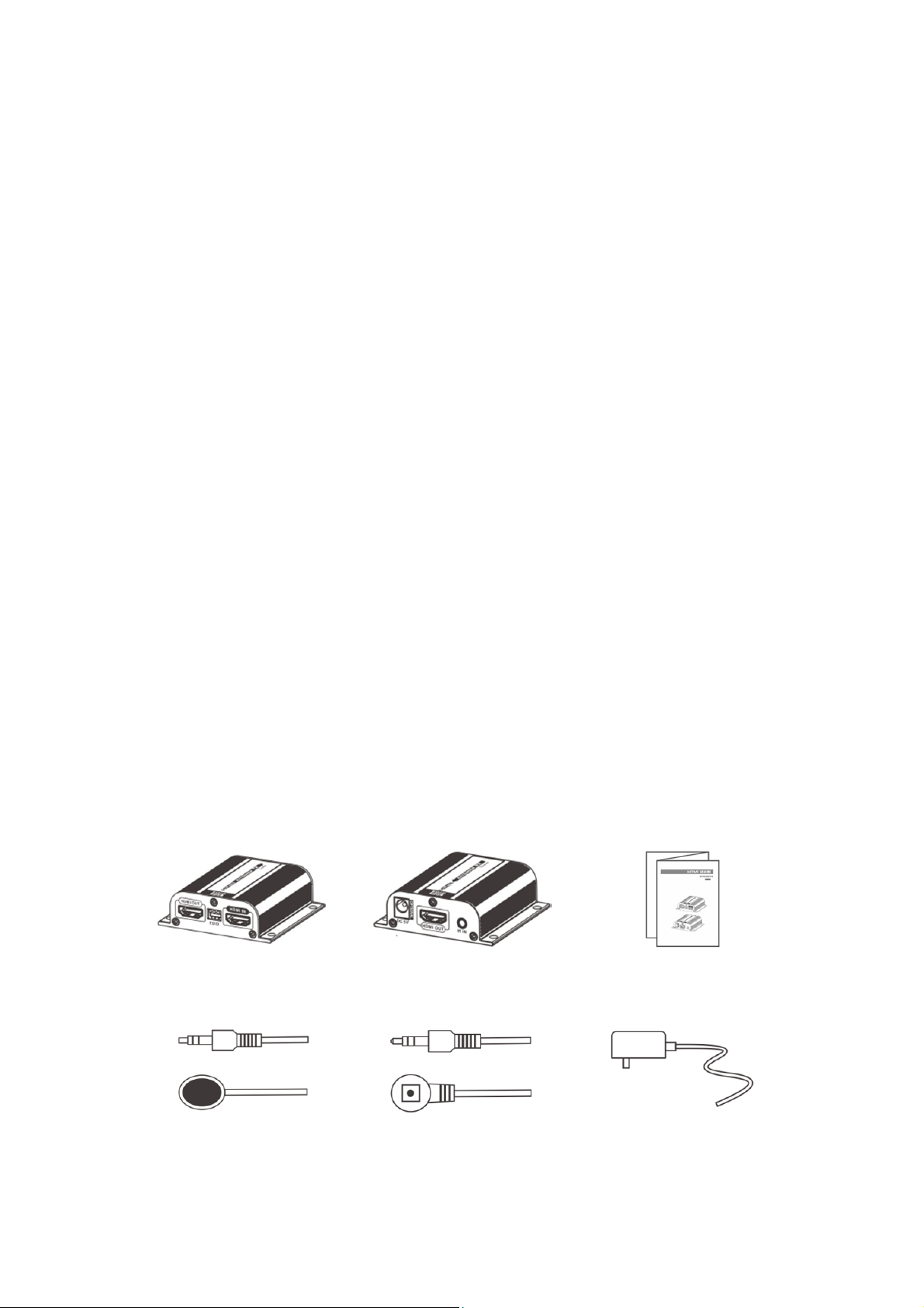
Package Contents
Transmitter unit
(Tx) × 1pcs
IR blaster extension
cable ×1pcs
Receiver unit
(Rx) ×1pcs
IR receiver extension
cable×1pcs
User manual×1pcs
Power supply×1pcs
Page 3

Specification
Part No. DS-55100-1
Technical Transmitter-TX Receiver-RX
HDCP compliance 1.2a
Video bandwidth 225MHz (10.2Gbps)
Video support 480I/P, 576I/P, 720P, 1080I/P, 3D
Audio support PCM, AC3, DTS
Input TMDS signal 1.2Vp-p
Input DDC signal 5V
ESD protection 8KV
EDID support yes
loop-out on TX one HDMI loop-out on TX
POE support RX powered by TX
IR pass-back yes
IR frequence
Range (KHz)
Mechanical Transmitter-TX Receiver-RX
Housing Metal enclosure
Dimensions 71.6 x 66.9 x 22.6mm 71.6×66.9×22.6mm
Net weight 70g 70g
Fixedness wall-mounting case with screws
Power supply 5V2A
Consumption ≤3W ≤3W
Operation
temperature
Storage temperature -20~70°C
Relative humidity 0~95%(non-condensing)
20-60KHz
0~40°C
Installation Requirements
1. HDMI source device (computer graphics card, DVD, PS3, HD
monitoring equipment etc.).
2. HDMI display device like SDTV, HDTV, and projector with HDMI port.
3. UTP/STP CAT6/6A/7 cable, follow standard IEEE-568B.
(It is suggested to use shielding network cable to avoid interference
based on CE requirement)
Page 4

Penal Description
1. Transmitter unit (TX)
① IR signal output to connect with
blaster extension cable
② RJ45 signal output
③ HDMI signal indicator led: it lights on
all the time when HDMI signal input,
flashes when no signal input
2. Receiver unit (RX)
① DC 5V power input
② HDMI signal output
④ Reset button
⑤ DC 5V power input
⑥ HDMI signal output
⑦ EDID switch
⑧ HDMI signal input
③ IR signal input to connect with IR receiver extension cable
④ LENGTH: for adjusting to the length of network cable
⑤ RJ45 signal input
⑥ RJ45 indicator led: it lights on all the time when HDMI signal
transmission, flashes when no signal transmission
Page 5

Installation and Connection
1. How to make a CAT6/6A/7 network cable Follow the standard of
IEEE-568B:
1. How to make a CAT5/5E/6 network cake
Follow the standard of IEEE-568B:
1- Orange/white 2- Orange
3- Green/white 4- Blue
5- Blue/white 6- Green
7- Brown/white 8- Brown
2. Connection
HDMI EXTENDER RXHDMI EXTENDER RX
CAT6/6A/7 Cable
DVD
HDMI OUT
HDMI display
HDMI OUT
HDMI display
3. Connection instruction
1) Connect source device to Transmitter unit (TX), and display device to
Receiver unit (RX) via HDMI cables
2) Connect Transmitter unit (TX) and Receiver unit (RX) via network
cables (CAT6, CAT6A or CAT7)
3) Plug the power supply to Transmitter unit only, each unit will power
up then initialize itself, this HDMI extender works
Page 6

[NOTE] It is recommended to use a length range within 15~50m
network cable. If the CAT6 cable is too short, there may be no display
output because of the signal is too strong. If the CAT6 cable is too long,
the output may be with poor quality.
4. IR User Guide
4.1 IR blaster extension cable should plug in the IR OUT port of
TX(Sender) of HDMI extender, and the IR receiver extension cable
should plug in the IR IN port of the video wall controller
4.2 The emitter of IR blaster should as close as possible to the IR
receiver window of the signal source device.
4.3 Using the IR remote controller of the signal source device towards
the IR receiver (connected to the video wall controller), to remote
control source media playback.
5. EDID Setting
5.1 First of all, set the resolution mode of the source device; please
choose “AUTO” of the resolution mode. (However, when the
resolution mode of your source device is “AUTO” already, and the
output resolution (for instance, output is 720p) is still not in accord
with the resolution that set by the EDID dip switch (for instance, it is
1080p). At this time, please set the resolution of your device again to
make it in accord with the resolution that set by the EDID dip Switch
(e.g. 1080p)
5.2 HDMI source device reads the EDID information of the transmitter (TX)
and then output the Relative HDMI signal forma
5.3 It needs to power on again or reset the transmitter unit after
re-setting EDID every time
5.4 When connect a TV with loop-out HDMI port of transmitter (TX), it
can adjust EDID switch to read and save this TV’s EDID information.
When we use this function, it should connect TV with transmitter
first, and then power on these devices, so that the EDID will be read
and saved successfully. At next time, even though do not connect a
TV into the loop-out HDMI Port, the source device will output the
saved EDID information last time.
Page 7

Switch Status
EDID information
switch-1 switch-2 switch-3
0 0 0 720P@50Hz 2.1CH
1 0 0 720P@50Hz 7.1CH
0 1 0 1080i@60Hz 2.1CH
1 1 0 1080i@60Hz 7.1CH
0 0 1 1080P@60Hz 2.1CH
1 0 1 1080P@60Hz 7.1CH
0 1 1
1 1 1 Default EDID: 720P@60Hz 2.1CH
Switch UP: use the Arabic numeral “1” to represent
Switch DOWN: use the Arabic numeral “0” to represent
read and save the EDID of the
loop-out TV
FAQ
Q: No image output or audio and video display is not normal?
A: Press receiver “LENGTH” button for adjusting this unit to
self-adapt to the length of network cable.
Q: Receiver “LINK” led is flashing all the time?
A:
1) Make sure network cable connection follows the standard of
IEEE- 568B.
2) Check whether TX has HDMI signal input.
3) Reset TX&RX and reconnect.
Q: RX “LINK” led lights on all the time but no image output?
A:
1) Press RX “LENGTH” button for adjusting to the length of
network cable
2) Make sure HDMI cable is well connected with TV.
3) Make sure the network cable is fine copper wires.
Page 8

Disclaimer
The product name and brand name may be registered trademark of related
manufacturers.TM and ® may be omitted on the user manual. The pictures on the
user manual are just for reference, and there may be some slight difference with the
real products. We reserve the rights to make changes without further notice to a
product or system described herein to improve reliability, function or design.
Hereby Assmann Electronic GmbH, declares that the Declaration of Conformity is
part of the shipping content. If the Declaration of Conformity is missing, you can
request it by post under the below mentioned manufacturer address.
www.assmann.com
Assmann Electronic GmbH
Auf dem Schüffel 3
58513 Lüdenscheid
Germany
 Loading...