

Page 1
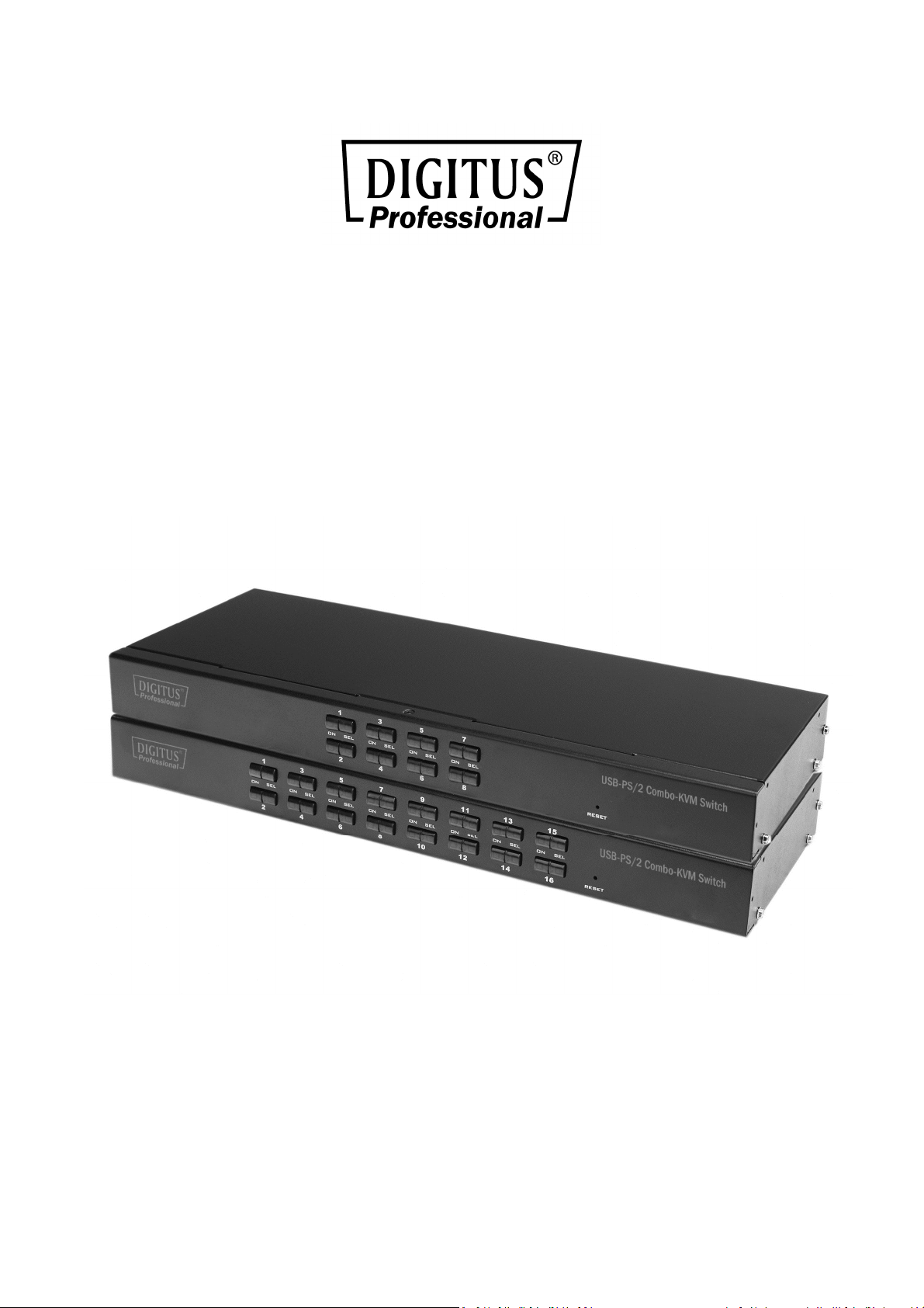
8 ports/16 ports
USB/PS/2 Combo-KVM Switch
Manual
DS-23200-2 • DS-23300-2
Page 2

PRODUCT MODEL LIST
Model Specification
DS-23200-2 8 input (USB & PS/2), 1 output (USB), Supporting cascade
& hub.
DS-23300-2 16 input (USB & PS/2), 1 output (USB), Supporting
cascade & hub.
Please check to make sure that all the components are present and that nothing
was damaged in shipping. If you encounter a problem, contact your dealer.
Read this manual thoroughly and follow the installation and operation procedure
carefully to prevent any damage to the unit, and/or any of the devices that
connect to it.
PRODUCT MODEL LIST .......................................................................................... 2
PACKING LIST ......................................................................................................... 3
OVERVIEW ............................................................................................................. 3
FEATURES .............................................................................................................. 4
HARDWARE REQUIREMENT .................................................................................. 4
Operation System ......................................................................................... 5
INTRODUCTION ..................................................................................................... 7
Front View .................................................................................................... 7
Rear View ..................................................................................................... 8
INSTALLATION ........................................................................................................ 9
Single KVM device installation ..................................................................... 9
Cascade device connection ........................................................................ 11
OPERATION ......................................................................................................... 12
OSD OPERATION .................................................................................................. 13
TROUBLESHOOTING ............................................................................................ 22
SPECIFICATION .................................................................................................... 22
SAFE GUIDE: ........................................................................................................ 24
Page 3

OVERVIEW
8 ports/16 ports USB/PS/2 KVM (Keyboard, Video, Mouse) Switches are control units
that allow access and control of up to 8 (DS-23200-2) or 16 (DS-23300-2) computers
from a single USB/keyboard, USB/mouse, and monitor console.
There are two convenient methods to access any computer connected to the
installation: (1) using the push button port selection switches located on each unit’s
front panel; (2) selecting from menus provided by the On Screen Display (OSD).
Setup is fast and easy: simply plug cables into their appropriate ports. There is no
software to configure, and no incompatible problems. It works on multiple operating
platforms (PC compatible, Sun, etc.).
There is no better way to save time and money than with a DS-23200-2/DS-23300-2
Installation: Since a single console manages all of the computers, the
DS-23200-2/DS-23300-2 setup (1) eliminates the expense of having to purchase a
separate keyboard, monitor, and mouse for each computer; (2) saves all the space
those extra components would take up; (3) saves on energy costs; (4) eliminates the
inconvenience and wasted effort involved in constantly moving from one computer to
another.
PACKING LIST
The complete 8 ports/16 ports USB/PS/2 KVM switch package consists of:
8 ports/16 ports USB/PS/2 KVM switch
Power Adapter
User Manual
Page 4

FEATURES
One console controls 8 or 16 computers
Be compatible with USB/keyboard and mouse in console and PS/2, USB
keyboard and mouse in computer
Computer selection via front panel switches and OSD
LEDs display for easy status monitoring
Auto Scan Mode for monitoring all computers
Superior video quality
Easy installation – no software required
Hot pluggable – add or remove computers for maintenance without powering
down the switch
Support Windows, Solaris etc.
HARDWARE REQUIREMENT
CONSOLE
A VGA, SVGA monitor capable of the highest resolution that you will be using
on any computer in the installation
A USB/mouse
A USB/keyboard
COMPUTER
The following equipment must be installed on each computer:
A VGA, SVGA card
PS/2, USB keyboard and mouse ports
Page 5

OPERATION SYSTEM
Operation System Version
Windows Windows 2000/XP/2003/2008/Vista/7/10
Linux RedHat 9.0 or higher
SuSE 10/11.1 or higher
Debian 3.1/4.0
Ubuntu 7.04/7.10
UNIX AIX 4.3 or higher
FreeBSD 5.5 or higher
Sun Solaris 8 or higher
Mac OS 9.0~10.6 (Snow Leopard)
Novell Netware 6.0 or higher
More operating system support, please pay attention to the latest version of the
relevant product compatibility.
Page 6
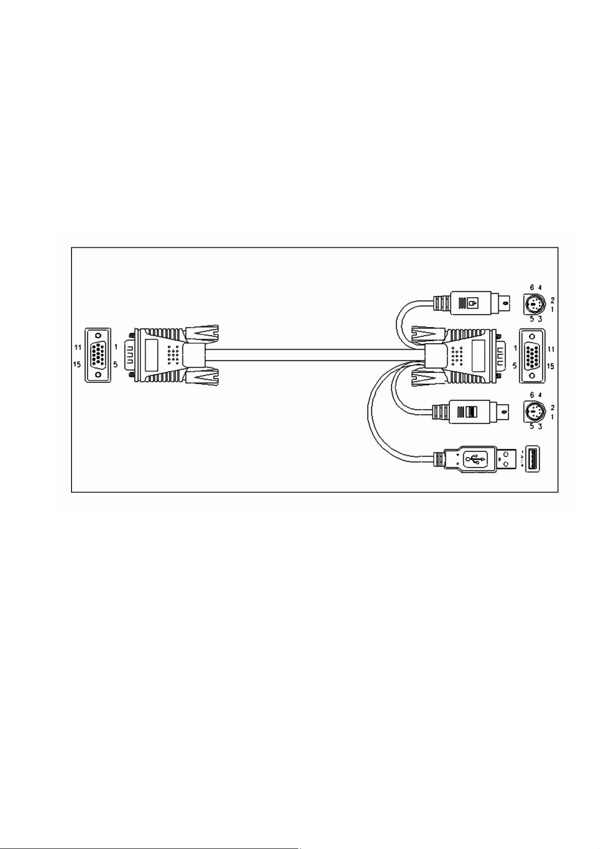
CABLE
Only customized KVM cable sets, which are specially designed to work with these
switched, may be used. To purchase DIGITUS KVM cable sets, contact your dealer.
VGA+ USB (Type A)+ PS/2 Keyboard (Purple) +PS/2 Mouse (Green)
Page 7
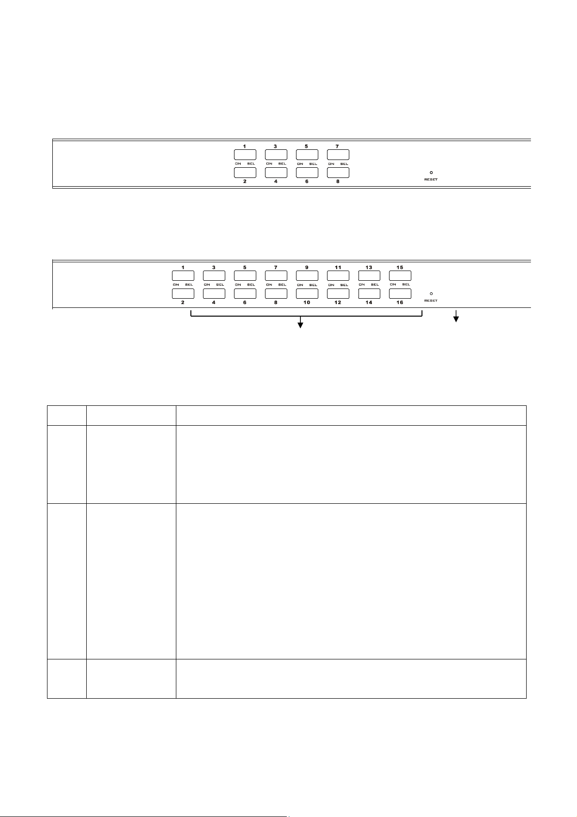
INTRODUCTION
Front View
8 ports selection switches
16 ports selection switches
1&2 3
No. Section Function
1 Port Selection
Switches
2 Port LEDs The port LEDs are built into the Port Selection Switches. The
3 Reset If KVM has no responding, plug needle or ballpoint pen into
Press a switch button to access the computer attached to its
corresponding port. The internal buzzer beeps, it means that
the switching action is performed correctly, The selected port
LED will light up as well.
upper ones are the On Line LEDs; the lower ones are the
Selected Port LEDs:
The On Line LEDs light RED to indicate that the computer
attached to the corresponding port is up and running.
The Selected LEDs light GREEN to indicate that the
computer that attached to the corresponding port is the
one that has the KVM focus.
the hole to reset KVM
Page 8
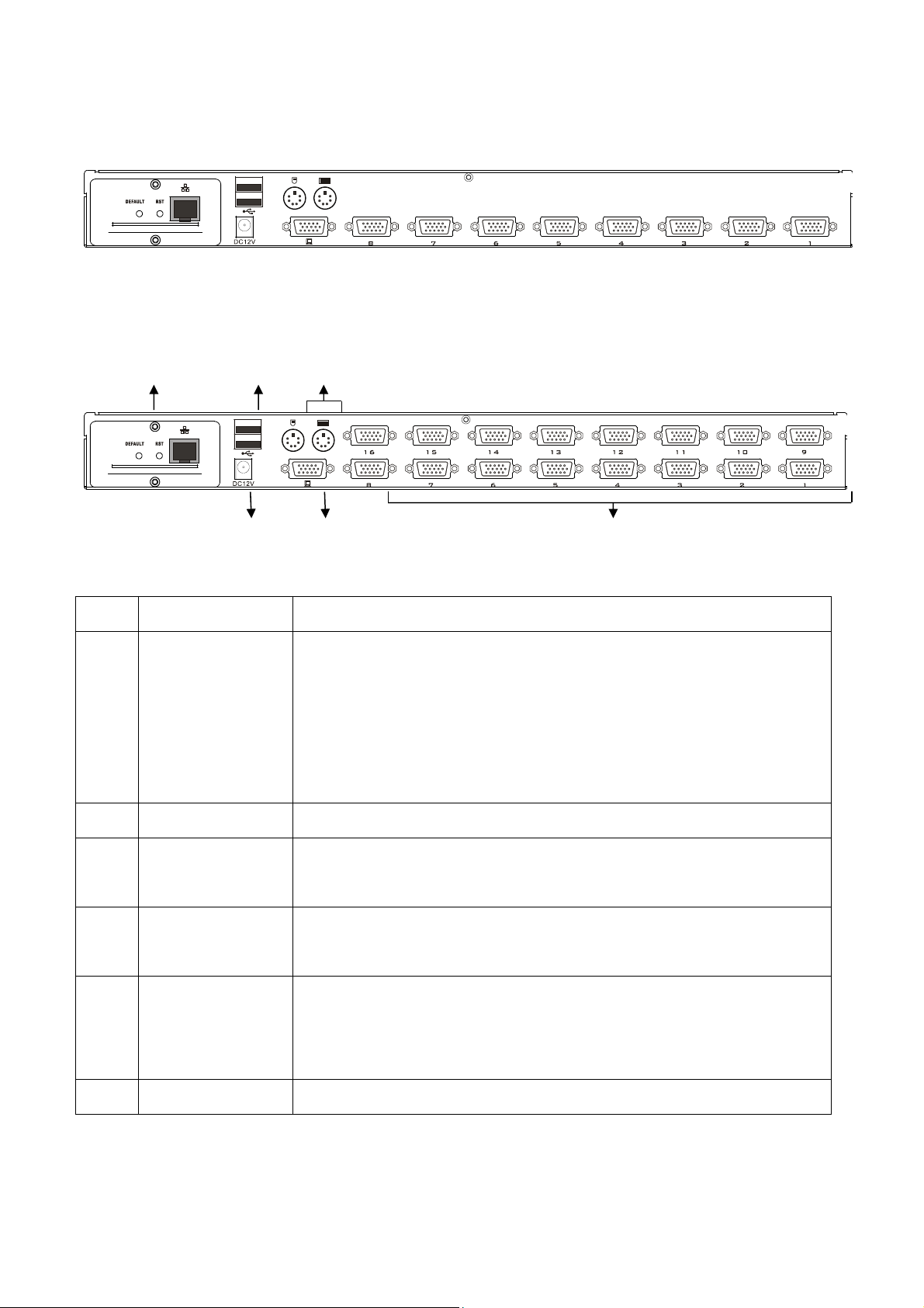
Rear View
8 port KVM rear view
5 3 4
16 port rear view
6 2 1
No. Section Function
1 KVM
Connection
Port
2 VGA port Connect the VGA cable from the control panel to this port.
3 USB Keyboard,
Mouse port
4 PS/2 Keyboard,
Mouse port
5 IP Remote
Control Part
Port to connect computer. Connect one end of the VGA
connector of the corresponding KVM cable to this, and the
other end of the keyboard connector to the port
corresponding to the PC. (Refer to the description of
"Cable" in the relevant section.)
Plug your USB keyboard, USB mouse. USB Type A
(Optional)
Plug your PS/2 keyboard, PS/2 mouse (Optional)
To provide users with remote network control. (Refer to
the instruction manual of the module product for specific
operation.) (Optional)
6 Supply hub Plug the power adapter here.
If you purchase the product does not contain IP expansion module is similar to the
product shown below.
Page 9

DS-51000-1 No IP Module Rear View
The part marked with “DS-55100-1” is the external baffle of the extended IP module,
and it needs to be removed and replaced to install the IP module.
INSTALLATION
Single KVM device installation
Note: Before installation, make sure that the equipment is powered off. To prevent
damage to the equipment during installation, make sure that all the devices installed
are well grounded.
To install a single-level KVM, refer to the following online diagrams (numbered in the
order of steps on the online graph) and operate as per bellowing:
1. Plug your USB keyboard, mouse, or PS/2 keyboard and mouse into the USB or
PS/2 console port on the rear of the switch.
2. Connect the VGA monitor's video signal cable to the VGA console port and turn
on the power.
3. Plug the VGA connector into the VGA port of any available VGA port on the
switch by using a set of KVM cables corresponding to the product model.
4. Connect the corresponding VGA video connector, USB or PS/2 connector of the
KVM cable to the corresponding PC port.
5. Plug the power adapter supplied with this package into the AC power supply,
and plugs the other end of the power adapter into the power jack on the
switch.
Page 10

6. Connect the network cable to the IP port of the IP module. (Optional)
7. Turn on the computer.
Note:
1. Make sure all plugs are connected to the same set of KVM port jacks (all on port 1,
or all on port 2).
2. The IP module is an optional module of the product. If the product you purchased
does not contain the module, please ignore the related operation in Step 6.
3. Before using the IP module, please make the corresponding configuration and
network debugging, and then connect to the network you want to connect.
Otherwise, the IP module may not be able to control normally because of the
connection failure. (Refer to the manual of the IP module product manual for how
to use and debug the IP module.)
USB OR PS2
Net
Page 11

Cascade device connection
This product can be cascaded to increase the number of controlled devices,
combined with IP remote control mode can be flexibly used in a variety of user
environment requirements.
USB OR PS2
Net
Net
Page 12

The cascade mode, it’s the same method of keyboard, mouse and computer
connections as stand-alone connection, this part will not repeat them, the
number part of the description is as follows:
1. A cascaded KVM switch can be connected in two ways by using a USB KVM
cable or a PS/2 KVM cable, Connect to the upper-level switcher.
2. The number of computers connected to each level can be free to increase or
decrease according to your needs.
Important Note: This cascade mode is divided into two levels, you need to set the
two levels of the OSD menu hot-key for two different hot-key combination,
Otherwise the cascaded KVM hotkey cannot be activated (All cascaded KVMs are
nd
belong 2
settings.)
level. Please refer to the OSD chapter for details on the OSD Hot Key
OPERATION
HOT SWAP:
The DS-23200-2/DS-23300-2 supports hot plugging. Components can be removed
and added back into the installation by unplugging and replugging their cables from
their respective ports without the need to shut the switch down. For hot plugging to
work properly, the following procedure must be observed:
Hot Swap CPU Ports:
When to plug or unplug the cable from the port, the cable must be plugged back to
the same port it removed
NOTE: The console section does not support hot plugging of PS/2 mouse and
keyboard.
Page 13

POWER OFF AND REBOOT:
If it becomes necessary to power off one of the KVM unit, before starting it back up
you must do the following:
1. Shut down all the computers that are attached to the unit
Note: If the unit is operating under external power, unplug the power adapter
cable.
2. Wait 10 seconds, then plug the power adapter back and power on all computers
PORT SELECTION:
The DS-23200-2/DS-23300-2 provides two methods to obtain instant access to any
computer in your installation: manual and OSD.
Manual:
Simply press the appropriate port selection switch on the DS-23200-2/DS-23300-2’s
front panel. After pressing the switch, the selected LED lights will indicate that the
port has the KVM focus.
OSD:
OSD (On Screen Display) provides a menu driven interface to handle the computer
switching procedure to provide instant access to any computer on the installation.
OSD operation is discussed below
OSD OPERATION
OSD OVERVIEW:
The On Screen Display (OSD) is used to handle all computer control and switching
procedures. All procedures start from the OSD main menu. To pop up the main menu,
tap the [ALT] twice.
Note: You can optionally change the hotkey to the [Ctrl] key, in which case you would
tap [Ctrl] twice.
Page 14

If OSD menu is set as “console locked”, you must input password each time the main
menu appears. If no password has been set, just press [Enter] to show main menu.
Note: There are two passwords in OSD. One is user password which is initially empty.
And the other is factory password which is “admin”.
OSD menu interface is shown as below:
Note: OSD always starts in List View, with the highlight bar at the same position it was
in the last time it was closed.
OSD NAVIGATION:
To dismiss OSD, press [Esc].
To move up and down through the list one line at a time, use the Up and Down Arrow
Keys. If there are more list entries than what can appear on the main screen, the
screen will scroll.
To activate a port, move the highlight bar to it then press [Enter].
After selecting a port, the OSD menu automatically disappear and a blue tip window
appears to indicate the port currently selected.
Page 15

OSD MAIN SCREEN HEADINGS:
Heading Explanation
PN This column lists the port numbers for all the CPU ports on the
installation. The simplest method to access a particular computer
is to move the highlight bar to it, then press [Enter].
QV If a port has been selected for Quick View scanning, an arrowhead
symbol displays in this column to indicate so.
PC The computers that are powered on and are on line have an
arrowhead symbol in this column to indicate so.
NAME If a port has been given a name, its name appears in this column.
OSD FUNCTIONS:
OSD functions are used to configure and control the OSD. For example, you can:
rapidly switch to any port; scan selected ports only; limit the list you wish to view;
designate a port as a Quick View Port; create or edit a port name; or make OSD
setting adjustments.
F1 GOTO:
GOTO allows you to switch directly to a port either by keying in the port’s name or its
port number. To use NAME method, move highlight bar to “NAME”, press [Enter],
input name of a port, then press [Enter] to confirm. To use PN method, move
highlight bar to “PN”, press [Enter], input port number, and then press [Enter] to
switch. If the port number is invalid, it will remind the user to input again.
To switch to other BANK, move highlight bar to “BANK”, press [Enter], input bank
number, and then press [Enter] to switch to the specified bank. If the bank is invalid,
it will remind the user to input again.
Note: When keying name, if there is a matching name, the matched name will appear
on the screen, just press [Enter] to switch to that port.
To return to main menu, press [Esc].
Page 16

F2 SCAN:
The SCAN function can automatically scan from current selected port, the scan
interval can be set by users. When scanning, a small window on the screen indicates
the current port number. Press [Space] to stop scanning, and the KVM switches to the
port last scanned.
F3 LIST:
The LIST function lets you broaden or narrow the scope of which ports the OSD
displays on the main screen.
Many of the OSD functions only operate on the computers that have been selected
for listing on the main screen with this function. The choices and their meanings are
given in the table below:
Choice Meaning
ALL Lists all of the ports on the installation.
QVIEW Lists only the ports that have been selected as Quick
View Ports.
POWERED ON Lists only the ports that have their attached computers
powered on.
POWERED ON + QVIEW Lists only the ports that have their attached computers
powered on and have been selected as Quick View
Ports.
QVIEW + NAME Lists only the ports that have been selected as Quick
View Ports and have name.
NAME Lists only the ports that have names
Move the highlight bar to the choice you want, then press [enter]. An icon appears
before the choice to indicate that it is the currently selected one.
After you make your choice and press [Enter], you return to the OSD main screen
with the newly formulated list displayed.
Page 17

F4 QV:
QV function can select port as Quick View. Move the highlight bar to a port, press [F4],
an icon of up triangle appears. Press [F4] again, the icon disappears.
F5 EDIT:
EDIT function creates or edits the name of a port. Press [F5], a pink edit box will
appear on the screen. Input name, and then press [Enter], the port is set a name and
it will also appear on the screen.
F6 SET:
SET function settings can be set to the administrator and the user to set the OSD
menu. The related functions and user rights related settings, such as management
settings login password, display mode, switch hotkey adjustment and so on.
Page 18

To change your settings
1. Move the highlight bar to an option; press [Enter] to enter a setting option.
2. After selecting an item, the sub-menu and the further options provided will
appear. To select it, double-click the mouse or move the selection column to the
option, and then press the [Enter] key, an icon will appear. Select the option
before to indicate that the item has been selected. The settings are described in
the following table:
Settings Function
OSD ACTIVATING HOTKEY OSD Menu Activates hotkey combination
selection settings
SWITCH HOTKEY KVM port switch hot-key combination selection
setting
CHANNEL DISPLAY MODE Port display mode selection
CHANNEL DISPLAY DURATION Select the Port form to display the Dwell Time
setting
CHANNEL DISPLAY POSITION Select the port form display location settings
SCAN DURATION Port scan dwell time setting
SET PASSWORD User login password settings
SET SUPER PASSWORD The administrator login password settings
CLEAR THE NAME LIST Clear the port name setting
RESTORE DEFAULT VALUE Reset
LOCK CONSOLE OSD Menu Password Login Function settings
Page 19

OSD ACTIVATING HOTKEY
It provides you with four hotkey combinations:
You can use the keyboard [↑] [↓] to move cursor to select, and then press [Enter]
key to save. The default is to use [ALT] [ALT] as the OSD menu start hotkey.
SWITCH HOTKEY:
It provides you with four hotkey combinations:
[SCRLL] [SCRLL] [NUM] [CTRL] [CTRL] [NUM] [ALT] [ALT] [NUM] [SHIFT] [SHIFT]
[NUM]
You can use the keyboard [↑] [↓] to move cursor to select, and then press [Enter]
key to save. The default is to use [SHIFT] [SHIFT] [NUM] as the switch hotkey.
[NUM] is the numeric keypad of the keyboard. The valid numeric range is [01] - [16].
Page 20

CHANNEL DISPLAY MODE:
This function provides three different port display modes: PN + NAME port serial
number and port name, PN only show port serial number, NAME only show port
name. You can adjust according to the actual needs of choice, the initial default PN +
NAME mode.
CHANNEL DISPLAY DURATION:
Time the tip window last.
Options are following:
3 SECOND The tip window lasts for 3seconds
ALWAYS ON The tip window always on the screen
Move the highlight bar to an option and press [Enter] to select it.
Page 21

CHANNEL DISPLAY POSITION:
Position of the tip window.
A small blue window appears on the screen. Use arrow key to move it, and then press
[Enter] to specify the position.
SCAN DURATION:
Duration for scanning one port.
Options are 3 seconds, 5 seconds, 10 seconds, 15 seconds, 20 seconds, 30 seconds,
40 seconds, and 60 seconds. Move the highlight bar to an option and press [Enter] to
select it.
OSD ACTIVATING HOTKEY: Select OSD activating hotkey
[Ctrl] [Ctrl] Set hotkey as [Ctrl] [Ctrl]
[Scroll] [Scroll] Set hotkey as [Scroll] [Scroll]
[Shift] [Shift] Set hotkey as [Shift] [Shift]
[Alt] [Alt] Set hotkey as [Alt] [Alt]
Move the highlight bar to an option and press [Enter] to select it.
SET PASSWORD: Set new password.
First enter old password, then enter new password and confirm it. The new password
is set. If error occurs, the screen will remind users.
CLEAR THE NAME LIST:
Clear the names of port list. You need to enter password to clear the names of port
list.
RESTORE DEFAULT VALUE:
Restore settings to default value.
You need to enter password to restore settings to default value.
Note: The user password will also be cleared, and the factory password will not.
Page 22

LOCK CONSOLE:
Lock the console. You cannot switch or scan after you lock the console (including
switch by push button on the panel or OSD). You need to enter password to set.
Note: After locking the console, you can also unlock the console by this option. It also
needs password verification.
TROUBLESHOOTING:
Symptom Possible Cause Action
Keyboard and/or
mouse not
responding.
OSD menu no
display.
No connection to the
computer.
KVM switch needs to be
reset.
Power supply problem. Plug power adapter to supply
Check the cable from the switch to
the computer to make sure it is
properly connected.
Press reset button on the rear panel.
enough power.
SPECIFICATION:
Function DS-23200-2 DS-23300-2
Computer
Connections
CPU Port Selection OSD Menu, Front Panel Hot-Key,
Direct 8 16
Cascade(Max) 128 256
Hot-key, Remote Control IP
Connector
(Optional)
Console
Connectors
Computer
Connectors
Power 1 x DC
IP Module Network Interface 1 x RJ45
Video 1 x VGA DB15 Female Blue
Keyboard 1 x USB Type A Female, 1 x PS2
Female (Purple)
Mouse 1 x USB Type A Female, 1 x PS2
Female (Green)
Video/Keybo
ard/Mouse
8 x VGA DB15
Female (Blue)
16 x VGA DB15
Female (Blue)
Page 23

Toggle Switch Connection Port Selection 8 x Button 16 x Button
KVM Reset 1 x Semi-embedded keys
IP Module Reset 1 x Semi-embedded keys
IP Module Default 1 x Semi-embedded keys
LEDs Computer Selection Port 8 x Green 16 x Green
On Line 8 x Red 16 x Red
IP Module Network Interface 1 x Green, 1 x Orange
Analog Mode Keyboard, Mouse USB, PS2
Video resolution (Max) 1920 x 1200 @ 60HZ Local &
Remote
Scan time interval 3, 5, 10, 15, 20, 30, 40, 60s (3s by
default)
Operating
Environment
Physical
Properties
Operating temperature -10˚C~50˚C
Storage temperature -20˚C~60˚C
Humidity 0-80%RH, No Condensation
Housing Metal
Size 432 x 155 x 44 mm
Weight 1.82KG
Page 24

SAFE GUIDE:
Please follow the directions below when installing, using and maintaining it in
order to guarantee the device to work well
When installing and operating the device, please make sure proper power
supply first, and then do other operations after it is initialized
As signal and power transfer need custom cable, please use matched cable,
unmatched cable may cause system work improperly or even damage the
device
Keep airy during operating to prevent high temperature
Keep the device away from working long in wet environment to prevent short
circuit
Please do not open the device without permission of professionals
Hereby Assmann Electronic GmbH, declares that the Declaration of Conformity is part of the
shipping content. If the Declaration of Conformity is missing, you can request it by post under the
below mentioned manufacturer address.
www.assmann.com
Assmann Electronic GmbH
Auf dem Schüffel 3
58513 Lüdenscheid
Germany
 Loading...