

Page 1
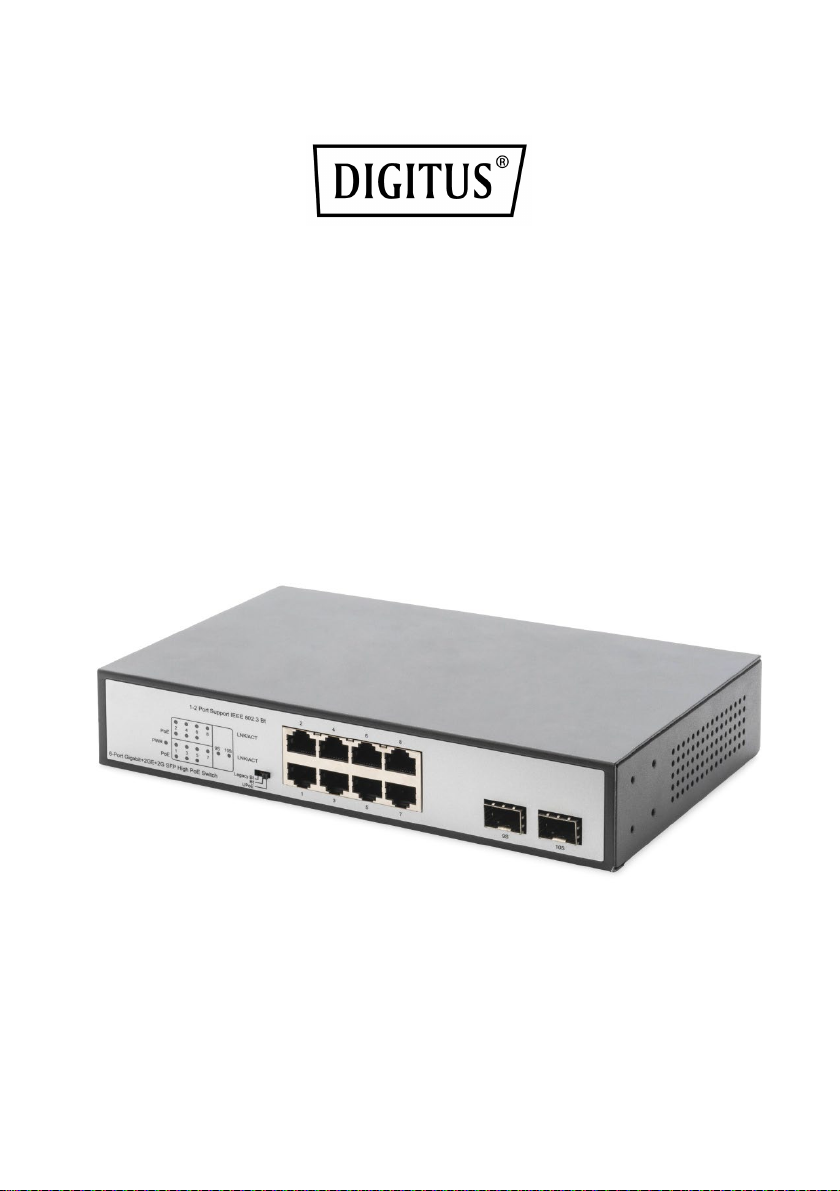
8-Port Gigabit Switch
with 6 x PoE Ports, 2 x RJ45,
2 x SFP Uplink, 802.3 af/at/bt
User Manual
DN-95140
Page 2

Contents
Introduction ............................................................................................................. 2
Package Content....................................................................................................... 3
Hardware Description .............................................................................................. 3
Front Panel ........................................................................................................... 4
Rear Panel ............................................................................................................ 4
Installation the Switch .............................................................................................. 5
Desktop Installation .............................................................................................. 5
Wall-mounted installation..................................................................................... 6
Turn on the switch.................................................................................................... 6
Specifications ........................................................................................................... 7
Introduction
The DIGITUS® 8 Port Gigabit PoE Switch provides you with a multifunctional
switch for many application scenarios. You can use all 8 ports for
conventional network devices without a PoE supply. You can use six ports for
PoE-cable network devices, two of those ports even with 90 watt (IEEE
802.3bt) per port. The remaining 4 ports support IEEE 802.3at/af devices up
to 30 watt. Two SFP uplink ports are also integrated, which you can fit with
SFP modules for fiber optic or copper technology. The gigabit standards
continue to be supported with data transfer rates of up to 1000 Mbps, auto
MDI/MDIX and auto negotiation for the RJ45 ports. The Switch also has 3
modes: Legacy BT, BT and UPoE that can be adjusted on the front side with a
DIP Switch. You can implement conventional network applications with this
Gigabit PoE Switch and also supply high-performance network devices, such
as POS systems, access control systems, a surveillance and parking-lot system
with electricity. A total budget of 180 W is provided here for PoE devices.
2
Page 3
Package Content
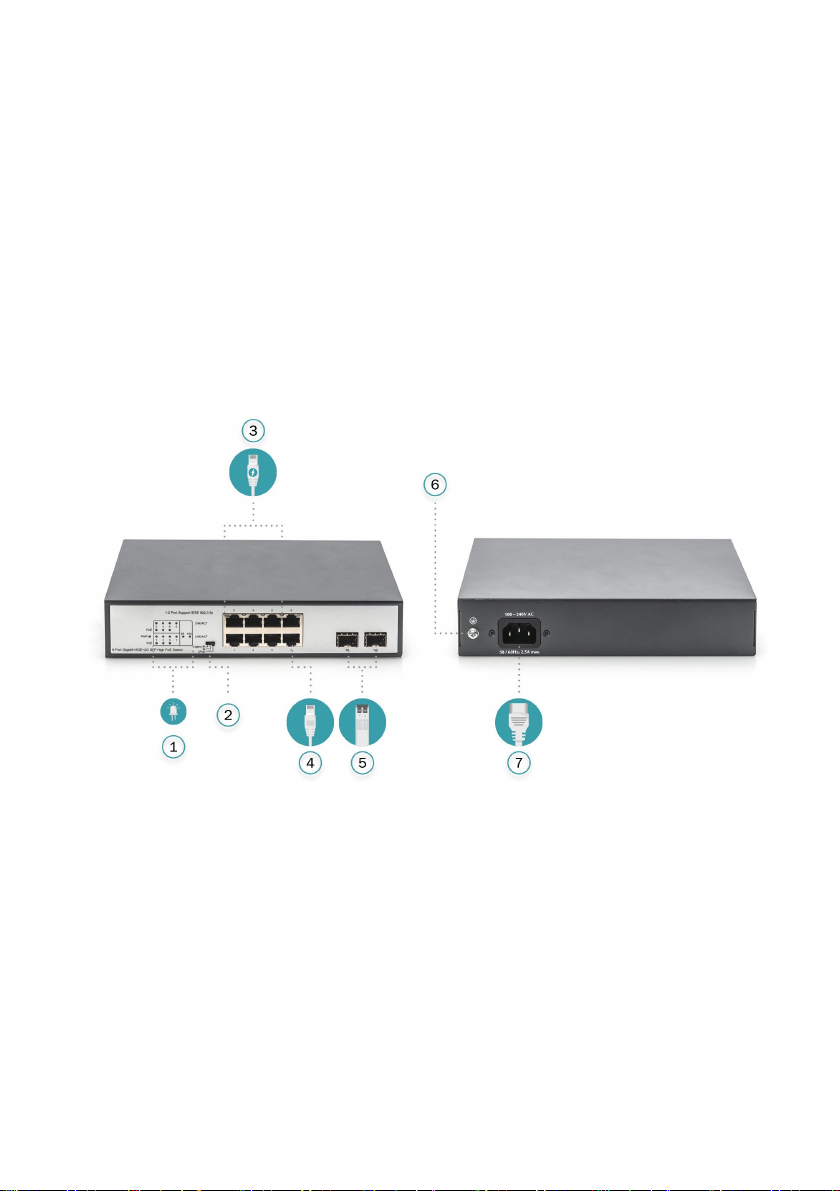
1.)
LED indicator
5.)
2x 10/100/1000 Mbps SFP Slot
2.)
DIP switch
6.)
Grounding column
3.)
6x 10/100/1000 Mbps PoE Port
7.)
Power socket
4.)
2x 10/100/1000 Mbps Port
Check the following contents of your package:
• 1x PoE Switch
• 1x User Guide
• 1x Power Cord
• 1x Accessories (4x Rubber Feet)
• 1x Mounting Bracket set
If any part is lost and damaged, please contact your local agent immediately.
Hardware Description
3
Page 4

Front Panel (left)
LED
Color
Function
PWR
Green
Off: No Power supply.
Light: Indicates the switch has power.
LINK/ACT
Green
Off: No device is connected to the corresponding port.
data over that port.
PoE
Orange
Off: No PoE powered device (PD) connected.
Blink: Indicates port abnormal power supply.
The Front Panel Consists of Ethernet Ports.
The LED indicators are also located on the panel.
DIP Switch: Control port 1-2 in different power supply modes
Note: After change the mode, there is no need to restart manually to make the
corresponding configuration take effect.
LED Indicator
Light: Indicates the link through that port is successfully
established at 10/100/1000Mbps.
Blink: Indicates that the Switch is actively sending or receiving
Light: There is a PoE PD connected to the port, which supply
power successfully.
Rear Panel (right)
The rear panel of the PoE Switch indicates an AC inlet power socket, which accepts
input power from 100 to 240V AC, 50/60HZ.
Power socket
Connect the female connector of the power cord here, and the male connector to
the AC (Alternating Current) power outlet. Please make sure the voltage of the
power supply meets the requirement of the input voltage.
Grounding column
The switch already comes with lightning protection mechanism. You can also ground
the switch through the PE (Protecting Earth) cable of AC cord or with Ground Cable.
4
Page 5
Installation the Switch
This part describes how to install your Ethernet Switch and make connections to it.
Please follow the following instructions in avoid of incorrect installation causing
device damage and security threat.
• Before cleaning the switch, unplug the power plug of the switch first. Do not
clean the switch with wet cloth or liquid;
• Do not place the switch near water or any damp area. Prevent water or moisture
from entering the switch chassis;
• Do not place the switch on an unstable case or desk. The switch might be
damaged severely in case of a fall;
• Ensure proper ventilation of the equipment room and keep the ventilation vents
of the switch free of obstruction;
• Make sure that the operating voltage is the same one labeled on the switch;
• Do not open the chassis while the switch is operating or when electrical hazards
are present to avoid electrical shocks.
Desktop Installation
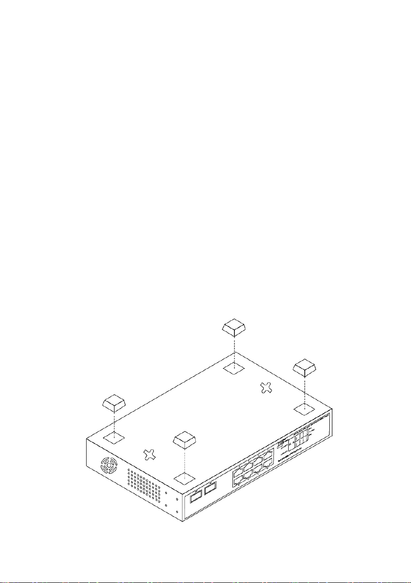
Install the Switch on a desktop, please attach these cushioning rubber feet provided
on the bottom at each corner of the Switch in case of the external vibration. Allow
adequate space for ventilation between the device and the objects around it.
5
Page 6
Wall-mounted installation
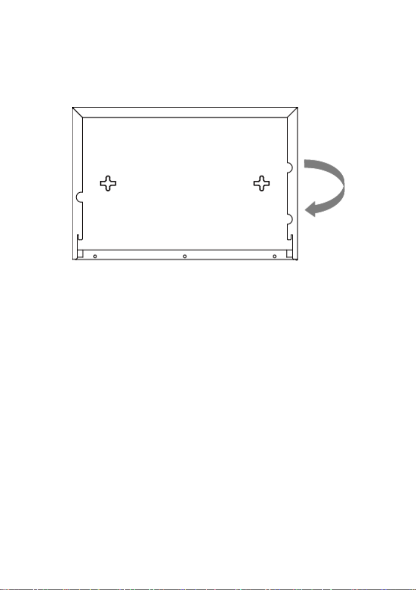
Fasten 2 screws in the wall at the distance of the switch mounting holes as shown in
the drawing. Then you can mount the switch on the wall by hooking the screws into
the mounting holes.
Turn on the switch
Please connect the AC power cord into the rear of the switch and to an electrical
outlet (preferably one that is grounded). When the switch is power on, the LED
indicators flash momentarily for one second, which represents a resetting of the
system. The Power LED indicator turns on green.
Note: Please confirm the voltage is correct before power on; otherwise the switch
will be damaged. (The power input is: 100V-240Vac, 50/60Hz.)
6
Page 7

Specifications
8-Port Gigabit Switch mit 6 x PoE-Ports, 2 x RJ45,
2 x SFP Uplink, IEEE 802.3 af/at/bt
IEEE 802.3, IEEE 802.3u, IEEE 802.3ab, IEEE 802.3i,
IEEE 802.3az
1000BASE-T: UTP category 5e cable (≤100m)
100BASE-TX: UTP category 5 cable (≤100m)
MAC Address Table
4K, Auto-learning, Auto-aging
Transfer mode
Store-and-Forward
10Base-T: 14881pps/Port
1000Base-T/X: 1488095pps/Port
Switching Capacity
20G
Dimensions (L*W*H)
220 x 150 x 44mm
Fan
Fan
Power Input
AC: 100~240V, 50/60Hz
Power Supply
190W
PoE Port
Port 1~6
PoE Power Budget
180W
Operating Temperature: 0°C ~ 40 °C (32 °F ~104°F )
Storage Temperature: -40 °C ~ 70 °C (-40 °F ~158°F )
Operating Humidity: 10% ~ 90% non-condensing
Storage Humidity: 5% ~ 90% non-condensing
Model
Standard
Network Media
Frame Forward Rate
Temperature
Humidity
IEEE 802.3, IEEE 802.3af, IEEE 802.3at, IEEE 802.3bt,
10BASE-T: UTP category 3,4,5 cable (≤100m)
100Base-TX: 148810pps/Port
This is a Class A product. In home environment, this pr oduct may caus e radi o interference.
In this case, the us er may be required to take appropriate measures.
Hereby Assmann El ectronic GmbH, declares t hat the Declaration of Conformity is part of
the shipping content. If t he Declaration of Conformity is missing, you ca n request it by post
under the below mentioned manufactur er address .
www.assmann.com
Assmann Electronic GmbH
Auf dem Schüffel 3
58513 Lüdenscheid
Germany
7
 Loading...