

Page 1
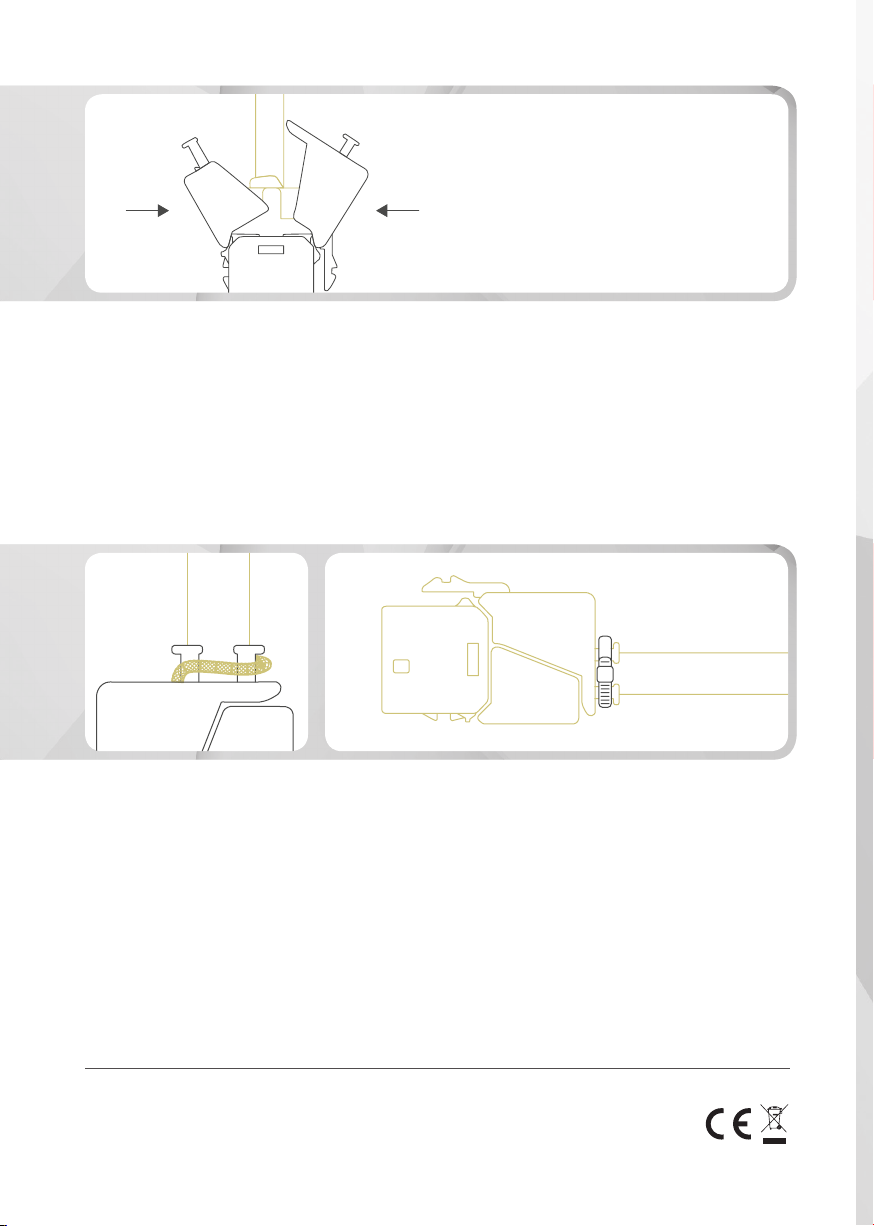
Schritt 5:
SCHLIESSEN
Schließen Sie die Außenkappe, indem Sie beide
Seiten der Außenkappe zusammendrücken, bis
es klickt.
(S/FTP)
Step 5:
LOCKING
Close the outer cap by pushing down both sides
until it clicks.
Schritt 6:
S/FTP: ERDUNG, ZUGENTLASTUNG
Verbinden Sie den Erdungsdraht/Geechtschirm
mit dem abgeschirmten Gehäuse und ziehen Sie
den Kabelbinder fest.
U/UTP: ZUGENTLASTUNG
Ziehen Sie den Kabelbinder fest.
DE - Hiermit erklärt die ASSMANN Electronic GmbH, dass sich der Artikel in Übereinstimmung mit
den Anforderung und Vorschriften der RoHS Richtlinie 2011/65/EU bendet. Die vollständige Konformitätserklärung können Sie postalisch unter der unten genannten Herstelleradresse anfordern.
EN - ASSMANN Electronic GmbH declares that the product complies with the requirements and provisions of RoHS directive 2011/65/EU. You can request the complete Declaration of Conformity by
post at the manufacturer’s address as stated below.
Step 6:
S/FTP: GROUNDING, STRAIN RELIEF
Connect the drain wire/braid shield to the shielded shell housing and tie up the cable tie and
nish.
U/UTP: STRAIN RELIEF
Tie up the cable tie and nish.
FR - Par la présente, Assmann Electronic GmbH certie que le produit est conforme aux exigences
et aux réglementations des directives RoHS 2011/65/EU. La déclaration de conformité complète
peut être demandée par post à l´adresse du fabricant ci-dessous.
ASSMANN Electronic GmbH,
Auf dem Schüffel 3, 58513 Lüdenscheid, Germany
Manufactured in P.R.C.
Page 2

MONTAGEANLEITUNG
KEYSTONE MODUL
(GESCHIRMT & UNGESCHIRMT)
ASSEMBLY INSTRUCTION
KEYSTONE MODULE
(SHIELDED & UNSHIELDED)
Page 3
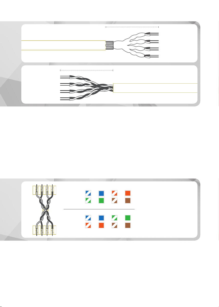
40 mm
40 mm
40 mm
(S/FTP)
1. Paar/Pair
2. Paar/Pair
3. Paar/Pair
4. Paar/Pair
1. Paar/Pair
2. Paar/Pair
3. Paar/Pair
4. Paar/Pair
(U/UTP)
Schritt 1:
S/FTP: KABELMANTEL ENTFERNEN
Entfernen Sie etwa 40 mm des Kabelmantels
und teilen Sie die Adern in 4 Paare auf.
U/UTP: KABELMANTEL ENTFERNEN
Entfernen Sie etwa 40 mm des Kabelmantels,
schneiden Sie das Kunststoffkreuz ab und teilen
Sie die Adern in 4 Paare auf.
PIN 5 4 3 6
T 568A
PIN 1 2 7 8
PIN 5 4 3 6
T 568B
PIN 1 2 7 8
Schritt 2:
VERDRAHTUNGSVERFAHREN
Führen Sie die Adern durch den Adermanager und
legen Sie diese entsprechend des Belegungsplans in die richtigen Führungen ein.
Step 1:
S/FTP: REMOVE THE CABLE JACKET
Strip approximately 40 mm of the cable jacket
and separate the wires into 4 pairs.
U/UTP: REMOVE THE CABLE JACKET
Strip approximately 40 mm of the cable jacket,
cut off the plastic cross and separate the wires
into 4 pairs.
Step 2:
WIRING CONFIGURATION
Insert the wires through the wire manager and
lay them into the correct slots, according to the
wiring diagram on the wire manager.
Page 4

max.
0,15-0,20 mm
Schritt 3:
ADERN SCHNEIDEN
Schneiden Sie die Adern bündig an dem Adermanager ab. Es wird dringend empfohlen, dass
die Spitze der Adern max. 0,15-0,20 mm herausragt.
Schritt 4:
ADERN VERPRESSEN
Anhand der Zahlencodierung erkennen Sie die
korrekte Richtung in die Sie die vorkonfektionierten Adermanager auf die Schneidklemme aufsetzen können. Drücken Sie den Adermanager auf
die Schneidklemme.
Step 3:
TRIM WIRES
Trim the wires ush with the wire manager. It is
strongly recommended that the tip of the wires
protrude max. 0.15-0.20 mm.
Step 4:
WIRE INJECTION
The numbers help you to nd the right way to
insert the wire manager onto the IDC. Press the
wire manager down onto the IDC.
 Loading...