

Page 1
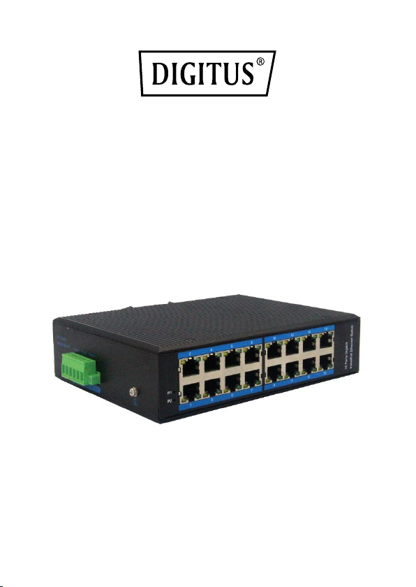
INDUSTRIAL 16-PORT
GIGABIT SWITCH,
UNMANAGED
Quick Installation Guide
DN-651129
Page 2
1. Overview
Industrial Ethernet switch with 16-Port 10/100/1000Mbps BASE-TX,
the Product meet CE, FCC, RoHS standards. DN-651129 switch has the
operating temperature of -40℃ ~ 85℃, has the super firmness can
adapt to all kinds of harsh environment, can also be conveniently
placed in the compact space of the control box. The installation
characteristics of the guide rail, wide temperature operation, IP40
protection class housing and LED indicator light make the DN-651129
a plug and play industrial grade device, providing a reliable and
convenient solution for users to network their Ethernet devices.
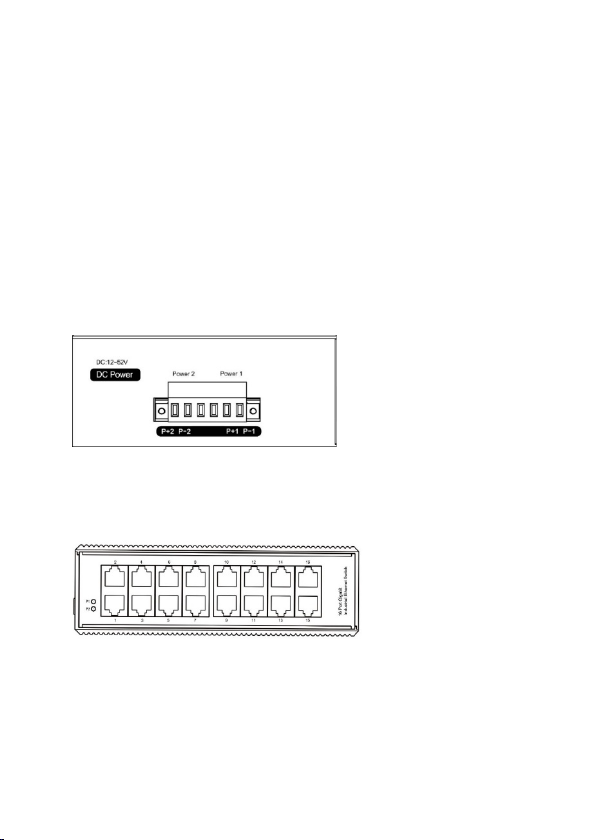
2. Switch Panel
DN-651129 Side panel:
P1 and P2 are the number of connecting terminals. P+1 and P-1 are
respectively to the positive and negative poles to be connected;
Earthing screw, used for earthing equipment.
DN-651129 Front panel:
The Yellow LED on the port is the LINK light, which is on when the
connection is established, and the data transmission is flashing. The
green LED is POE light, which is only on when the switch port is
Page 3

supplying power to PD device (this model is not to support PoE);
4.1 Standard:
IEEE802.310BASE-TIEEE802.3i
4.2 Interface:
16-Port RJ45
4.3 Work environment:
-40~85 °C (-40~185 °F)
Storage:
-40~85 °C (-40~185 °F)
4.4 Switch
Bandwidth:
56Gbps
Packet Buffer Memory:
4.1Mbit
Packet Forwarding Rate:
42Mpps
MAC Address Table:
8K
Power indicator light is on when connecting with Power.
3. Features
● The use of high quality photoelectric integration module to provide
good optical and electrical characteristics
● Ensure reliable data transmission and long working life
● Support full duplex or half duplex mode, with automatic negotiation
capability
● Network port support automatic cross identification
● Internal storage and forwarding mechanism, support a variety of
protocols
● In line with industrial operating standards, the average trouble-free
work in more than 300,000 hours
● Working power supply: DC 12-52V to provide reverse protection
● Lightning Surge Protection (Power): 5000A(8/20μs)
4. Specification
10Base-T; IEEE802.3u;100BaseTX/FX; IEEE802.3ab1000Base-T;
IEEE802.3z1000Base-X; IEEE802.3x
Page 4

4.5 Power supply:
input voltage: DC12-52V (two-way
4.6 Mechanical Characteristic:
IP40 aluminum housing
Natural colling, no fan
Weight:
0,9Kg
Measurement:
175.6 x 135 x 45.5 mm
4.7 Industrial standard:
FCC CFR47 Part 15,
conduction): 30V (cont.), 300V (1s)
Frequency range:
150kHz-80MHz
Impact:
IEC 60068-2-27
Free Fall:
IEC 60068-2-32
Vibration:
IEC 60068-2-6
power redundancy backup); Access
terminal: Phoenix terminal,
Support dual power redundancy;
Support built-in over current 4.0A
protection;
Support reverse connection
protection
DIN rail install
EN55022/CISPR22, Class A
IEC61000-4-2 (ESD): ±8kV
(contact), ±12kV (air) IEC61000-4-3
(RS): 10V/m (80~1000MHz)
IEC61000-4-4 (EFT): Power Port:
±4kV; Data Port: ±2kVIEC61000-4-5
(Surge): Power Port: ±2kV/DM,
±4kV/CM; Data Port:
±2kVIEC61000-4-6 (CS): 3V (10kHz-
150kHz); 10V (150kHz-80MHz)
IEC61000-4-16 (Common mode
Page 5
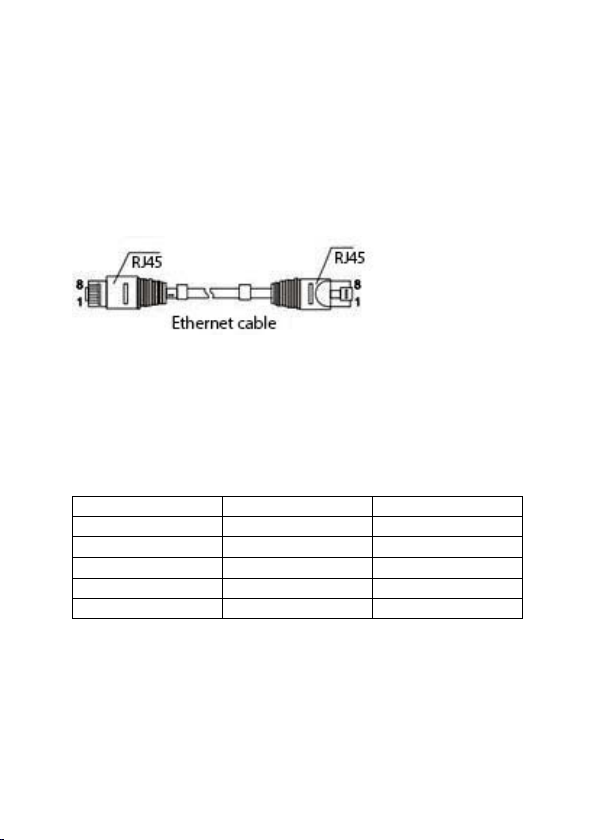
5. Interface Definition
Pin No.
MDI signal
MDI-X signal
1
TX+
RX+ 2 TX-
RX- 3 RX+
TX+ 6 RX-
TX-
4, 5, 7, 8 - -
10/100/1000Base-TX ethernet interface:
This switch provides MDI/MDI-X self-identification with cable support
on all 10/100/1000Basc-TX ports. In use, the Ethernet port of the
switch can be connected with other Ethernet terminal devices through
network cables (direct or cross).Please use Class 5 shielded twisted
pair. The Ethernet port pin definition is shown in the following figure:
RJ45 port supports automatic MDI/MDI-X operation, you can use a
straight line to connect to the PC or server, connect to other switches
or hubs. In the through line (MDI), pins 1, 2, 3, 4, 5, 6, 7, 8 correspond
to the connection; For the MDI-X port of a switch or hub, cross lines
are used: 1-3, 2-6, 3-1, 6-2, 4-7, 5-8, 7-4, 8-5.10Base-T/100Base-T (X)
pins are defined as follows:
Note: "Tx ±" refers to sent data ±, "Rx ±" refers to received data ±,
and "-" refers to unused data.
Page 6

6. LED Indicator
LED indicator
Status
Definition
Power supplying in
normal
Power supply abnormal
or no powering
Network connection in
normal
Yellow LED
flashing
Link communication in
normal
Green LED on
PoE feeding in normal
Yellow/Green
LED off
Red LED on
P1/P2
Red LED off
Yellow LED on
RJ45 indicator
No connection at port
Note: this model is not available with PoE
7. Installation caution
7.1 Installation precautions
In order to avoid damage to equipment and personal injury caused by
improper use, please follow the following precautions:
• In order to avoid damage caused by falling of the equipment,
please put the equipment in a stable environment.
• When supplying power to the equipment, pay attention to confirm
the range of power supply voltage, as well as the positive and
negative poles of the power supply, so as not to damage the
equipment by wrong operation.
• In order to reduce the risk of electric shock, ensure that the
equipment is well grounded in the working environment.
• No matter when, please do not arbitrarily remove the equipment
shell.
• When placing the switch, please avoid the area with dust and
strong electromagnetic interference
Page 7

7.2 Din rail installation
The first step is to check the grounding and stability of the guide rail:
the guide rail slot of the switch is clamped into the guide rail; The
second step: from the center to both sides of the guide rail positioning
screws in order. Step 3: Use screws to fix the mounting rail card slot
on the fixed guide groove at both ends of the guide rail to ensure that
the guide rail and the switch are fixed on the guide rail vertically and
stably.
7.3 Grounding
Fix the grounding wire to the grounding screw above the switch and
ensure good reliable connection of the grounding system.
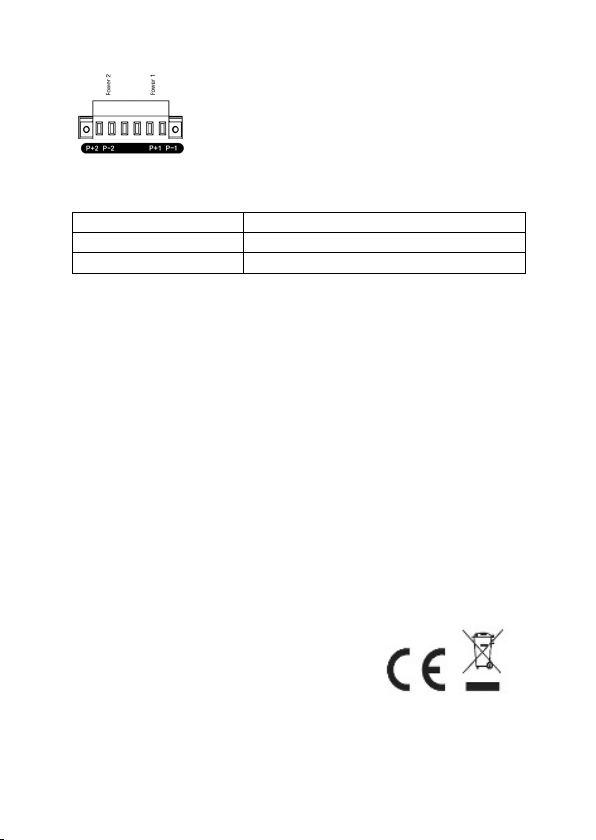
7.4 Power Connection
Insert the power cord into the specified position of the 6-core
terminal, and insert the terminal into the standard power supply inlet
(P+1 and P-1 input corresponding to the first power supply P1, and P+2
and P-2 input corresponding to the second power supply P2). The
available voltage standard of the power supply is supported from
12VDC to 52VDC
Page 8
Content
QTY
Industrial switch
1 PCS
User manual
1 PCS
www.assmann.com
Assmann Electronic GmbH
Auf dem
58513 Lüdenscheid
Germany
8. Packages
This is a Class A product. In home environment, this product may
cause radio interference. In this case, the user may be required to
take appropriate measures.
Hereby Assmann Electronic GmbH, declares that the Declaration of
Conformity is part of the shipping content. If the Declaration of
Conformity is missing, you can request it by post under the below
mentioned manufacturer address.
Schüffel 3
 Loading...