

Page 1
INDUSTRIAL GIGABIT SWITCH
DN-651126 (5-port) DN-651127 (8-port)
User Manual
Page 2

Package content
Check the following contents of your package:
Ethernet Switch x 1
User Guide x 1
Terminal block x 1
DIN Rail mount x 1
If any part is lost and damaged, please contact your local agent
immediately.
Introduction
The Industrial Gigabit Switch is designed for harsh environments where
it is exposed to moisture, temperature fluctuations and vibration. With
a temperature range of -40°C to 85°C, the Industrial Gigabit Ethernet
Switch can be used under the most adverse conditions. It ensures a
constant availability in highly sensitive areas such as transport,
production, traffic and safety monitoring. The simple plug and play
system allows the Industrial Gigabit Switch to be quickly integrated into
the respective environment. With its Gigabit connectivity, the Industrial
Gigabit Switch is a flexible, cost-effective solution for the industrial
environment.
2
Page 3
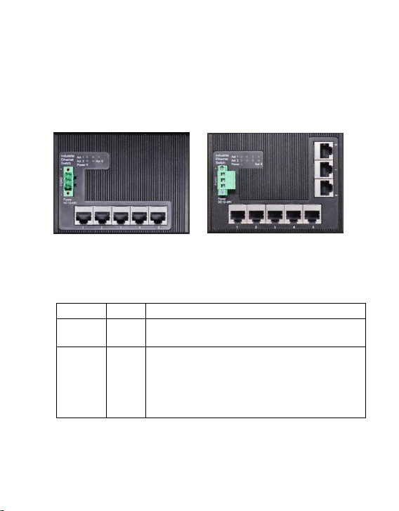
Hardware Description
DN-651126
DN-651127
LED
Color
Function
Power
Red
Off: No Power supply
Light: Indicates the switch has power
Act
Green
Off: No device is connected to the corresponding port
Light: Indicates the link through that port is
successfully established at 10/100/1000Mbps
Blink: Indicates that the Switch is actively sending or
receiving data over that port
Upper Panel
The upper panel has a standard 3-Pin industrial power input terminal
for DC power input. Also Ethernet Ports and LED indicators are located
on the panel.
LED indicator
3
Page 4
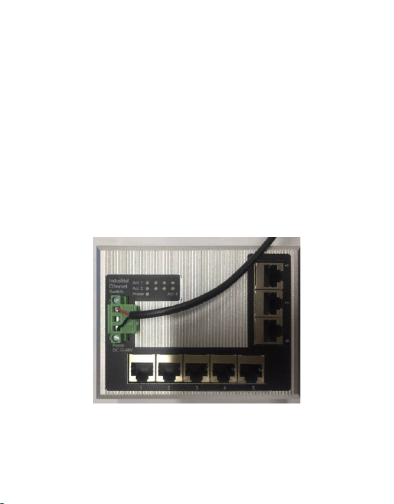
Power input
This unit provides a 3-pin terminal block. It can be operated using 12-48 V
DC power source. Always make sure your input voltage is within this
supported voltage range.
To connect power:
This unit supports two power inputs. Follow the printed polarity for
+Power-, - and ground. Connect positive wires to V+, connect negative
wires to V-, and connect a neutral wire to the ground mark.
Figure:
4
Page 5

WARNING:
Always SHUT OFF power source to connect power wire.
Any exceeded input voltage will not make this unit function and may
damage this unit.
Grounding Column
The switch already comes with lightning protection mechanism. You can also
ground the switch through the PE (Protecting Earth) with Ground Cable.
Installation of the Switch
This part describes how to install your Ethernet Switch and make
connections to it. Please follow the following instructions to avoid
incorrect installation causing device damage and security threat.
Before cleaning the switch, unplug the power plug of the switch first.
Do not clean the switch with wet cloth or liquid;
Do not place the switch near water or any damp area. Prevent water
or moisture from entering the switch chassis;
Do not place the switch on an unstable case or desk. The switch
might be damaged severely in case of a fall;
Ensure proper ventilation of the equipment room and keep the
ventilation vents of the switch free of obstruction;
Make sure that the operating voltage is the same one labeled
on the switch;
Do not open the chassis while the switch is operating or when
electrical hazards are present to avoid electrical shocks.
5
Page 6
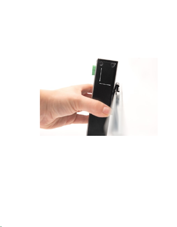
DIN-Rail Mounting
The DIN-Rail is already screwed on the Industrial Equipment. Please refer
to following figures and know how to hang the Industrial Equipment:
Step 1: Lightly press the button of DIN-Rail into the track. Install
Industrial Equipment in DIN-Rail mount.
6
Page 7
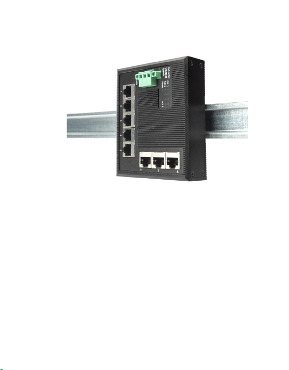
Step 2: Check the DIN-Rail is tightly on the track.
7
Page 8
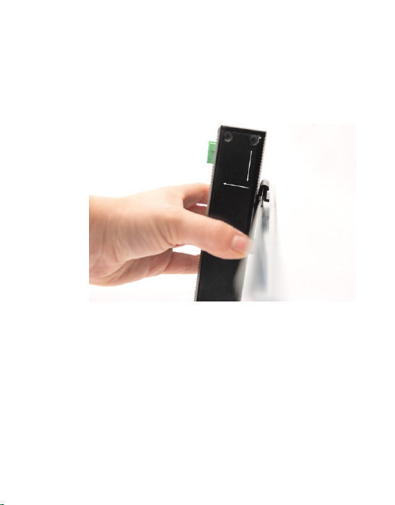
Remove DIN-Rail Mounting
Step 1: Please refer to following procedures to remove the Industrial.
Equipment from the track. Remove Industrial Equipment in
DIN-Rail mount.
Step 2: Lightly press the button of DIN-Rail for remove it from the track.
8
Page 9
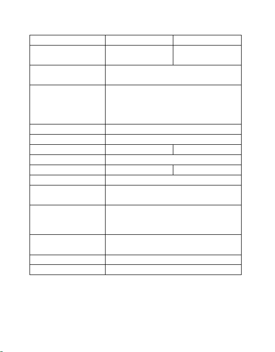
Model
DS-651126
DS-651127
Description
Industrial 5-Port
Gigabit Switch
Industrial 8-port
Gigabit Switch
Standard
IEEE802.3, IEEE802.3u, IEEE802.3ab,
IEEE802.3x, IEEE 802.3z
Network Media(Cable)
10BASE-T: UTP category 3,4,5 cable (≤100m)
100BASE-TX: UTP category 5 cable (≤100m)
1000BASE-T: UTP category 5e, 5 cable
(≤100m)
MAC Address Table
4K, Auto-learning, Auto-aging
Transfer mode
Store-and-Forward
Switching Capacity
10Gbps
16Gbps
Input power supply
DC: 12-48V
Dimensions (L*W*H)
120*110*30mm
120*110*30mm
Fan
Fanless
Temperature
Operating Temperature: -40°C ~ 85 °C
Storage Temperature: -40 °C ~ 85°C
Humidity
Operating Humidity:
5% ~ 95% non-condensing
Storage Humidity: 5% ~ 95% non-condensing
Surge Protection
Differential mode ±4KV
Common mode ±6KV
MTBF
300,000 hours
Electrostatic standard
Contact 8KV,air 15KV
9
Page 10
This is a Class A product. In home environment, this product may cause
radio interference. In this case, the user may be required to take
appropriate measures.
Hereby Assmann Electronic GmbH declares that the Declaration of
Conformity is part of the shipping content. If the Declaration of
Conformity is missing, you can request it by post under the below
mentioned manufacturer address.
www.assmann.com
Assmann Electronic GmbH
Auf dem Schüffel 3
58513 Lüdenscheid
Germany
10
 Loading...