

Page 1
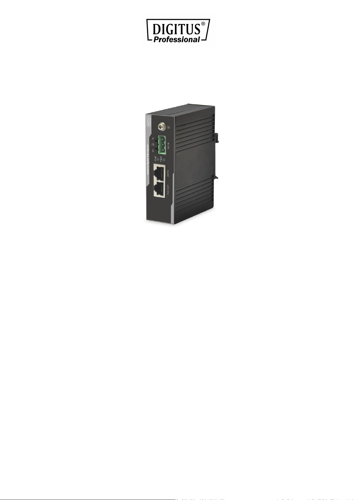
Industrial Gigabit PoE+
Injector 802.3 af/at
User Manual
DN-651112
Page 2

Table of Contents
1. Package Content .............................................................. 3
2. Product Features .............................................................. 3
3. Product Specification ....................................................... 4
4. Hardware Description ...................................................... 6
4.1 Physical Dimension .............................................. 6
4.2 Product Outlook................................................... 6
4.3 Wiring the Power Inputs ...................................... 6
5. Mounting Installation ....................................................... 8
5.1 DIN-Rail Mounting ............................................... 8
5.2 Remove DIN-Rail Mounting ................................. 9
6. Hardware Installation .................................................... 10
Page 3

1. Package Content
Upon open the box of the Industrial Power over Ethernet Injector
and carefully unpack it. The box should contain the following items:
Industrial Gigabit Power over Ethernet Injector x 1
User’s Manual x 1
If any of these are missing or damaged, please contact your dealer
immediately, if possible, retain the carton including the original
packing material, and use them against to repack the product in
case there is a need to return it to us for repair.
2. Product Features
■
Interface
2-Port RJ-45 interfaces | 1-Port PoE Out | 1-Port Data
One terminal block for power input.
■
PoE
Gigabit High Power over Ethernet End-Span PSE
IEEE 802.3at/802.3af PoE compliant
IEEE 802.3at/802.3af splitter devices compatible
Support PoE Power up to 15/30/60 Watts for PoE port
Provides DC power over RJ-45 Ethernet cable to device with
Ethernet port
Auto-detect of PoE IEEE 802.3at/802.3af equipment and
devices from being damaged by incorrect installation
Remote power feeding up to 100m
■
Hardware
IP30 Slim Type Metal Case
LED indicators for Power LED and PoE LED
Page 4

■
Industrial Case/Installation
DIN Rail Design, -40 to 75 Degree C operation temperature
PoE-enabled terminal by PSE and thus consumes energy,
such as IP Phones, network cameras and Wireless access
points, etc.
Note
PSE (Power Sourcing Equipment) is a device (switch, or hub
for instance) that will provide power in a PoE setup.
Maximum allowed continuous output power per such
device in IEEE 802.3af is 15.4W, 30W in IEEE 802.3at.
3. Product Specification
Hardware Specification
"Data" Input Port 1 x RJ-45 STP
"PoE
Interface
(Data+Power)"
Output Port
Input power
terminal block
LED Indicator
Network Cable
Data Rate 10/100/1000Mbps
Dimension (W x D x H) 103 x 78 x 32 mm
Weight 295g
Unit Input Voltage 45 ~ 56V DC
1 x RJ-45 STP
1
System: Power
PoE Port: PoE In-Use x 1
10Base-T:
UTP Cat. 3, 4, 5, up to 100m
(328ft)
100Base-TX:
UTP Cat. 3, 4, 5, up to 100m
(328ft)
1000Base-T:
UTP Cat. 5, 5e, 6 up to 100m
(328ft) EIA/TIA- 568 100-ohm
STP (100m)
Page 5

Power Consumption 60 Watts max
Number of device can be
powered
1
Installation DIN Rail kit
Enclosure IP30 Slim Type Metal Case
Power over Ethernet
PoE Standard
IEEE 802.3af
IEEE 802.3at
PoE Power Output DC 42~54V (base on Power Input)
PoE Power supply Type End-Span
Power Pin Assignment 3/6/4/5(+), 1/2/7/8(-)
Standards Conformance
IEEE 802.3 10Base-T Ethernet
IEEE 802.3u 100Base-TX Fast
Ethernet IEEE 802.3ab 1000Base-T
Standards Compliance
Gigabit Ethernet
IEEE 802.3af Power over Ethernet
IEEE 802.3at Power over Ethernet
enhancement standard
Environment
Operating Temperature -40 ~ 75 Degree C
Storage Temperature -40 ~ 85 Degree C
Humidity 5 ~ 95% (Non-condensing)
Page 6
4. Hardware Description
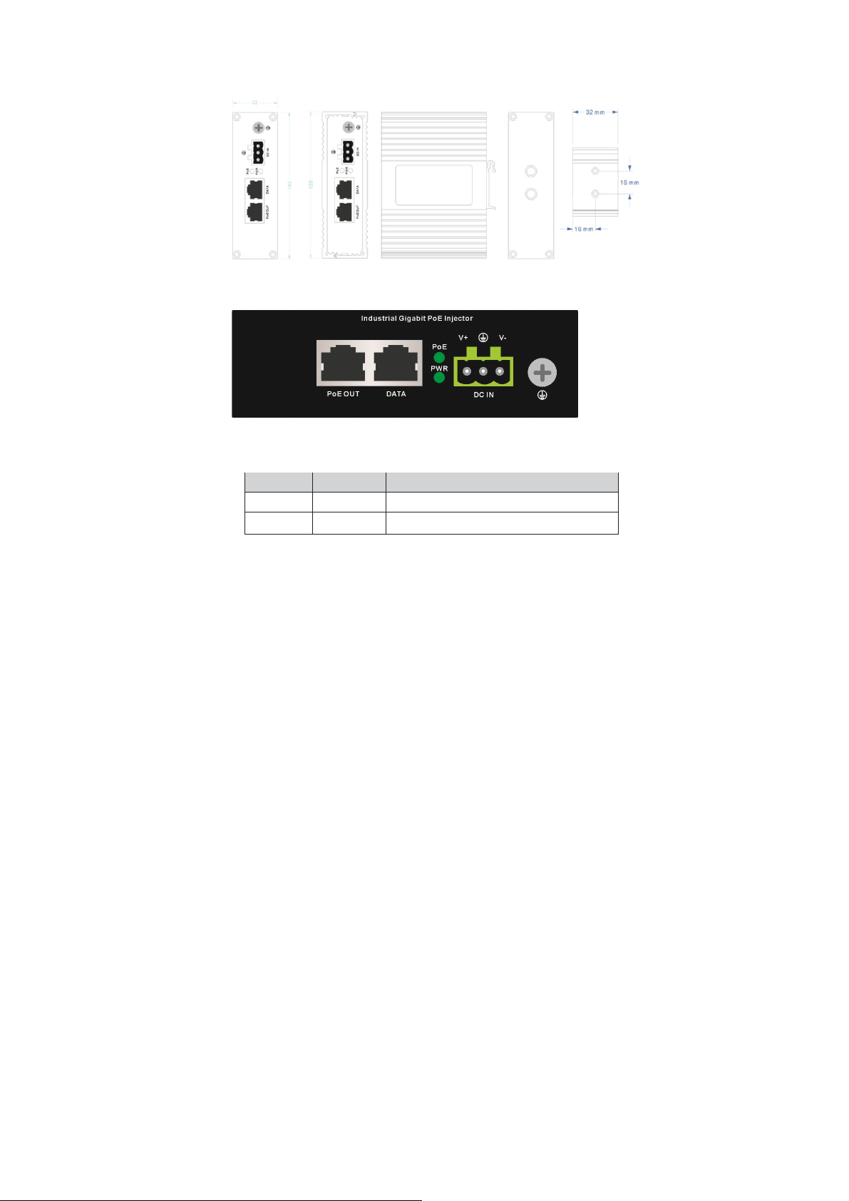
4.1 Physical Dimension
Figure 1
4.2 Product Outlook
LED Indicators
Figure 2
LED Color Function
PWR Green Indicate the device has power.
PoE Green
Indicate the port is providing power
4.3 Wiring the Power Inputs
The 3-contact terminal block connector on the top panel of
Industrial PoE Injector is used for DC power input. Please follow
the steps below to insert the power wire.
Page 7
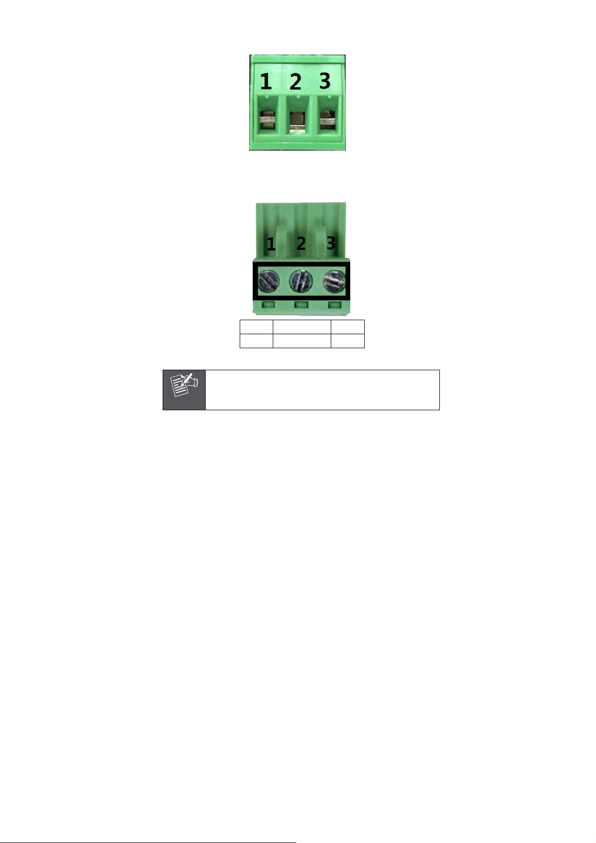
1. Insert Positive/Negative DC power wires into the contacts 1
and 3 for POWER.
Figure 3: Power input PINs.
2. Tighten the wire-clamp screws for preventing the wires from
losing.
1 2 3
V+ Ground V-
Figure 4: Pin of Terminal Block.
The wire gauge for the terminal block should be in the
Note
range between 12 ~ 24
Page 8

5. Mounting Installation
This section describes how to install the Industrial Equipment and
make connections to it. Please read the following topics and
perform the procedures in the order being presented.
In the installation steps below, this Manual use 8 Port
Industrial Gigabit Switch as the example. However, the
Note
5.1 DIN-Rail Mounting
The DIN-Rail is already screwed on the Industrial Equipment. Please
refer to following figures and know how to hang the Industrial
Equipment:
Step 1: Lightly press the button of DIN-Rail into the track.
steps for Industrial slim type Switch, Industrial Media/
Serial Converter and Industrial PoE equipment are
similar.
2
Figure 5: Install Industrial Equipment in DIN-Rail mount.
Page 9

Step 2: Check the DIN-Rail is tightly on the track.
Figure 6: Industrial Equipment installed in DIN-Rail mount.
5.2 Remove DIN-Rail Mounting
Step 1: Please refer to following procedures to remove the
Industrial Equipment from the track.
1
2
Figure 7: Remove Industrial Equipment in DIN-Rail mount.
Step 2: Lightly press the button of DIN-Rail for remove it from the
track.
Page 10

6. Hardware Installation
This Industrial IEEE 802.3at Gigabit High Power over Ethernet
Injector provides three different running speeds – 10Mbps,
100Mbps and 1000Mbps in the same device and automatically
distinguishes the speed of incoming connection. Please refer to
following sections for detail information about Industrial
IEEE 802.3at Gigabit High Power over Ethernet Injector.
Before Installation
Before your installation, it is recommended to check your
network environment. If there has any IEEE 803.3af or
IEEE 802.3at devices need to power on, the PoE Injector can
provide you a way to supply power for this Ethernet device
conveniently and easily.
Installation
1. Connect the Power (Range from DC 45 ~ 56V) to 3-pin terminal
block of PoE Injector. The “PWR” LED will be steady on.
2. Connect a standard network cable from Switch/workstation
to “DATA” port of PoE Injector.
3. Connect the long cable that will be used to connect to the
remote device to the port “PoE OUT”.
4. Due to the capability of IEEE 802.3at Power over Ethernet,
the PoE Injector can directly connect with any IEEE 802.3at/
IEEE 802.3af devices.
5. Once PoE Injector detects the existence of an IEEE 802.3at
device, the “PoE” LED indicator will be steady on.
Page 11

Hereby Assmann Electronic GmbH, declares that the Declaration of Conformity
is part of the shipping content. If the Declaration of Conformity is missing, you
can request it by post under the below mentioned manufacturer address.
www.assmann.com
Assmann Electronic GmbH
Auf dem Schüffel 3
58513 Lüdenscheid
Germany
 Loading...