

Page 1

8 10/100TX + 2 10/100/1000T/100/1000 SFP
Combo with 8 PoE Injectors Industrial Switch
User Manual
DN-650102
Page 2

FCC Warning
This Equipment has been tested and found to comply with the limits for a
Class-A digital device, pursuant to Part 15 of the FCC rules. These limits
are designed to provide reasonable protection against harmful interference
in a residential installation. This equipment generates, uses, and can
radiate radio frequency energy. It may cause harmful interference to radio
communications if the equipment is not installed and used in accordance
with the instructions. However, there is no guarantee that interference will
not occur in a particular installation. If this equipment does cause harmful
interference to radio or television reception, which can be determined by
turning the equipment off and on, the user is encouraged to try to correct
the interference by one or more of the following measures:
Reorient or relocate the receiving antenna.
Increase the separation between the equipment and receiver.
Connect the equipment into an outlet on a circuit different from that to
which the receiver is connected.
Consult the dealer or an experienced radio/TV technician for help.
CE Mark Warning
This is a Class-A product. In a domestic environment this product may
cause radio interference in which case the user may be required to take
adequate measures.
Page 3

Content
Introduction ................................................................ 1
Features ................................................................... 1
Package Contents .................................................... 2
Hardware Description ............................................... 3
Physical Dimension .................................................. 3
Front Panel .............................................................. 3
Top View .................................................................. 4
LED Indicators ......................................................... 5
Ports ......................................................................... 6
Cabling ..................................................................... 8
Wiring the Power Inputs ......................................... 11
Wiring the Fault Alarm Contact .............................. 11
Mounting Installation .............................................. 13
DIN-Rail Mounting .................................................. 13
Wall Mount Plate Mounting .................................... 15
Hardware Installation .............................................. 16
Installation Steps .................................................... 16
Network Application ................................................ 17
Troubles shooting ................................................... 19
Technical Specification ........................................... 20
Page 4

1
Introduction
The 8 10/100TX + 2 10/100/1000T/100/1000 SFP Combo with 8 PoE Injectors Industrial
Switch is a cost-effective solution and meets the high reliability requirements demanded
by industrial applications. Using fiber port can extend the connection distance that
increases the network elasticity and performance.
Features
System Interface/Performance
RJ-45 ports support Auto MDI/MDI-X Function
Embedded 8-port PoE Injection
SFP (Mini-GBIC) supports 100/1000 Dual Mode
Store-and-Forward Switching Architecture
Back-plane (Switching Fabric): 5.6Gbps
1Mbits Packet Buffer
8K MAC Address Table
Supports Wide Operating Temperature (-40oC ~ 75oC)
Power Supply
Redundant Power Design
Case/Installation
IP-30 Protection
DIN Rail and Wall Mount Design
Relay Alarm
Relay output for port breakdown, power fail and alarm
Page 5

2
Package Contents
Please refer to the package contents list below to verify them against the checklist.
8 10/100TX + 2 10/100/1000T/100/1000 SFP Combo with 8 PoE Injectors Industrial
Switch
User manual
Pluggable Terminal Block
2 wall mount plates and 6 screws
One DIN-Rail (attached on the switch)
8 10/100TX + 2 10/100/1000T/100/1000 SFP Combo with 8 PoE Injectors Industrial Switch
User Manual block connector
Wall Mount Plate Screws DIN-Rail
Compare the contents of the industrial switch with the standard checklist above. If any
item is damaged or missing, please contact the local dealer for service.
Page 6

3
Hardware Description
In this paragraph, the Industrial switch’s hardware spec, port, cabling information, and
wiring installation will be described.
Physical Dimension
8 10/100TX + 2 10/100/1000T/100/1000 SFP Combo with 8 PoE Injectors Industrial
Switch dimension (W x D x H) is 72mm x 105mm x 152mm
Front Panel
The Front Panel of the 8 10/100TX + 2 10/100/1000T/100/1000 SFP Combo with 8 PoE
Injectors Industrial Switch is shown as below:
Front Panel of the PoE Injectors Industrial Switch
Page 7

4
Top View
The top view of the 8 10/100TX + 2 10/100/1000T/100/1000 SFP Combo with 8 PoE
Injectors Industrial Switch has one terminal block connector of two DC power inputs.
Top View of the PoE Injectors Industrial Switch
Page 8

5
LED Indicators
The diagnostic LEDs located on the front panel of the industrial switch provide real-time
information of system and optional status. The following table provides the description of
the LED status and their meanings for the switch.
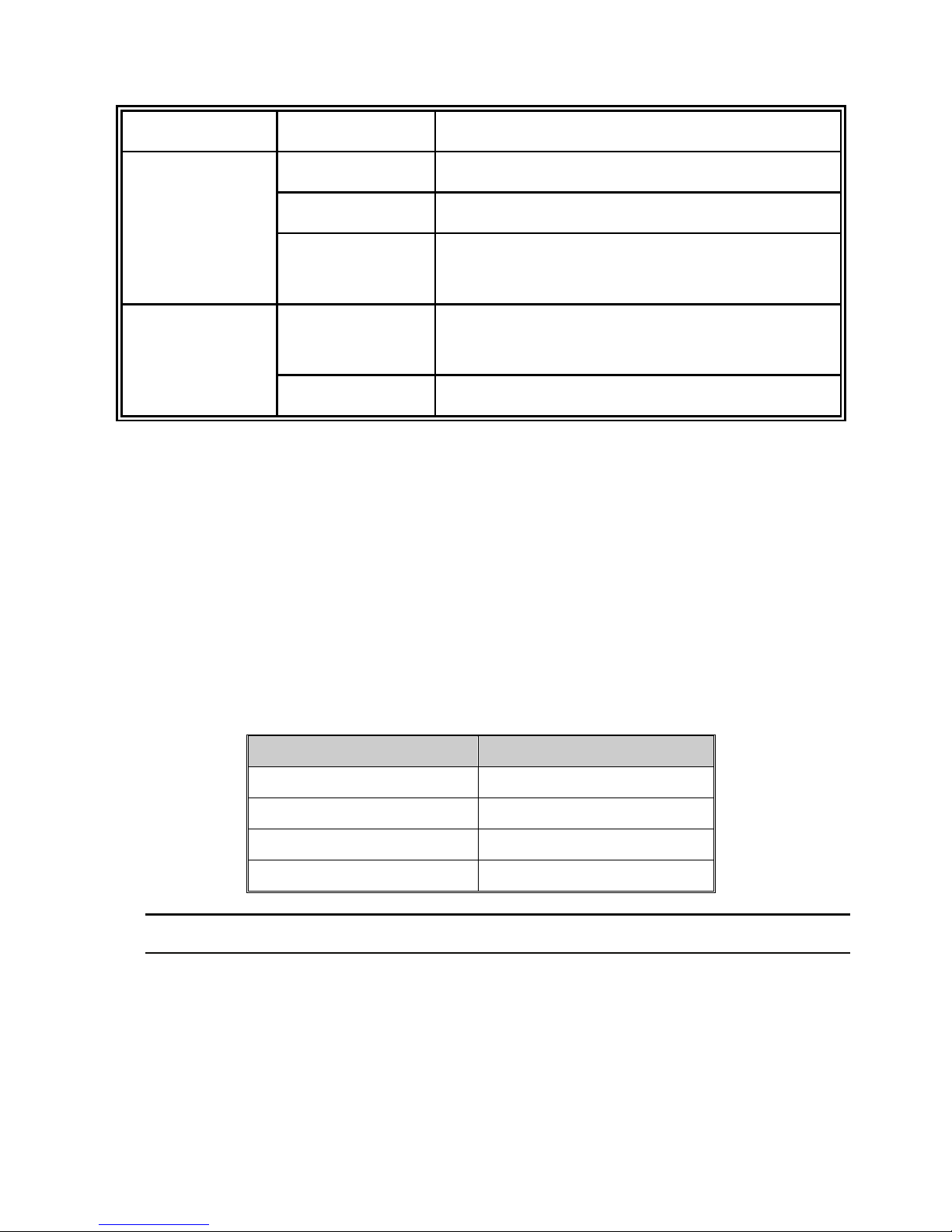
LED Status Meaning
PWR1
Green Power 1 is active
OFF No power inputs
PWR2
Green Power 2 is active
OFF No power inputs
Fault
Red Power input 1 or 2 is inactive
OFF
Power 1 & Power 2 are both active or no power
inputs
P9, P10 (RJ-45)
Upper
LED
Green Connected to network
Blinking Networking is active
OFF Not connected to network
Lower
LED
Green The port is operating at speed of 1000M
OFF
The port is disconnected or not operating at
speed of 1000M
Link/Active
(P9, P10)
Green SFP port is linking
Blinks Data is transmitting or receiving
OFF Not connected to network
P1 ~ P8
(Green)
Green Connected to network
Blinking
Networking is active
Page 9
6
OFF Not connected to network
P1 ~ P8
(Yellow)
Yellow Ethernet port full duplex
Blinking Collision of packet occurs
OFF
Ethernet port half duplex or not connected to
network
FWD (P1 ~ P8)
Green
A powered device is connected utilizing Power
over Ethernet on the port
OFF No device is connected or power forwarding fails
Ports
RJ-45 ports
The UTP (RJ-45) Fast Ethernet ports will auto-sense for 10Base-T or 100Base-TX
connections. Auto MDI/MDIX means that the switch can connect to another switch or
workstation without changing straight through or crossover cabling. See the below
figures for straight through and crossover cable schematic.
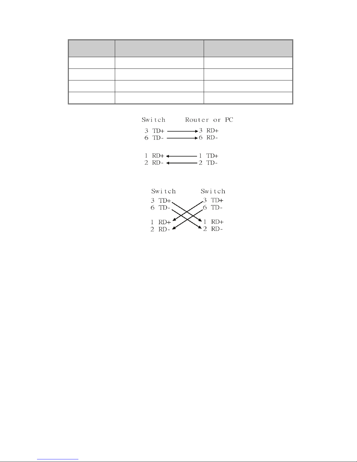
RJ-45 Pin Assignments
Pin Number Assignment
1 Tx+
2 Tx-
3 Rx+
6 Rx-
[NOTE] “+” and “-” signs represent the polarity of the wires that make up each wire pair.
All ports on this industrial switch support automatic MDI/MDI-X operation, user can use
straight-through cables (See figure below) for all network connections to PCs or servers,
or to other switches or hubs. In straight-through cable, pins 1, 2, 3, and 6, at one end of
the cable, are connected straight through to pins 1, 2, 3 and 6 at the other end of the
cable. The table below shows the 10BASE-T/100BASE-TX MDI and MDI-X port pin outs.
Page 10
7
Pin MDI-X Signal Name MDI Signal Name
1 Receive Data plus (RD+) Transmit Data plus (TD+)
2 Receive Data minus (RD-) Transmit Data minus (TD-)
3 Transmit Data plus (TD+) Receive Data plus (RD+)
6 Transmit Data minus (TD-) Receive Data minus (RD-)
Straight Through Cable Schematic
Cross Over Cable Schematic
2 Mini-GBIC combo port: 2 auto-detect Giga port—UTP or fiber. The gigabit
Ethernet ports are shared with the mini-GBIC ports. UTP (Gigabit Ethernet) ports
can operate in half/full-duplex modes and work at speeds of 10/100/1000Mbps that
support auto-sensing technology to enable each port to detect the connecting speed.
The mini-GBIC port is a joint for a mini-GBIC (SFP) transceiver, so the switch can
be uplinked through fiber to another one.
Page 11
8
Cabling
Use four twisted-pair, Category 5e or above cabling for RJ-45 port connection. The
cable between the switch and the link partner (switch, hub, workstation, etc.) must
be less than 100 meters (328 ft.) long.
Use the mini-GBIC ports to uplink to another switch by inserting the mini-GBIC (SFP)
transceiver.
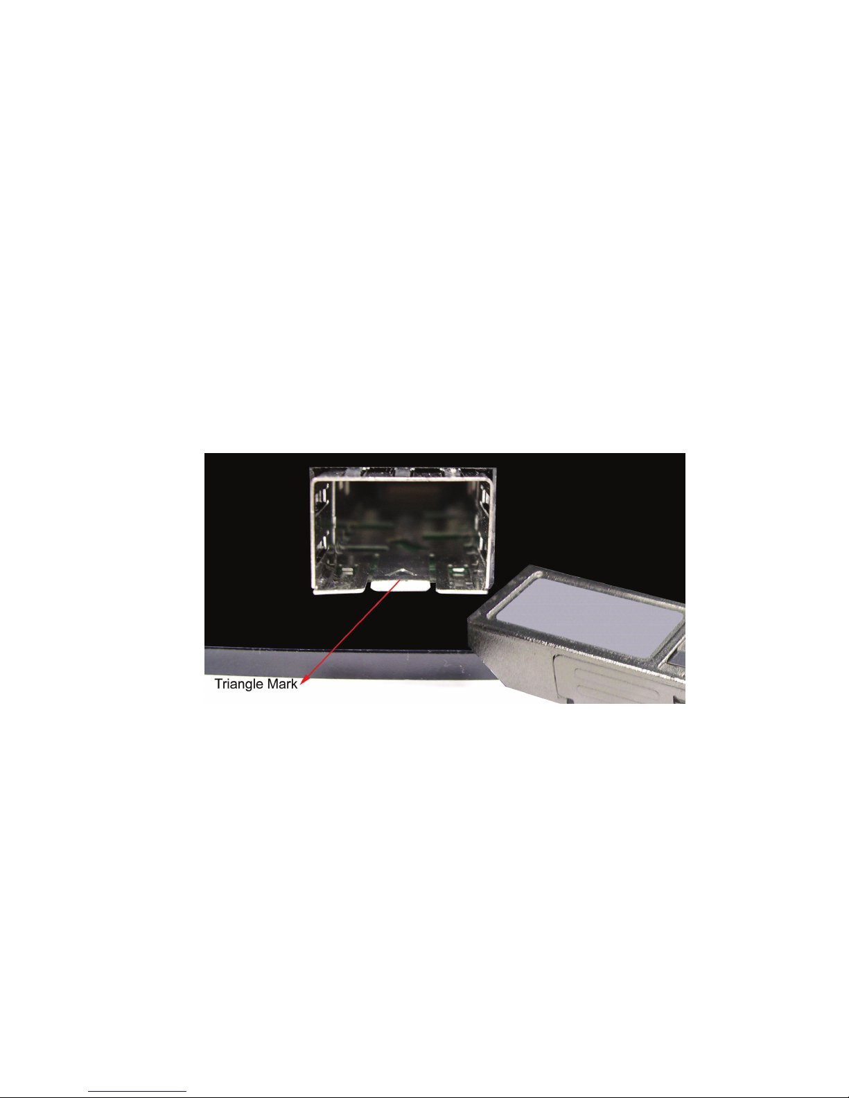
To connect the transceiver and LC cable, please follow the steps shown below:
First, insert the transceiver into the SFP module. Notice that the triangle mark is the
bottom of the module.
Figure 2.8: Transceiver to the SFP module
Page 12
9
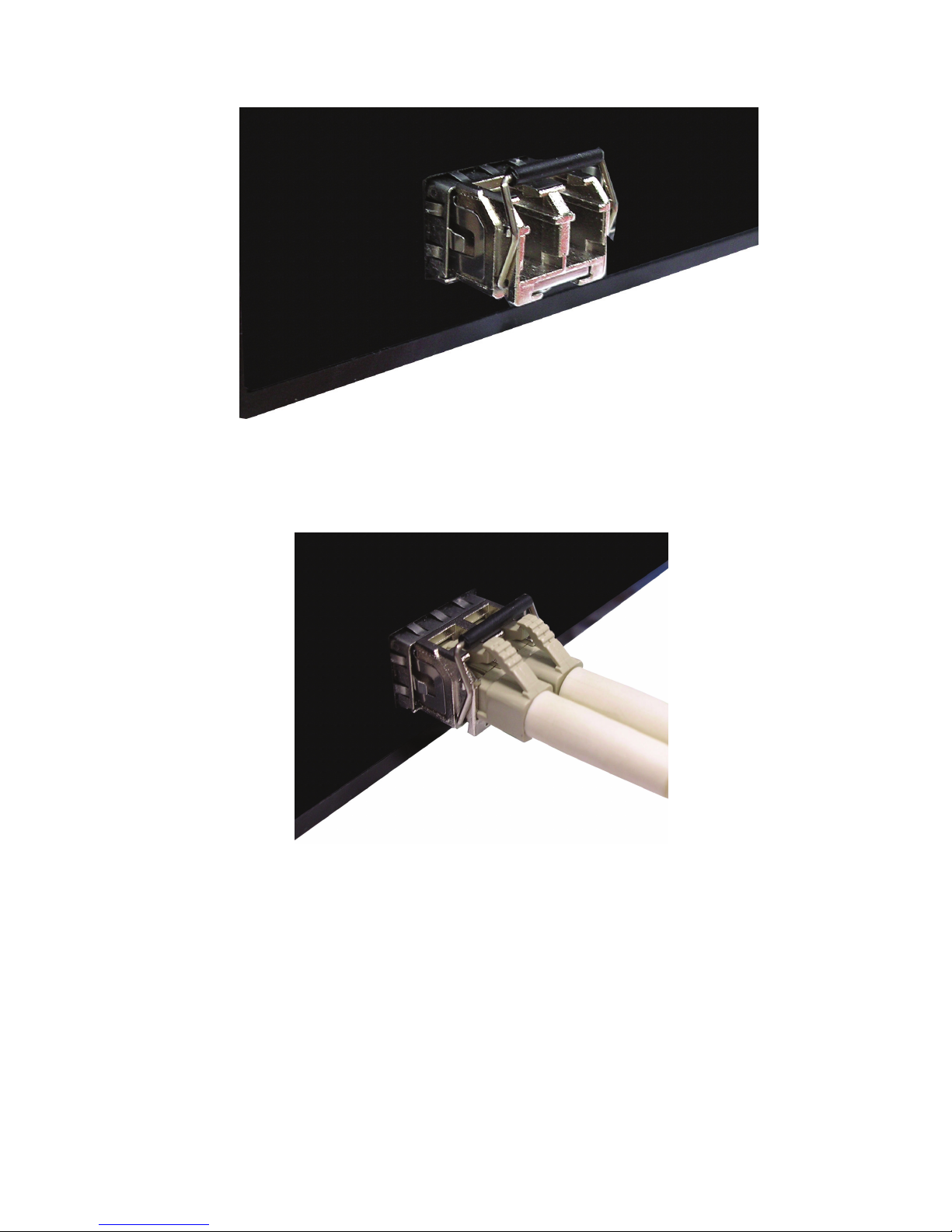
Figure 2.9: Transceiver Inserted
Second, insert the fiber cable of LC connector into the transceiver.
Figure 2.10: LC connector to the transceiver
Page 13
10
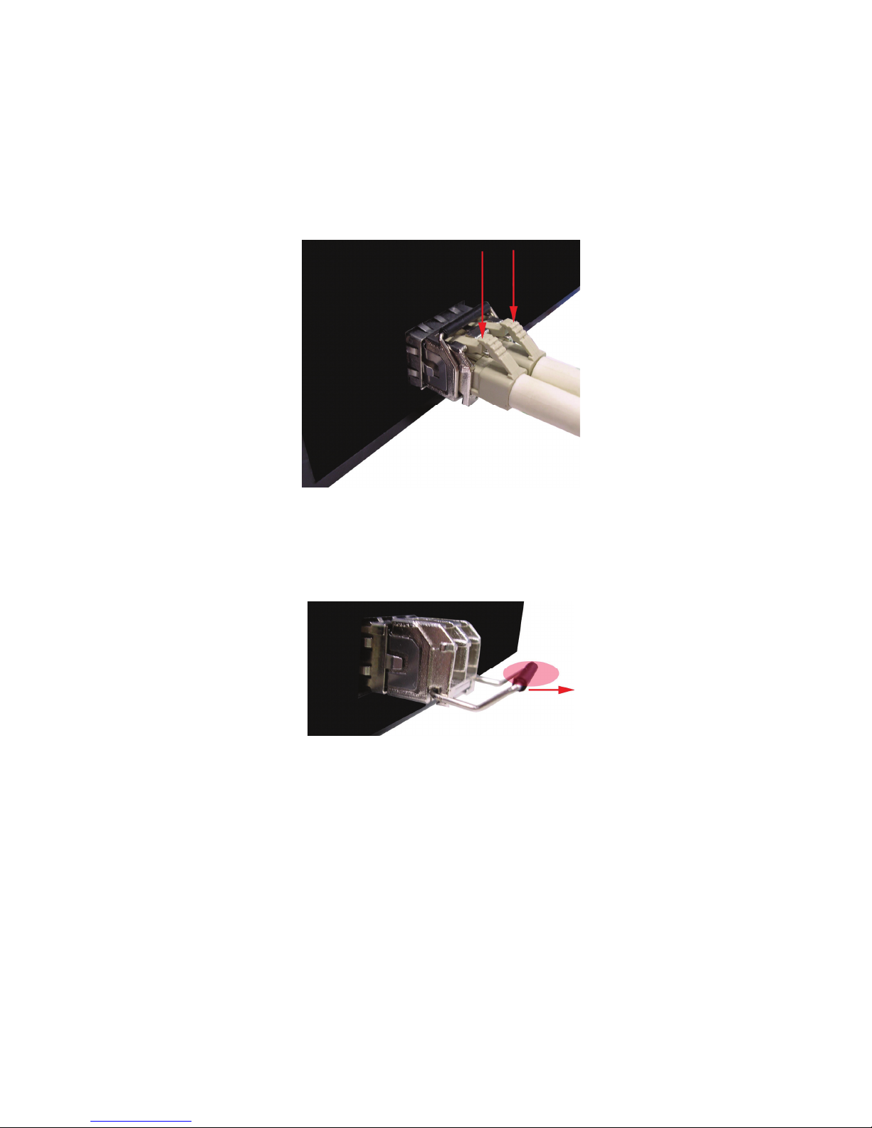
To remove the LC connector from the transceiver, please follow the steps shown below:
First, press the upper side of the LC connector to release from the transceiver and pull it
out.
Figure 2.11: Remove LC connector
Second, push down the metal loop and pull the transceiver out by the plastic handle.
Figure 2.12: Pull out from the transceiver
Page 14
11
Wiring the Power Inputs
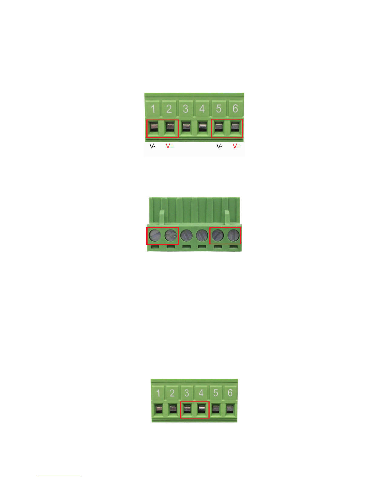
Please follow the steps below to insert the power wire.
Insert the positive and negative wires into the V+ and V- contacts on the terminal block
connector.
Tighten the wire-clamp screws for preventing the wires from loosing.
Wiring the Fault Alarm Contact
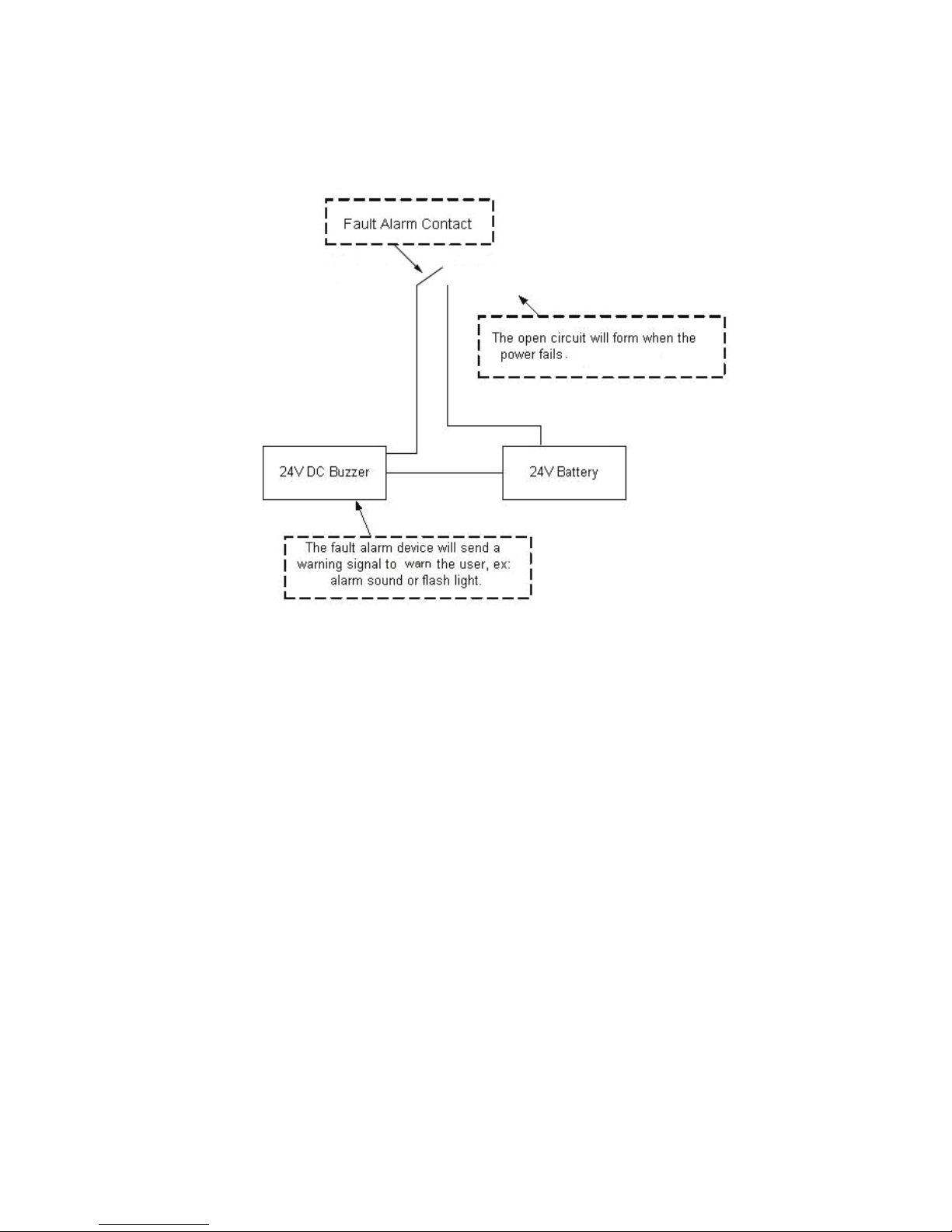
The fault alarm contact is in the middle of terminal block connector as the picture shows
below. Inserting the wires, it will detect the fault status including power failure or port link
failure (managed industrial switch only) and form an open circuit. An application example
for the fault alarm contact is shown as below:
Insert the wires into the fault alarm contact.
Page 15
12
Note
The wire gauge for the terminal block should be in the range
between 12~ 24 AWG.
Page 16
13
Mounting Installation
DIN-Rail Mounting
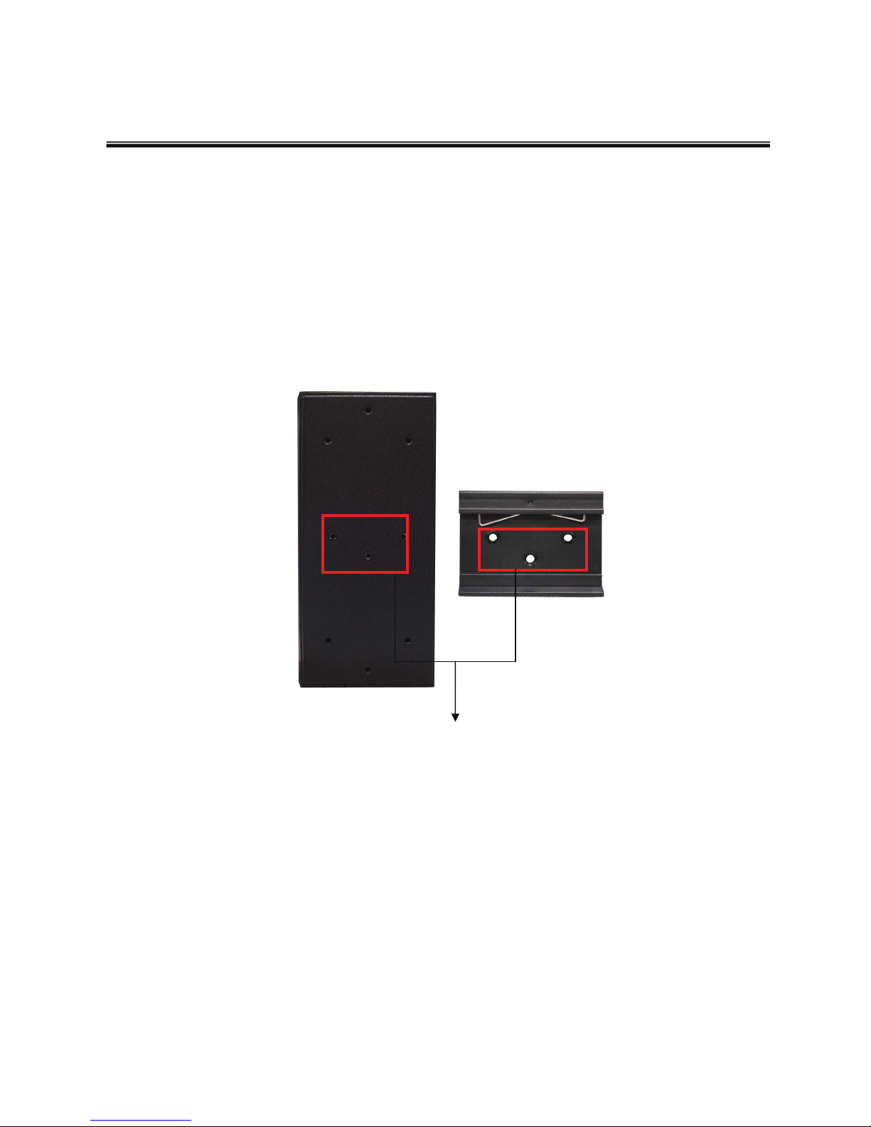
The DIN-Rail is screwed on the industrial switch when out of factory. If the DIN-Rail is
not screwed on the industrial switch, please see the following pictures to screw the DIN-
Rail on the switch. Follow the steps below to hang the industrial switch.
1. Use the screws to screw the DIN-Rail on the industrial
switch
2. To remove the DIN-Rail, reverse the step 1.
Rear Panel of the switch
DIN-Rail
Page 17
14
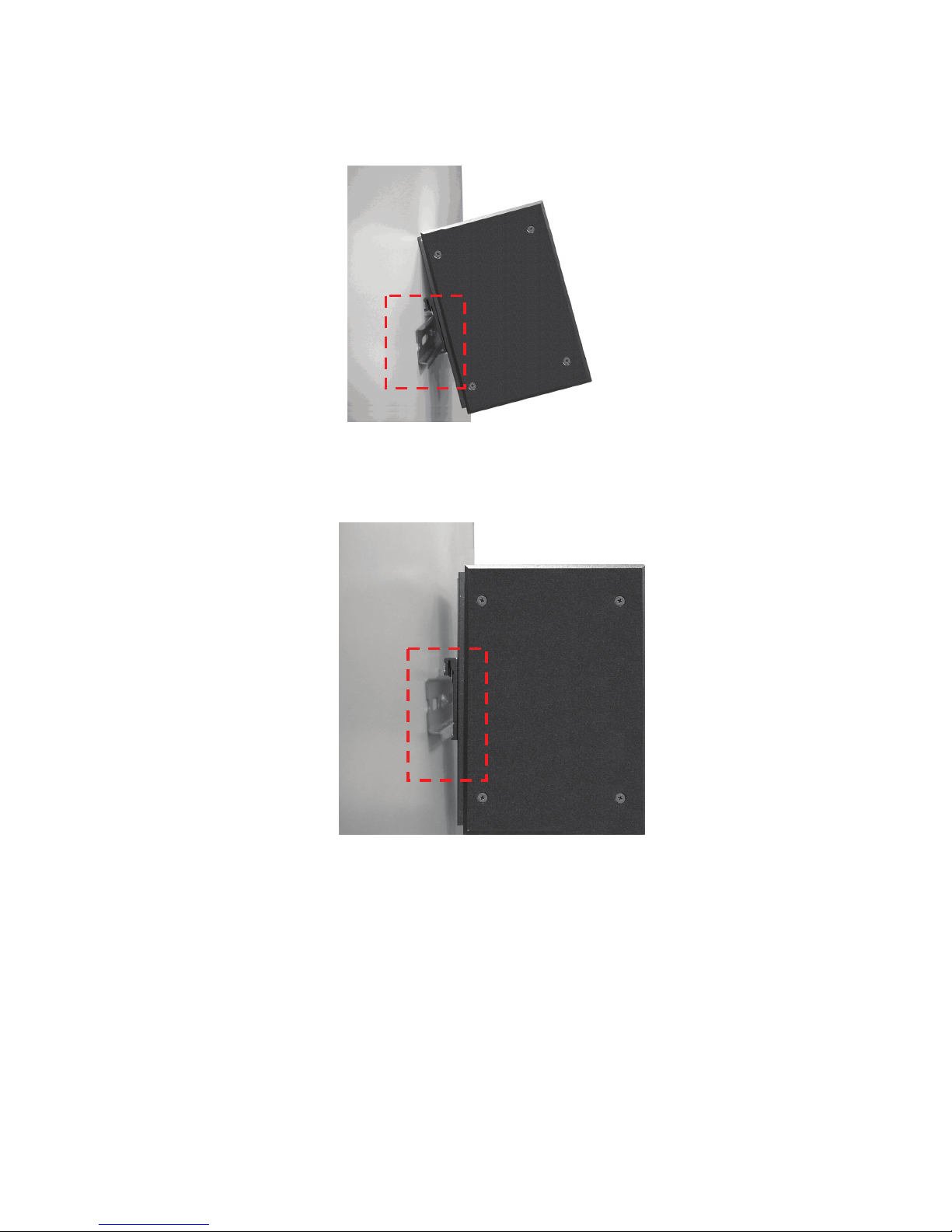
1. First, insert the top of DIN-Rail into the track.
2. Then, lightly push the DIN-Rail into the track.
3. Check if the DIN-Rail is tightened on the track or not.
4. To remove the industrial switch from the track, reverse steps above.
Page 18
15
Wall Mount Plate Mounting
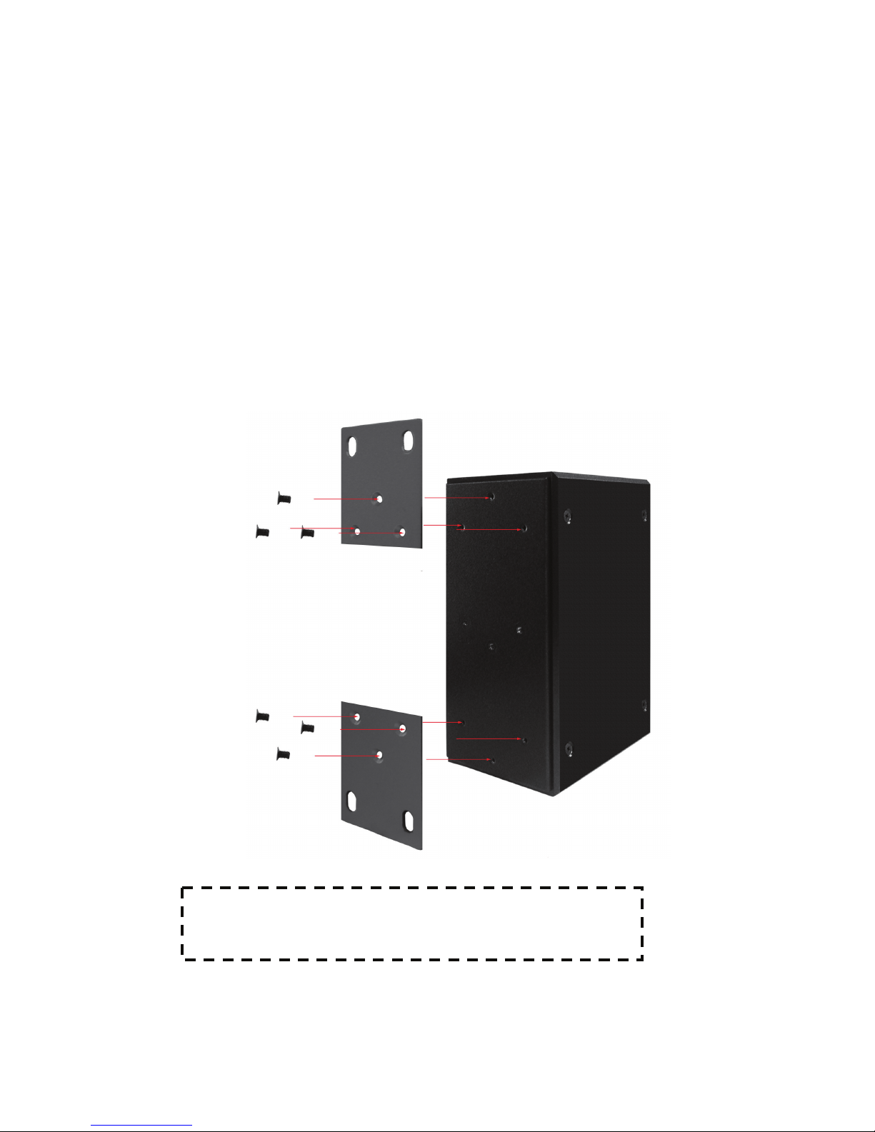
Follow the steps below to mount the industrial switch with wall mount plate.
1. Remove the DIN-Rail from the industrial switch; loose the screws to remove the DIN-
Rail.
2. Place the wall mount plate on the rear panel of the industrial switch.
3. Use the screws to screw the wall mount plate on the industrial switch.
4. Use the hook holes at the corners of the wall mount plate to hang the industrial
switch on the wall.
5. To remove the wall mount plate, reverse steps above.
Screw the wall mount plate on the Industrial Switch
Page 19

16
Hardware Installation
In this paragraph, we are going to mention how to install the 8 10/100TX + 2
10/100/1000T/100/1000 SFP Combo with 8 PoE Injectors Industrial Switch and the
installation points to be attended to it.
Installation Steps
1. Unpack the Industrial switch packing.
2. Check if the DIN-Rail is screwed on the Industrial switch or not. If the DIN-Rail is not
screwed on the Industrial switch, please refer to DIN-Rail Mounting section for DIN-
Rail installation. If user want to wall mount the Industrial switch, then please refer to
Wall Mount Plate Mounting section for wall mount plate installation.
3. To hang the Industrial switch on the DIN-Rail track or wall, please refer to the
Mounting Installation section.
4. Power on the Industrial switch. Please refer to the Wiring the Power Inputs section
for knowing the information about how to wire the power. The power LED on the
Industrial switch will light up. Please refer to the LED Indicators section for indication
of LED lights.
5. Prepare the twisted-pair, straight through Category 5e/above cable for Ethernet
connection.
6. Insert one side of the RJ-45 cable into the Industrial switch Ethernet port and another
side to the network device’s Ethernet port, e.g. Switch, PC or Server. The UTP port
(RJ-45) LED on the Industrial switch will light up when the cable is connected with
the network device. Please refer to the LED Indicators section for LED light
indication.
7. When all connections are set and LED lights all show in normal, the installation is
complete.
Page 20
17
Network Application
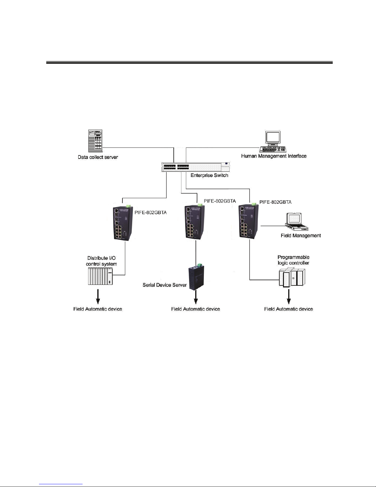
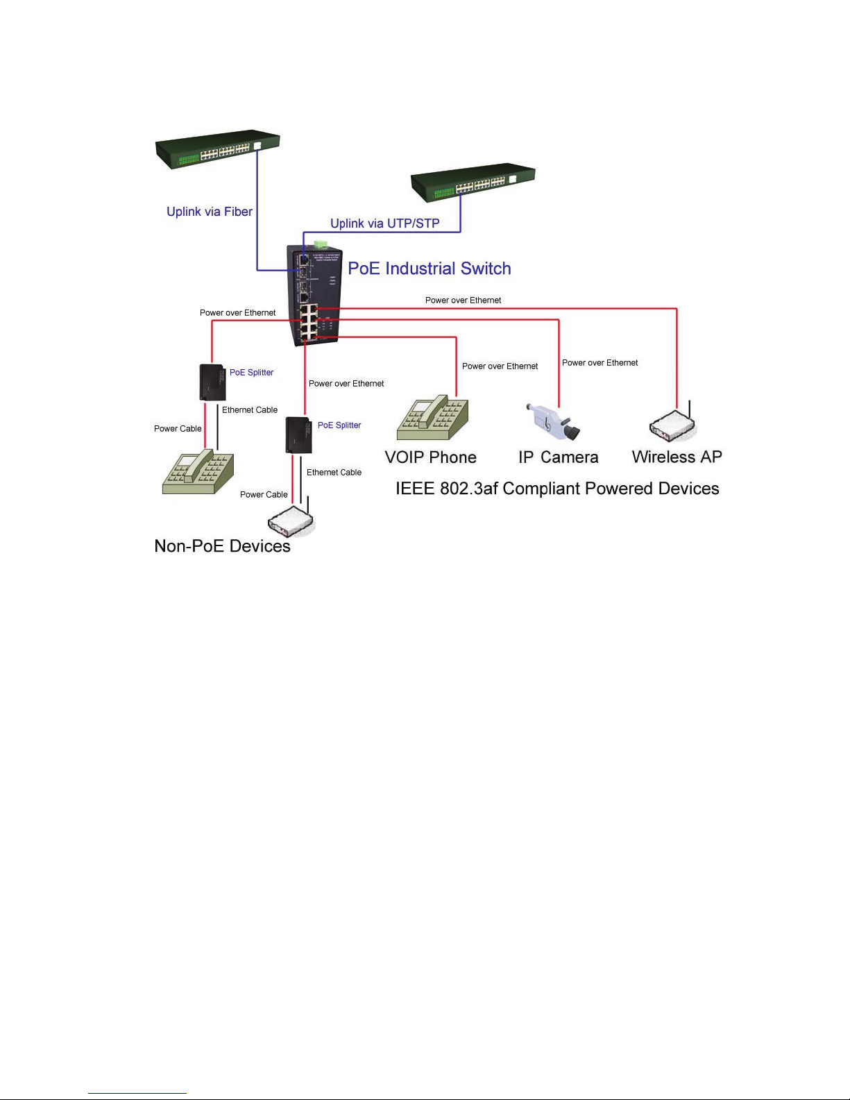
This segment provides the samples to help user have more actual idea of industrial
switch application. For a sample application of the industrial switch, see the figures
below.
Page 21
18
Page 22

19
Troubles shooting
Verify that is using the right power cord/adapter (DC 48V), please don’t use the
power adapter with DC output voltage higher than 48V, or it will burn this converter
down.
Select the proper UTP cable to construct user network. Please check that is using
the right cable. Use unshielded twisted-pair (UTP) or shielded twisted-pair (STP)
cable for RJ-45 connections: 100Ω Category 3, 4 or 5 cable for 10Mbps connections,
100Ω Category 5 cable for 100Mbps connections or 100Ω Category 5e/above cable
for 1000Mbps. Also be sure that the length of any twisted-pair connection does not
exceed 100 meters (328 feet).
Diagnosing LED Indicators: the Switch can be easily monitored through panel
indicators, which describes common problems user may encounter and where user
can find possible solutions, to assist in identifying problems.
If the power indicator does not light on when the power cord is plugged in, user may
have a problem with power cord. Then check for loose power connections, power
losses or surges at power outlet. If you still cannot resolve the problem, contact the
local dealer for assistance.
If the Industrial switch LED indicators are normal and the connected cables are
correct but the packets still cannot transmit. Please check your system’s Ethernet
devices’ configuration or status.
Page 23
20
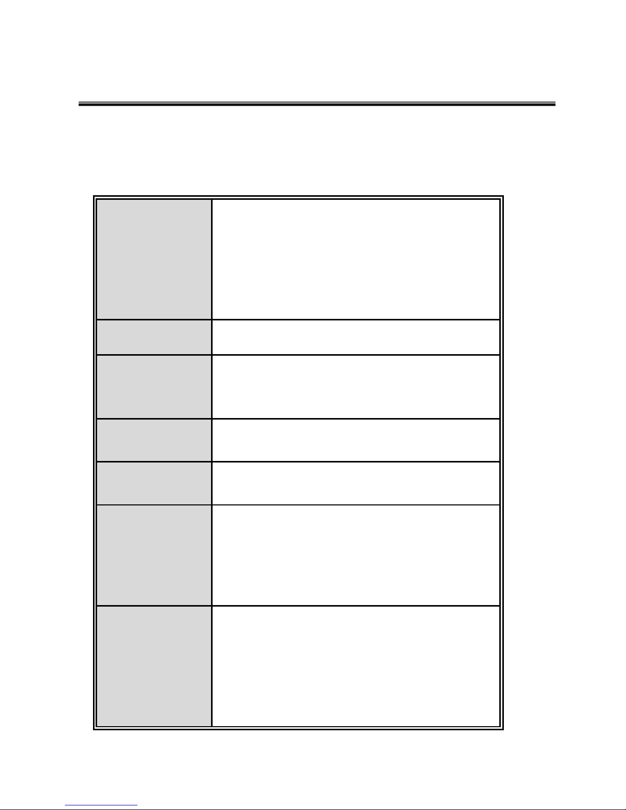
Technical Specification
8 10/100TX + 2 10/100/1000T/100/1000 SFP Combo with 8 PoE Injectors Industrial
Switch technical specifications is shown as below.
Standard
IEEE 802.3 10Base-T Ethernet
IEEE 802.3u 100Base-TX/FX
IEEE802.3ab 1000Base-T
IEEE802.3z Gigabit fiber
IEEE802.3x Flow Control and Back Pressure
IEEE802.3af Power over Ethernet
Protocol
CSMA/CD
Transfer Rate
14,880 pps for 10Base-T Ethernet port
148,800 pps for 100Base-TX/FX Fast Ethernet port
1,488,000 pps for Gigabit Fiber Ethernet port
Packet Buffer
1Mbits
MAC address
8K MAC address table
LED
8 ports 10/100TX : Link/Activity (Green), Full
duplex/Collision (Yellow), Power Feeding (Green)
Giga port: Link/Activity (Green)
Per unit: Power 1 (Green), Power 2 (Green), Fault
(Red)
Network Cable
10Base-T: 2-pair UTP/STP Cat. 3, 4, 5, 5e cable
EIA/TIA-568 100-ohm (100m)
100Base-TX: 2-pair UTP/STP Cat. 5/5E cable
EIA/TIA-568 100-ohm (100m)
1000Base-TX: 2-pair UTP/STP Cat. 5E cable
EIA/TIA-568 100-ohm (100m)
Page 24
21
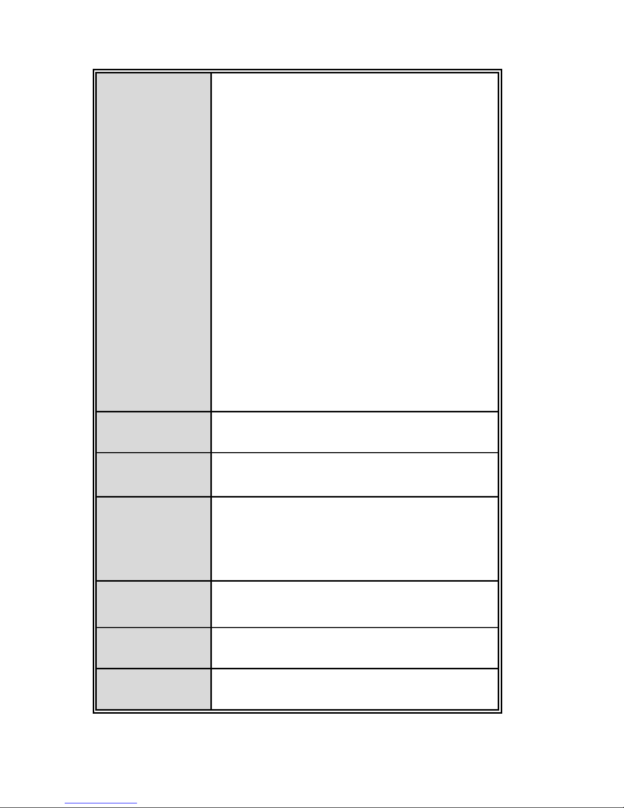
Optical cable
Distance:
Multi mode:
0 to 5 km, 1300 nm (50/125 μm, 800 MHz*km)
0 to 4 km, 1300 nm (62.5/125 μm, 500 MHz*km)
Single mode:
0 to 40 km, 1310 nm (9/125 μm, 3.5 PS/(nm*km))
0 to 80 km, 1550 nm (9/125 μm, 19 PS/(nm*km))
Min. TX Output:
Multi mode: -20 dBm
Single mode: 0 to 40 km, -5 dBm; 0 to 80 km, -5
dBm
Max. TX Output:
Multi mode: -14 dBm
Single mode: 0 to 40 km, 0 dBm; 0 to 80 km, 0 dBm
Sensitivity:
-36 to -32 dBm (Single mode); -34 to -30 dBm (Multi
mode)
Back-plane
(Switching Fabric)
5.6Gbps
Packet throughput
ability
8.3Mpps at 64bytes
Power Supply
External Power Supply: DC 48V
Redundant power DC 48V with connective
removable terminal block
Power
Consumption
140 Watts (maximum)
Install
DIN rail kit and wall-mount ear for DIN-type cabinet
install and wall mounting
Operating
Temperature
-40
o
C ~ 75oC (Wide Operating Temperature model)
-10
o
C ~ 60oC (standard model)
Page 25
22
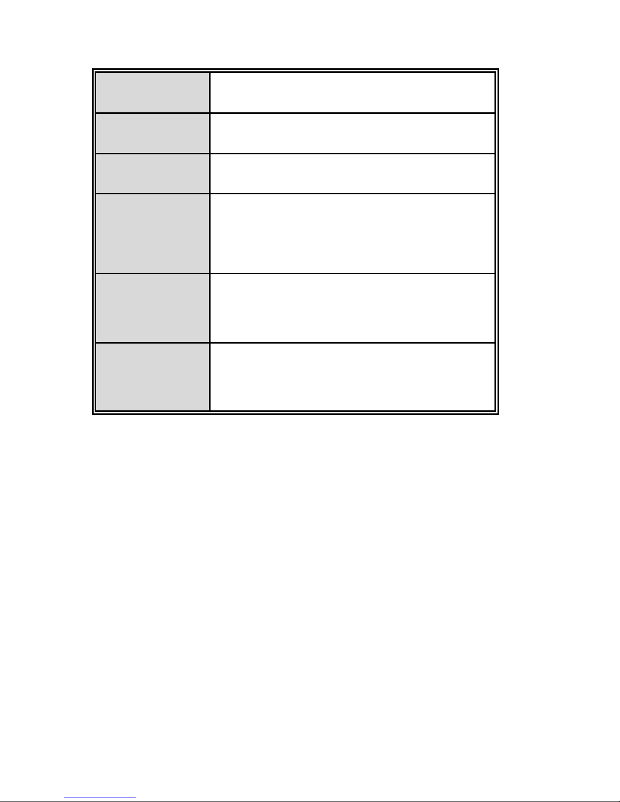
Operating
Humidity
5% to 95% (Non-condensing)
Storage
Temperature
-40oC to 85oC
Case Dimension
IP-30, 72 mm (W) x 105 mm (D) x 152mm (H)
EMI
FCC Class A
CE EN61000-4-2/3/4/5/6/8/11/12
CE EN61000-6-2
CE EN61000-6-4
Safety
UL
cUL
CE/EN60950-1
Stability testing
IEC60068-2-32 (Free fall)
IEC60068-2-27 (Shock)
IEC60068-2-6 (Vibration)
www.assmann.com
ASSMANN Electronic GmbH
Auf dem Schüffel 3
58513 Lüdenscheid
Germany
 Loading...