

Page 1
Full HD Hybrid AHD and IP
Network Video Recorder
Manual
DN-16121
1
Page 2

Contents
SAFETY INSTRUCTION ..................................................................................... 3
Chapter 1
1.1
1.2
Rear Panel ............................................................................................. 1
Remote Controller (For Reference Only) ............................................... 2
Chapter 2
2.1
2.2
2.3
HDD Installation ..................................................................................... 3
Connection Diagram .............................................................................. 4
Power Supply Connection ...................................................................... 4
Chapter 3
3.1
3.2
3.3
Using the Supplied Mouse ..................................................................... 5
Using the Virtual Keyboard .................................................................... 5
Password & Locking the Screen Operation ........................................... 5
Chapter 4
4.1
4.2
Startup Wizard ....................................................................................... 6
Live Viewing Screen .............................................................................. 9
Chapter 5
Product Overview ........................................................................ 1
DVR Installation & Connection ................................................... 3
DVR Common Operations .......................................................... 5
DVR Starting up ........................................................................... 6
DVR Menu .................................................................................. 12
5.1
5.2
5.3
5.4
5.5
Overview .............................................................................................. 12
Display ................................................................................................. 13
5.2.1
5.2.2
5.2.3
5.2.4
5.2.5
5.2.6
Record ................................................................................................. 20
5.3.1
5.3.2
5.3.3
5.3.4
5.3.5
Capture ................................................................................................ 25
Network ................................................................................................ 27
5.5.1
5.5.2
5.5.3
5.5.4
5.5.5
5.5.6
Analog Channels ......................................................................... 13
IP Channels ................................................................................. 14
Live .............................................................................................. 16
Output ......................................................................................... 17
Image Control .............................................................................. 18
Private Zone ................................................................................ 19
Record ......................................................................................... 20
Record Schedule ......................................................................... 21
Mainstream ................................................................................. 22
Substream ................................................................................... 23
Mobile stream .............................................................................. 24
Network ....................................................................................... 27
E-mail .......................................................................................... 29
E-mail Schedule .......................................................................... 30
DDNS .......................................................................................... 30
RTSP ........................................................................................... 31
FTP ............................................................................................. 32
1
Page 3

5.6
5.6.1
5.6.2
5.6.3
5.7
5.7.1
5.7.2
5.7.3
5.7.4
5.7.5
5.8
5.8.1
5.8.2
5.8.3
5.8.4
5.9
5.9.1
5.9.2
5.9.3
5.9.4
5.9.5
5.9.6
5.10
5.10.1
5.10.2
5.11
Alarm ................................................................................................... 33
Motion ......................................................................................... 33
Alarm ........................................................................................... 34
PTZ Linkage ................................................................................ 36
Record Search & Backup ..................................................................... 37
General ....................................................................................... 37
Events ......................................................................................... 38
Picture ......................................................................................... 39
Playback Video Recordings ......................................................... 41
Play Backup Files ........................................................................ 45
Device .................................................................................................. 48
HDD ............................................................................................ 48
S.M.A.R.T .................................................................................... 49
PTZ Setup & Control ................................................................... 50
Cloud Storage ............................................................................. 52
System ................................................................................................. 54
General ....................................................................................... 54
DST ............................................................................................. 55
NTP ............................................................................................. 55
Users ........................................................................................... 56
Info .............................................................................................. 57
Log .............................................................................................. 58
Advanced .......................................................................................... 59
Maintain ....................................................................................... 59
Events ......................................................................................... 60
Shutdown .......................................................................................... 61
Chapter 6
6.1
6.2
Web Plugin Download and Installation ................................................. 62
Web Client Manager ............................................................................ 65
6.2.1
6.2.2
6.2.3
6.2.4
Chapter 7
7.1
7.2
7.3
Troubleshooting ................................................................................... 72
Usage Maintenance ............................................................................. 73
Accessories (For reference only) ......................................................... 74
Remote Access via Web Client ................................................ 62
Live Interface ............................................................................... 65
Playback ...................................................................................... 67
Remote Setting ............................................................................ 71
Local Setting................................................................................ 71
Appendix .................................................................................... 72
2
Page 4

SAFETY INSTRUCTION
Please carefully read the following safety instruction so as to avoid personal injuries and
prevent the equipment and other connection devices from being damaged.
1. Power sources (note: please use the power supply attached or specified by the
manufacturer)
Never operate the equipment by using unspecified power supply.
2. Never push objects of any kind through openings of DVR
Never push objects of any kind through openings of DVR so as to avoid electric shock or
other accidents.
3. Do not put the equipment in the dusty field
Do not put the equipment in the dusty field.
4. Do not place the equipment under rain or humid environment
Do not place the equipment under humid environment like basement. If the equipment is
accidentally in contact with water, please unplug the power cable and immediately
contact your local dealer.
5. Keep the surface of the equipment clean and dry
Use soft damp cloth to clean the outer case of DVR (do not use liquid aerosol cleaners)
6. Do not operate if any problems are found
If there are any strange smell or sound from DVR, unplug the power cable and contact
the authorized dealer or service center.
7. Do not try to remove the upper cover
Warning: Do not remove the cap of DVR so as to avoid electric shock.
8. Handle with care
If DVR does not work normally because of hitting on the hard object, please contact the
authorized dealer for repair or replacement.
9. Use standard lithium battery (Note: Use the batteries attached or specified by the
manufacturer)
After cutting off the power supply, if the system clock cannot continue to work, please
replace the standard 3V lithium battery on the main board.
Warning: Turn off DVR before replacing the batteries, or you may be suffered from
serious electric shock. Please properly dispose of the used batteries.
10. Put the equipment in a place with good ventilation
The DVR system includes HDD, which produces large amount of heat during operation.
As a result, do not block the ventilation openings (on the top, bottom, both sides and the
reverse side) for cooling the system during operation. Install or put the equipment in the
place with good ventilation.
11. The attached power adapter can only be used for 1 set of DVR. Do not connect
more equipment, or DVR may be restarted repeatedly because of insufficient
power.
12. Prevent the equipment from water dropping or splashing. Do not place objects
containing water, such as flower vase, on the equipment.
3
Page 5
Chapter 1
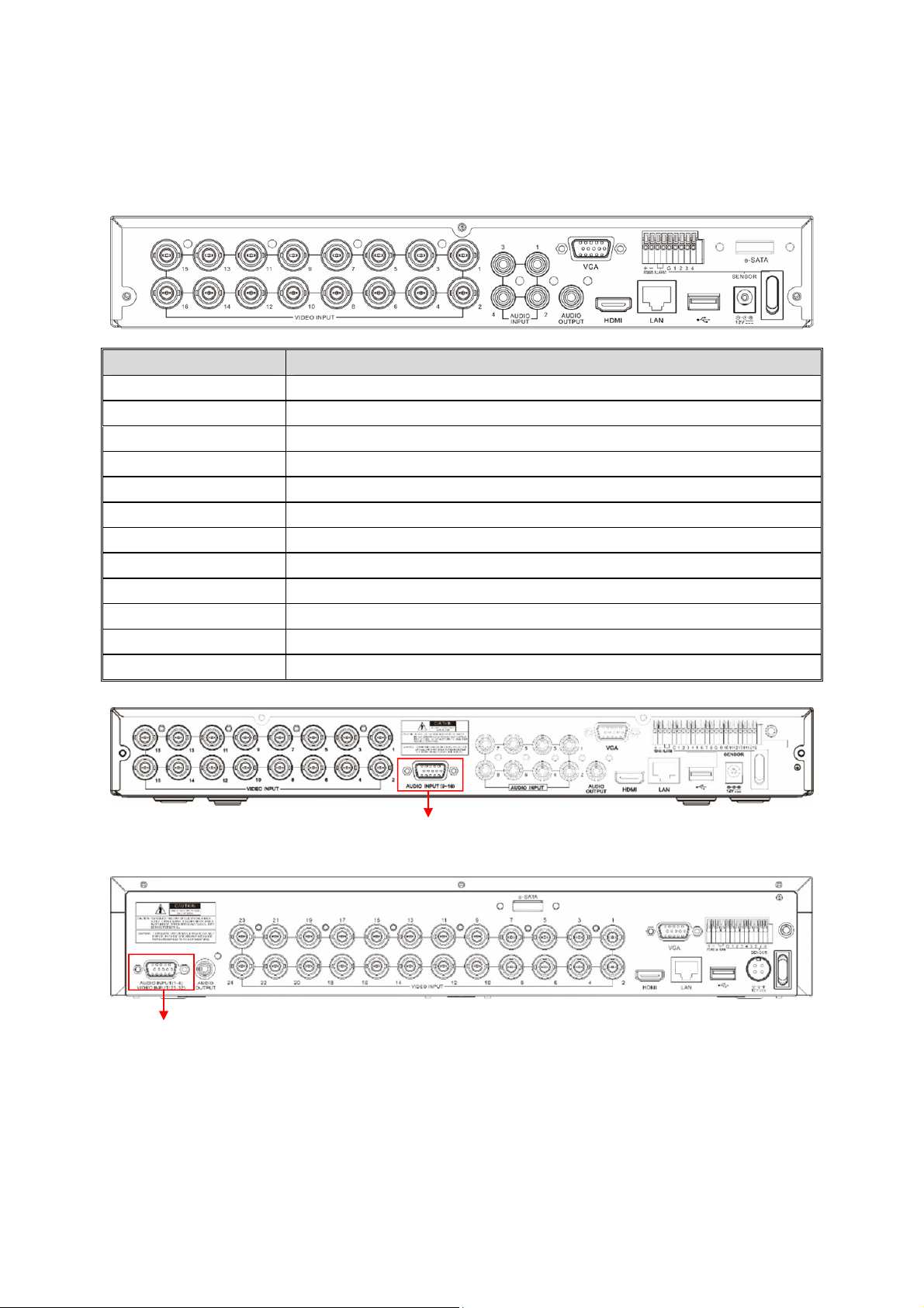
Rear Panel
1.1
Item Description
VIDEO INPUT Connect with video input devices, standard BNC port
AUDIO INPUT Connect with audio input signals, RCA port
AUDIO OUTPUT Audio signal output, RCA port
USB port Connect the supplied mouse or USB flash memory
VGA Connect to your TV or a monitor with VGA input.
HDMI Connect to your digital TV or monitor with HDMI input
LAN Connect to your home network
e-SATA Optional. Connect to e-SATA HDD for recording & backup
RS-485 Connect to PTZ devices
Sensor & Alarm Optional. Connect to external sensor & alarm devices
Power Connect to the supplied power adaptor
Power Switch Turn on/off power supply
Product Overview
AUDIO INPUT (9-16)
For some models to connect to audio inputs with supplied connector
AUDIO INPUT (1-4) & VIDEO INPUT (25-32)
For some 32CH DVR to connect to audio inputs & video inputs (25CH ~ 32CH) with supplied connector
1
Page 6
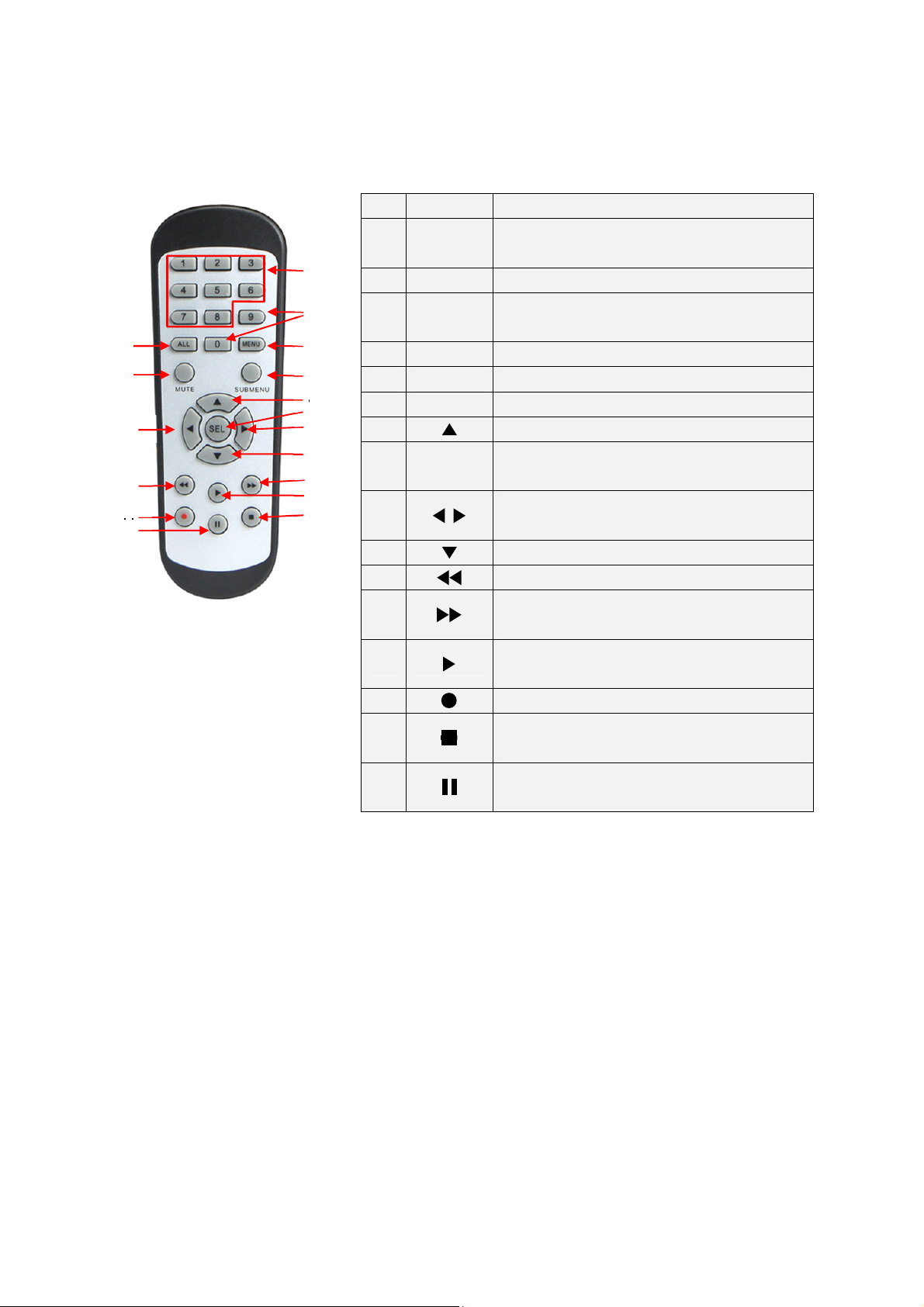
Remote Controller (For Reference Only)
1.2
No. Icon Description
Numeric keys
Press to display channel 1~8
Press to display all channels
Multiple display mode
Press to enter the selected menu item and
edit the setting
Left/Right key; Decrease/increase
parameter value of control bar.
3
5
11
14
16
1 1-8
1
2
4
6
7
8
9
9
10
12
13
15
2 9, 0 Numeric keys
3 ALL
4 Menu Press to enter or exit the Main Menu
5 Mute Mute On/off
6 Submenu Go to submenu
7 Up arrow key; Volume increase
8 SEL
9
10 Down arrow key; Volume decrease
11
12
13
14
15
16
Press to rewind during video playback
Press to fast forward during video
playback
Press to play recorded video or enter the
recording search menu
Press to start manual recording
Press to stop manual recording or stop
the video playback
Press to pause the video playback or
enter frame-playback mode
2
Page 7
Chapter 2
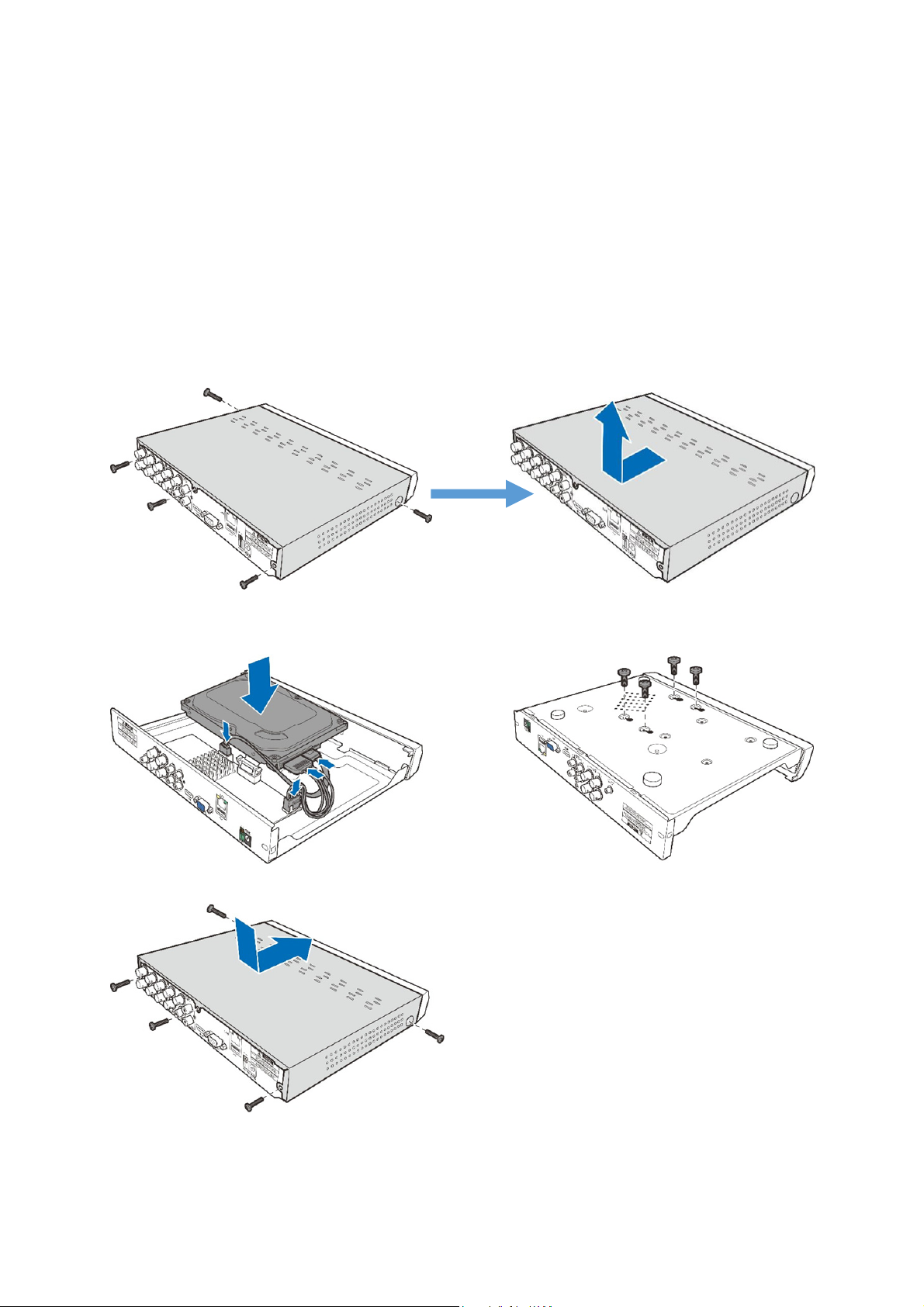
HDD Installation
2.1
Depending on the package you have purchased, the hard disk drive may be included in the full
package. If it is not pre-installed, follow the installation instructions on this user manual.
Caution: DO NOT install or remove the hard disk drive while the device power is turned ON.
HDD Installation:
(1) Cut power firstly, and then remove screws on both sides & rear panel, and open DVR upper cover.
DVR Installation & Connection
(2) Connect the data and power cables to the HDD and place the HDD on the DVR case.
Carefully flip the DVR case and secure the HDD to the DVR with the screws.
(3) Put the upper cover back carefully, and fix the cover with screws.
Note: Above procedures are for reference only. The practical operation may be different
depending on the DVR you purchased.
3
Page 8
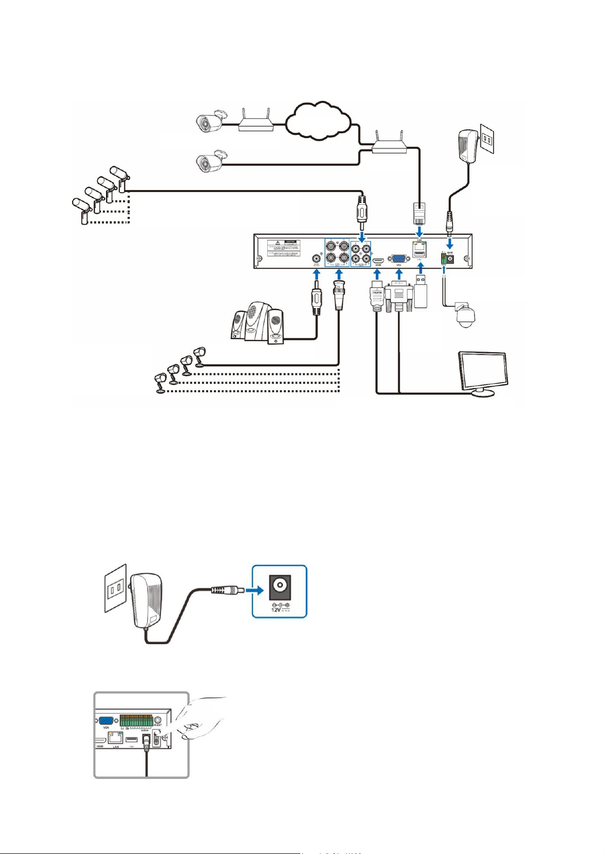
Connection Diagram
2.2
IP Cameras
Microphones
Analog Cameras
Internet
Router
Router
Power Supply
PTZ Control
USB
Speaker
HDMI/VGA to Monitor
Note: Above diagram is for reference only. The practical connection may be different depending
on the DVR you purchased.
Power Supply Connection
2.3
Caution: Use only the supplied power adapter that came with the DVR
Connect one end of the power adapter to the power connector on the back of the DVR. Plug the other
end of the power adapter into the wall outlet.
Wall outlet
Power adapter
For some specific models, you may need to press the Power switch to turn on the power.
4
Page 9
Chapter 3
Using the Supplied Mouse
3.1
Left Button of Mouse Right Button of Mouse
Click once to choose an item in the menus and confirm
your selection.
Click once upon a channel on Live Viewing screen to open
Camera Quick Toolbar
Double-click on the channel on the exit from the menus.
Live Viewing screen to view the channel in full screen mode.
Double-click again to exit the full screen mode.
Click and hold to drag an area on motion mode or adjust
the values of sliders and scales on menu mode.
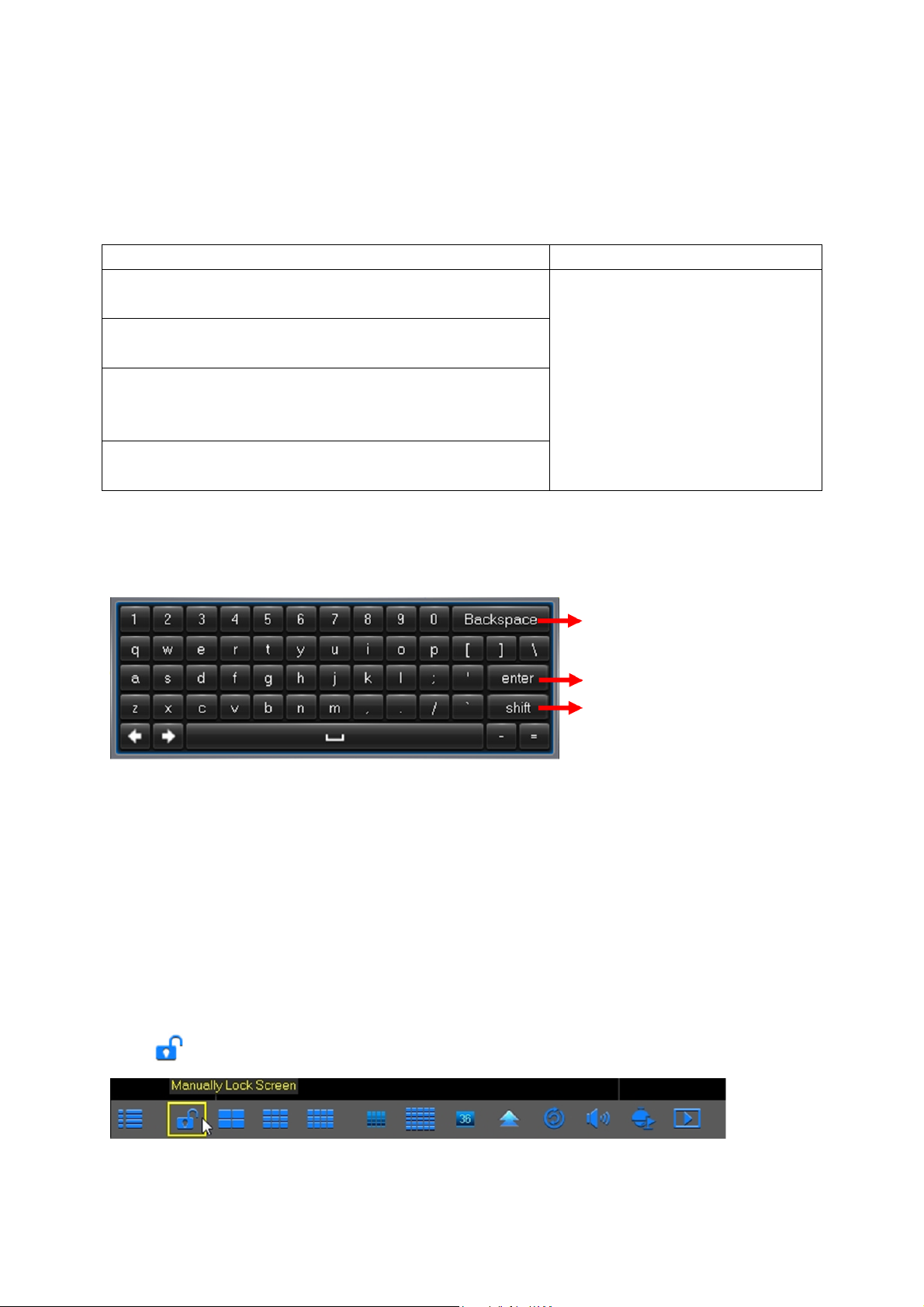
Using the Virtual Keyboard
3.2
You will see the virtual keyboard automatically on the screen anytime you need to enter data
0
DVR Common Operations
Click once to open the pop-up
menu on the Live Viewing screen
and to exit from the menus.
Click to delete a character
Click to enter the text
Click to toggle the keyboard to upper
case and more punctuation
Password & Locking the Screen Operation
3.3
When you run the DVR for the first time, you will be required to set your password immediately in
order to protect your privacy. Please be sure to record your username and password and save
them in a secure place. If you forget your password, you will be unable to login the system, please
contact your reseller to reset the password.
The screen will be locked to protect unauthorized OSD operation while the DVR is not in menu
operation for a while. If necessary, you can also lock the screen operation manually. To do so,
right-click on the Live Viewing screen to make the Pop-up menu bar visible, then click the Lock
icon .
5
Page 10
Chapter 4
Startup Wizard
4.1
After DVR startup is completed, the Startup Wizard will be displayed. Wizard setting menu
includes: Homepage, HDD Management, Network Configuration, Email Configuration, IPC Setup,
Record Schedule and General System Configuration.
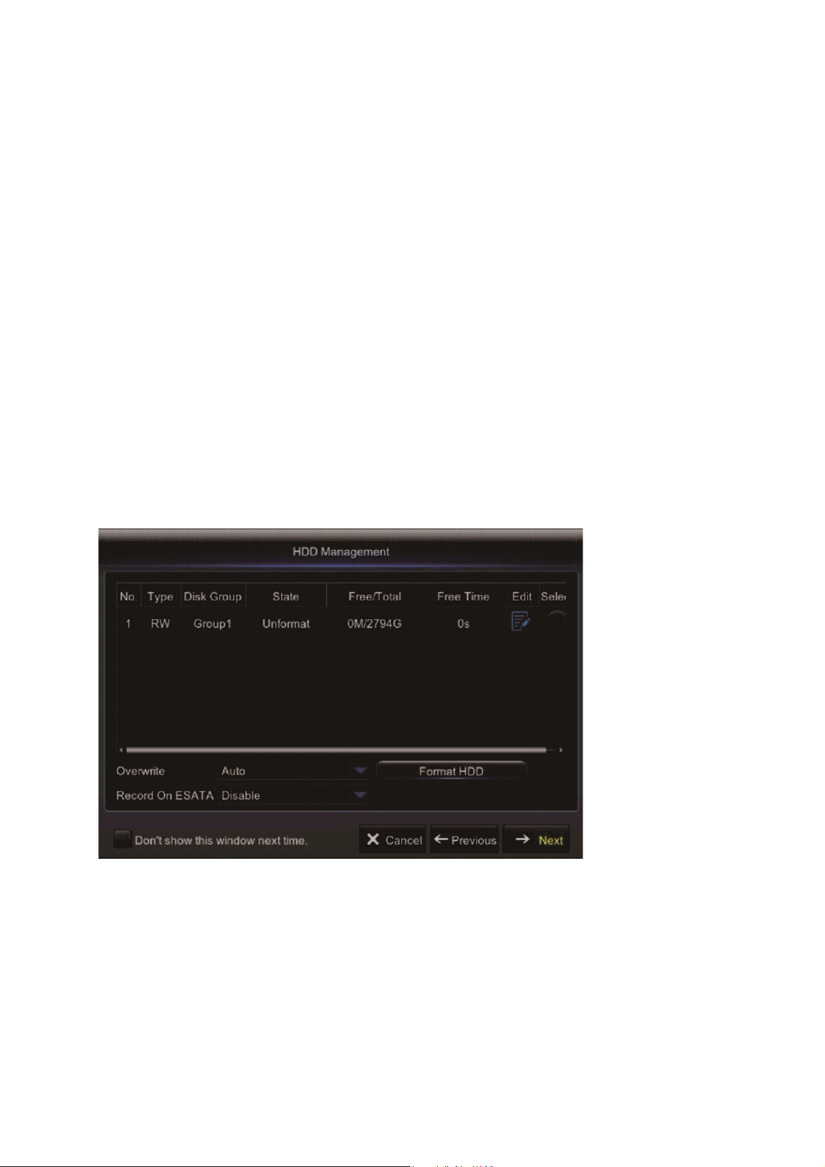
1) Homepage and HDD Management
You can click “Cancel” to skip Start Wizard. Tick “Don’t show this window next time" if you don’t
want to display Start Wizard when system start-up.
If the HDD is installed in the DVR for the first time, it will be needed to be format. Select the HDD
which you want to format, and then click “Format HDD” button to format the HDD.
DVR Starting up
Overwrite: Use this option to overwrite the old recordings on the HDD when the HDD is full. For
example, if you choose the option 7 days then only the last 7 days recordings are kept on the HDD.
To prevent overwriting any old recordings, select Disable. If you have disabled this function, please
check the HDD status regularly, to make sure the HDD is not full.
6
Page 11

2) Network Configuration
This menu allows you to configure network parameters, such as PPPoE, DHCP, Static, and 3G.
The most common types are DHCP or Static. Most probably your network type is DHCP, unless
the network is manually addressed (usually called- Static). If you need an authentication user
name and password to the Internet, then choose PPPoE. If you want to use mobile network
connection, then choose 3G.
3) Email Configuration
This menu allows you to configure email settings. Please complete these settings if you want to
receive the system notifications on your email when a motion is detected, HDD becomes full, HDD
is in error state, or Video Loss occurs, etc.
7
Page 12
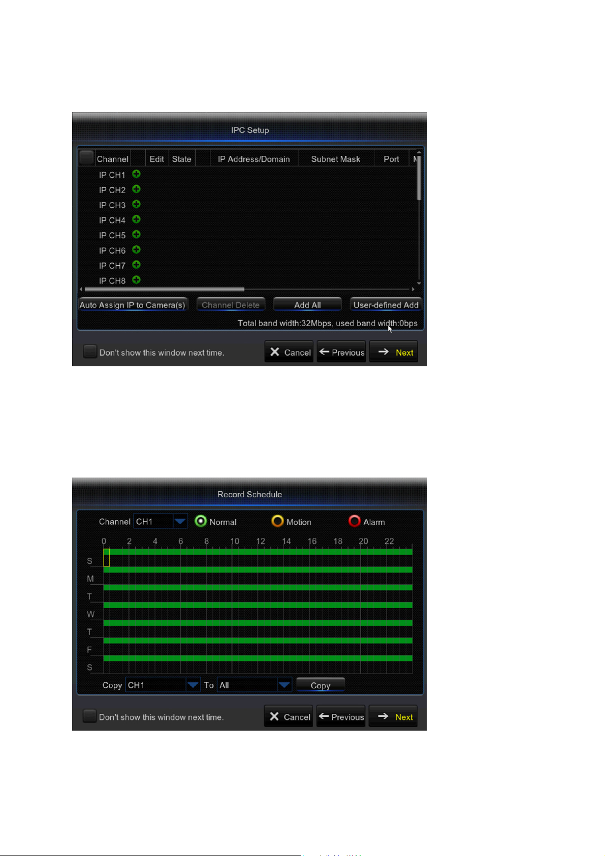
4) IPC Setup
This menu allows you to add and modify IP cameras configurations.
5) Record Schedule
This menu allows you to specify when the DVR records video and define the recording mode for
each channel. The recording schedule lets you set up a schedule like, daily and hourly by Normal
(continuous) recording, Motion recording, and Alarm recording. To set the recording mode, click
first on the mode radio button (Normal, Motion, or Alarm), then drag the cursor to mark the slots.
8
Page 13
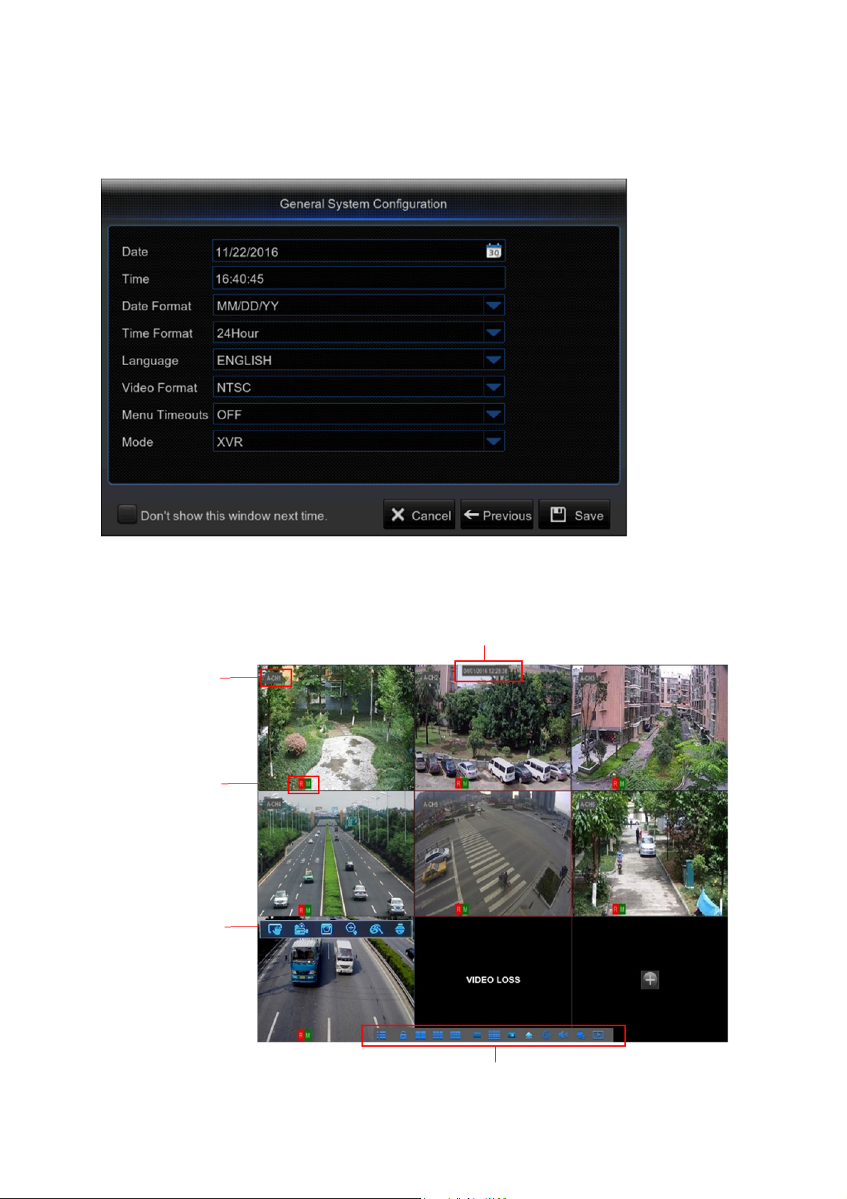
6) General System Configuration
This menu allows you to configure the general parameters of the system, such as Date, Time,
Date Format, Time Format, Language, Menu Timeouts, and Mode.
Live Viewing Screen
4.2
Camera Title
Status Icons
Camera Quick
Toolbar
System Date & Time
Pop-up Menu Bar
9
Page 14
System Date & Time
To display current system date & time
Camera Title
To display the camera title
A-: This indicates that the camera connected is an AHD camera
T-: This indicates that the camera connected is a TVI camera
C-: This indicates that the camera connected is a CVI camera
IP: This indicates that the camera connected is an IP camera
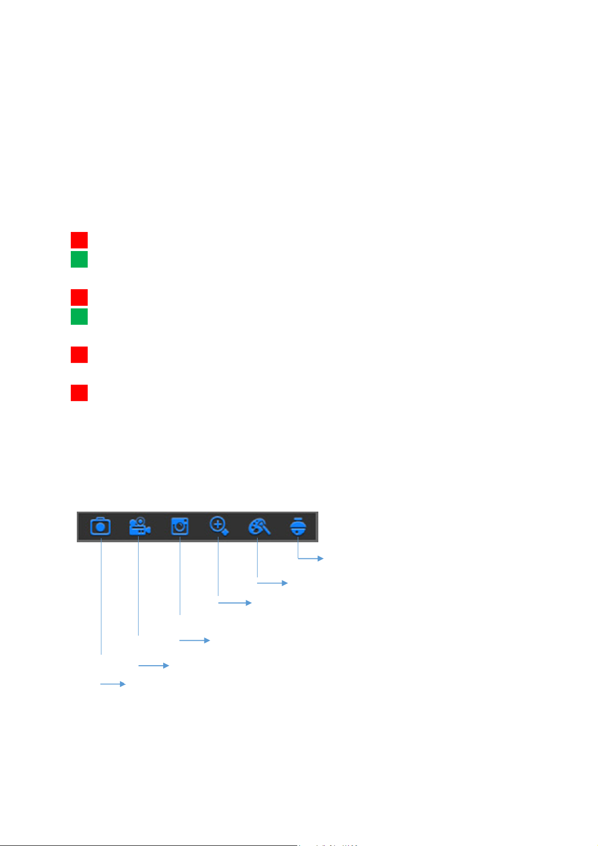
Status Icons
R
This indicates that the DVR is currently recording.
M
The motion icon in Green indicates that the DVR is detecting motion from the camera
but not recording.
M
This icon appears when the camera has detected motion and triggers recording.
I
The I/O alarm icon in Green indicates that the external sensor device is triggered but not
recording.
I
The I/O alarm icon in Green indicates that the external sensor device is triggered for
recording.
H
The HDD icon indicates that the DVR cannot detect a HDD or the HDD is not formatted.
VIDEO LOSS: Connection to the camera has been lost.
Off-line: The added IP camera is offline or disconnected.
No Camera: IP Camera has not been connected to the DVR.
No HDD: HDD is not installed
Camera Quick Toolbar
Click to zoom in the channel
Click to adjust the channel color settings
Click to enter PTZ control panel
Click to playback the recent 5 minutes recording
Click this to manually capture an image
Click to start recording the channel manually
10
Page 15

Pop-up Menu Bar
Click to open the Main Menu
Click to lock/unlock the screen operation
Click to switch to different camera views
Click to view more layout options
Click to switch all IP channels to mainstream or substream (for live view resolution)
Click to switch among real-time, balanced, or smooth view. The view effect modes
influence only the displayed video quality by bit rate and frame rate but do not influence the
recording quality.
Click to start viewing channels in a sequence.
Click to adjust the volume
Click this to start/stop cruise for a PTZ camera
Click to playback videos
Click to view system information
11
Page 16
Overview
5.1
Chapter 5
DVR Menu
E
D
C
B
A
F
G
H
I
K
L M
J
N
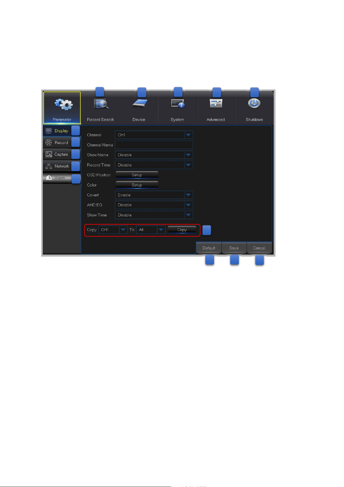
A: Alarm - To set the motion detection function and/or I/O alarm function
B: Network - To configure the DVR’s access parameters to the network, configure email
settings, DDNS parameters, etc.
C: Capture - Image capture configuration
D: Record - To configure the recording options and set the recording schedule
E: Display - To configure how many channels are displayed on the Live Viewing screen, for
example color setup, video output resolution, privacy areas, etc.
F: Record Search - To search for recordings, events, and captured images
G: Device - HDD Management, set the PTZ configuration parameters, and connection
parameters to link your DVR to your Dropbox account.
H: System - To modify general DVR settings, such as date and time, User management,
view system info, etc.
I: Advanced - Advanced settings, for example load default, Firmware update, etc.
J: Shutdown - To shut down or reboot the DVR
K: Copy (Parameters) To - Click to copy the current settings to all channels or one specific
channel
12
Page 17
L: Default - To restore the default settings
M: Save - Click to save the modifications
N: Cancel - Click to discard the modifications
Display
5.2
5.2.1
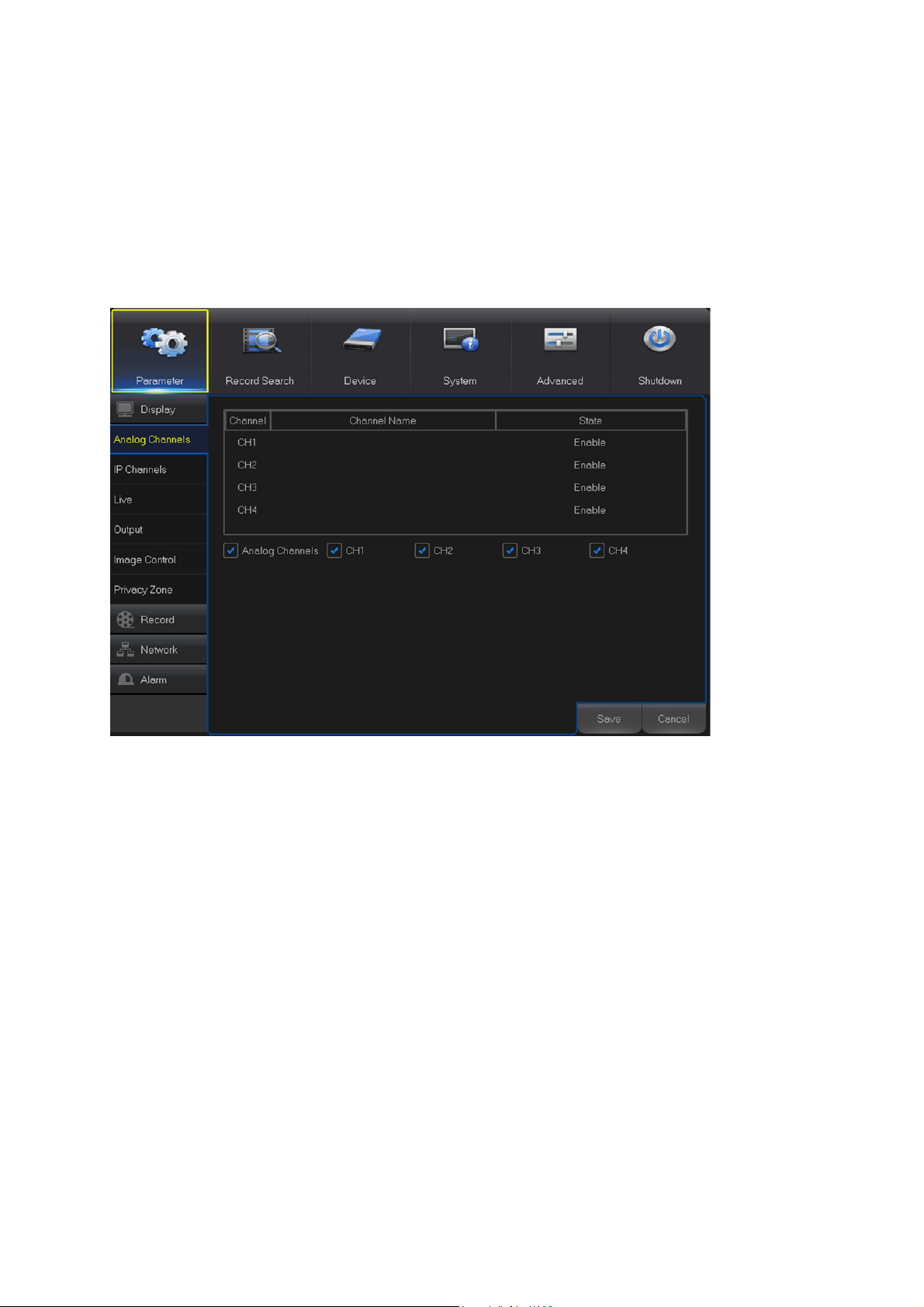
Channel: Display channel identification.
Channel Name: Display the channel name.
State: Display the channel status.
Analog Channel: Click on the checkbox next to the channel identifier to enable or disable the
analog channel. To disable an analog channel can increase an IP channel input.
NOTE: After making modifications to the channel status, click Save to save the changes. You are
prompted to confirm the modifications. Click OK to confirm.
Analog Channels
13
Page 18
5.2.2
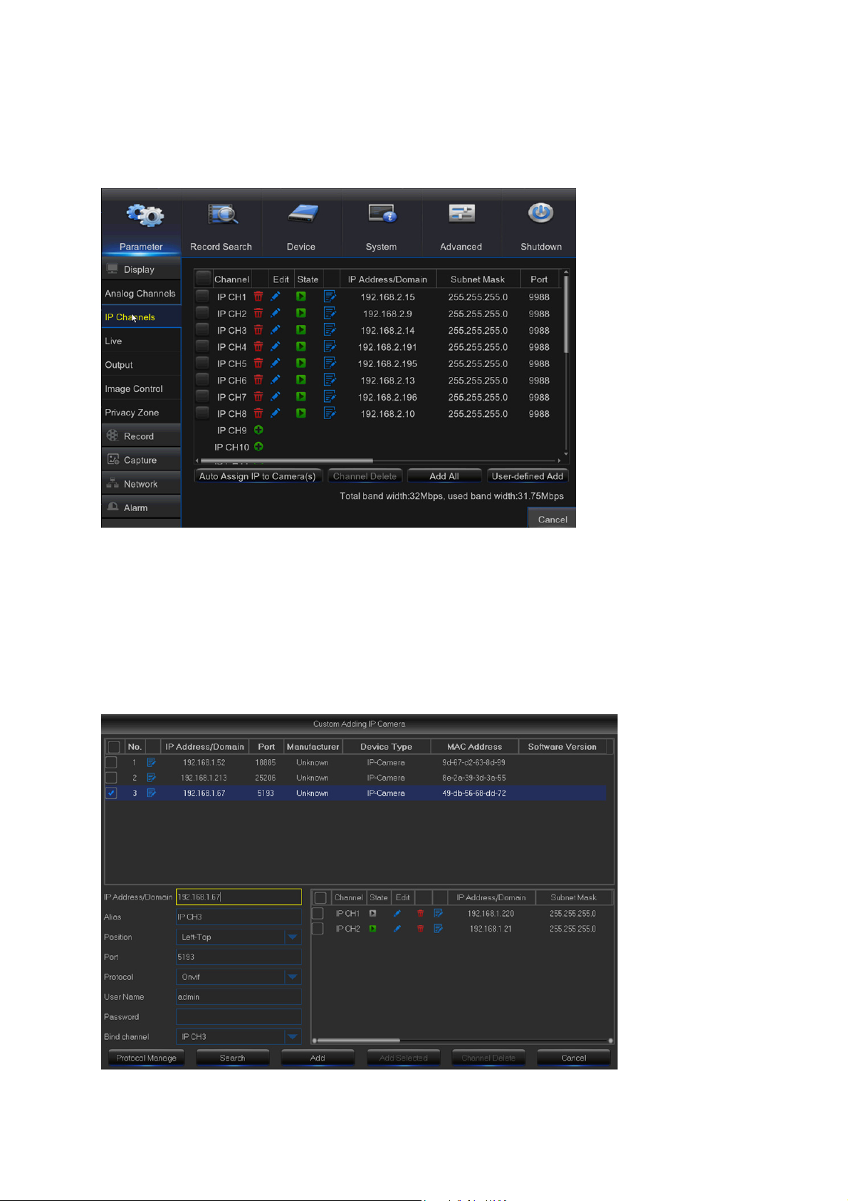
This DVR supports to connect IP camera inputs. In this menu, you can add, edit or delete the IP
cameras.
IP Channels
Auto Assign IP to Camera(s): Click to reassign an IP address to the IP camera that is already
connected to the DVR.
Add All: Click to add local ONVIF cameras (DVR and IP cameras are connected to the same
router). To complete the connection, enter user name and password of the IP camera, and click
OK.
User-defined Add: Click to add remote ONVIF cameras over the Internet.
Enter the connection parameters of the IP camera: IP Address/Domain, Port, Protocol, User
Name, and Password. Then click Add.
14
Page 19
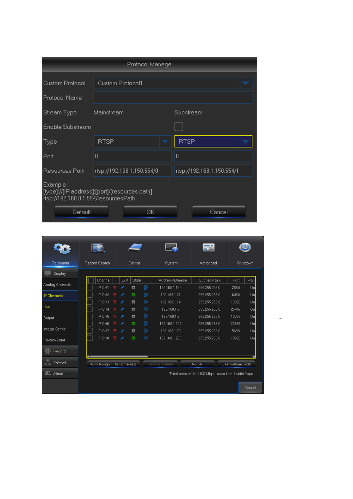
With the Protocol Manage button, you can edit your own RTSP protocol to connect to IP
cameras.
Added IP
Camera List
In the Added IP Camera List, you can view the IP Camera Channel title, Delete IP Camera, Edit
IP Camera, Check the connection State, view the IP address/Domain/Subnet Mask/Port, view
the Manufacturer of the added IP cameras, view the Device Type, check the Protocol, MAC
Address & Software version of IP cameras.
15
Page 20
5.2.3
Live
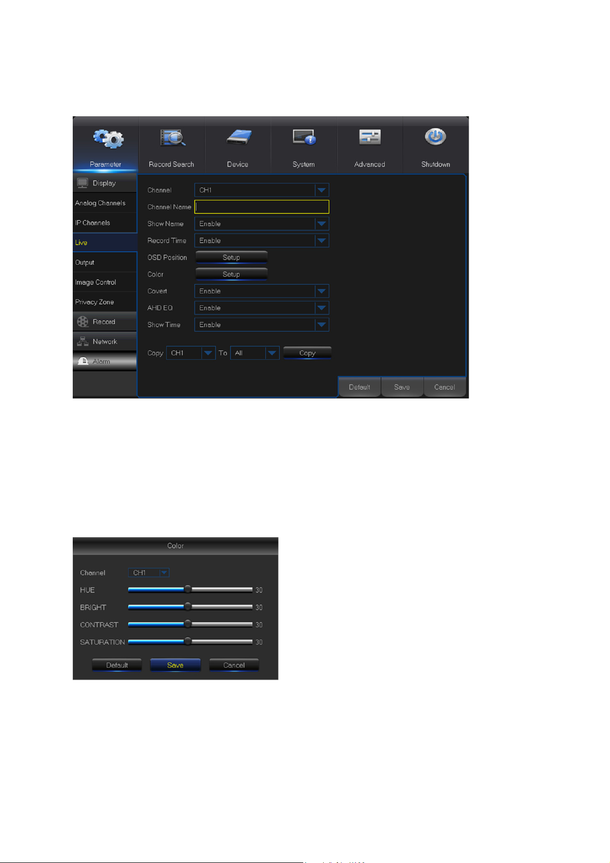
This menu allows you to configure channel parameters.
Channel: Select the channel you want to modify.
Channel Name: Enter the name of the channel.
Show Name: Enable to display the channel name on the live screen.
Record Time: Disable if you do not want to see the recording time on the channel.
OSD Position: Click Setup to determine where you want the channel name and current date to be
displayed when you are viewing the channel. Drag the channel name box and the date/time box to
the desired location on the channel view.
Color: Click Setup to configure video color settings.
HUE: Changes the color mix of the image.
BRIGHT: Defines how bright the image appears on the
display.
CONTRAST: Increases the difference between the darkest
black and the whitest white in the image. Modify the contrast
if the sections of the image look “grey out”.
SATURATION: Alters how much color is displayed in the
image. The higher the saturation, the brighter and vivid colors
will appear to be. Setting this parameter too high can
degrade the image quality.
Covert: Enable if you want to hide this channel from appearing on the Live Viewing screen.
Disabling or enabling this option does not affect video recording on the HDD.
AHD EQ: Enable or disable AHD EQ (Enhanced Quality) function. Configure this parameter if you
are an advanced user.
Show Time: Disable if you do not want the current time to appear on the channel.
16
Page 21
5.2.4
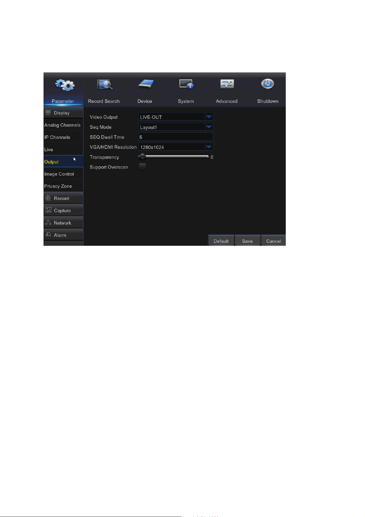
This menu allows you to configure video output parameters
Output
Video Output: This is the monitor that you use for live view display.
Sequence Mode: Choose your favorite layout from the drop-down menu for viewing channels in a
sequence on live view.
SEQ Time: Set how long you want the live view from a channel to be displayed in a sequence.
VGA/HDMI Resolution: Select the highest resolution your monitor/TV supports. The higher the
resolution, the more details you will see on your images. The DVR will restart after you change the
resolution.
Transparency: Decide how transparent you want the menus to be. Choose partially transparent
(see-through) if you need to keep an eye on happenings while adjusting settings.
Support Overscan: Check to adjust the position of the video image on the live viewing screen.
17
Page 22
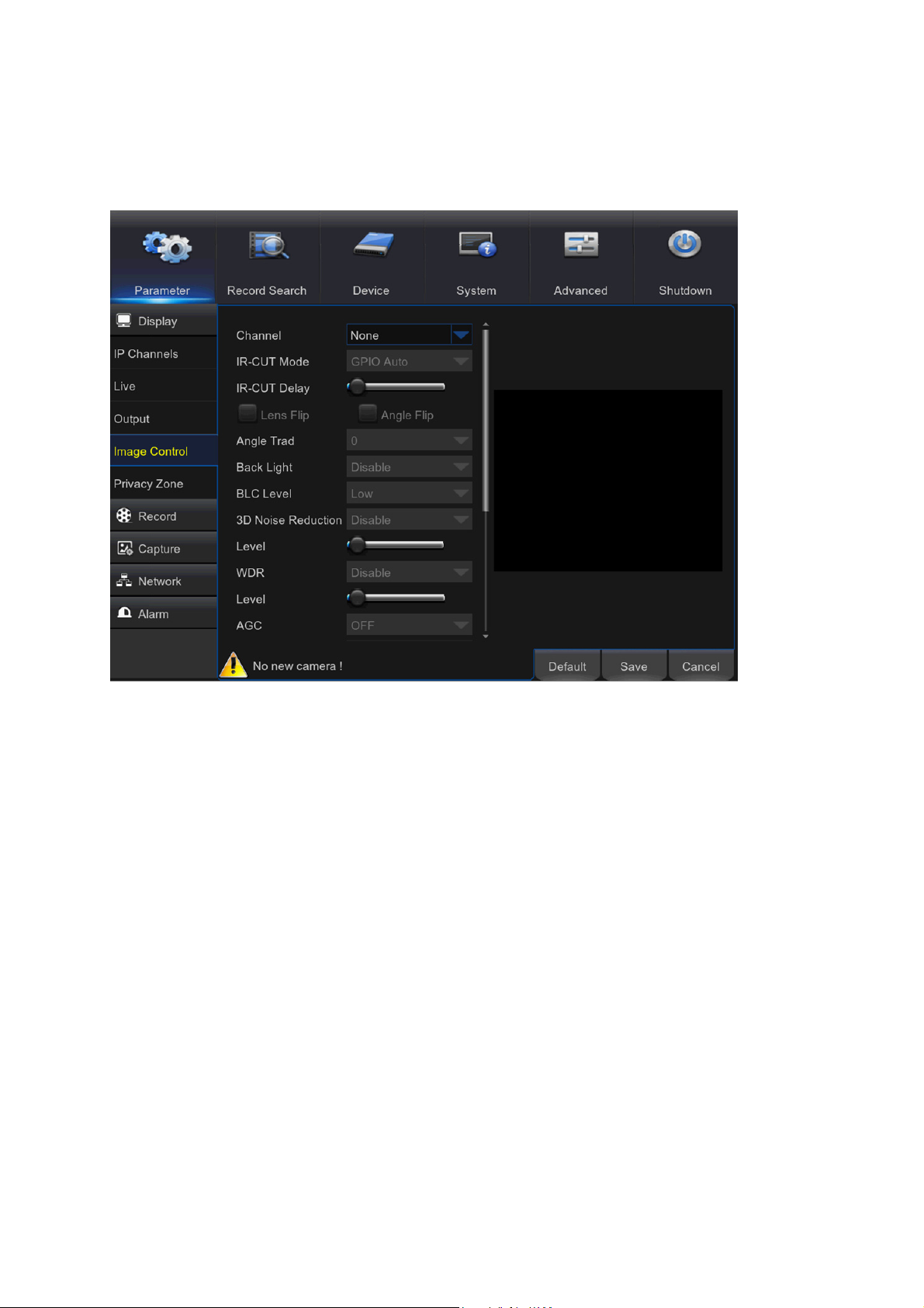
5.2.5
This menu allows you to configure the camera settings. Some IP cameras may not support this
feature and the IP camera settings cannot also be changed using the DVR.
Image Control
Channel: Select the channel you want to modify.
IR-CUT Mode: Select the desired built-in filter switch-over mode to ensure the camera works
properly both in the daylight and night.
IR-CUT Delay: Set the IR-CUT switching time delay.
Lens Flip/Angle Flip: Check to enable automatic lens flip and/or angle flip.
Angle Trad: Set the flip angle.
Back Light: Enable this feature to compensate the darkness of the subject when shooting against
bright light sources. For example, sunlight.
BLC Level: Set the backlight compensation level.
3D Noise Reduction: Enable this feature to digitally minimize video noise and extend the DVR
storage.
Level: Set the noise reduction level.
WDR (Wide Dynamic Range): Enable to allow automatically adjust the brightness and contrast of
the video when shooting in the darkness with bright light sources.
Level: Set the WDR level.
AGC (Automatic Gain Control): Configure when shooting in changing lightning environments. The
video image is brightened in dark areas.
White Balance: Choose the white balance level between Auto (automatic adjustment), Manual
(manual adjustment of red and blue gain), indoor (optimized according to the indoor environment).
Red/Green/Blue: Adjust the red/green/blue value.
Shutter: Set the shutter mode.
18
Page 23
Time Exposure: Choose the exposure time of the camera.
Defog Mode: Use in foggy environments to improve the video quality.
Level: Set the defog level.
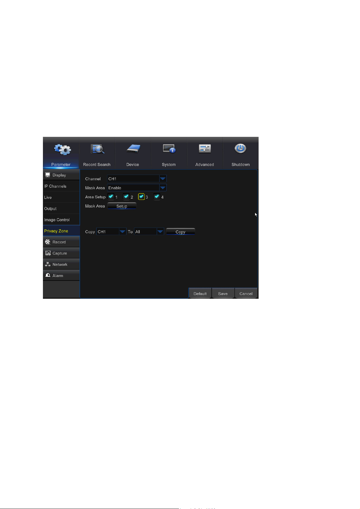
5.2.6
This menu allows you to create Privacy Zone(s) if you want to partially cover up part of the image.
You can create up to four privacy zones in any size and location on the channel view. These
zone(s) appear as “red box rectangle areas”. Just click inside the default red-lined rectangle and
drag it where you want to create a privacy zone.
Private Zone
Select the Channel where you want to set privacy zone(s), then Enable Mask Area. Decide how
many privacy areas you want to set and check the area(s) in Area Setup, and click Setup to open
the channel in full screen mode and start marking the privacy zones.
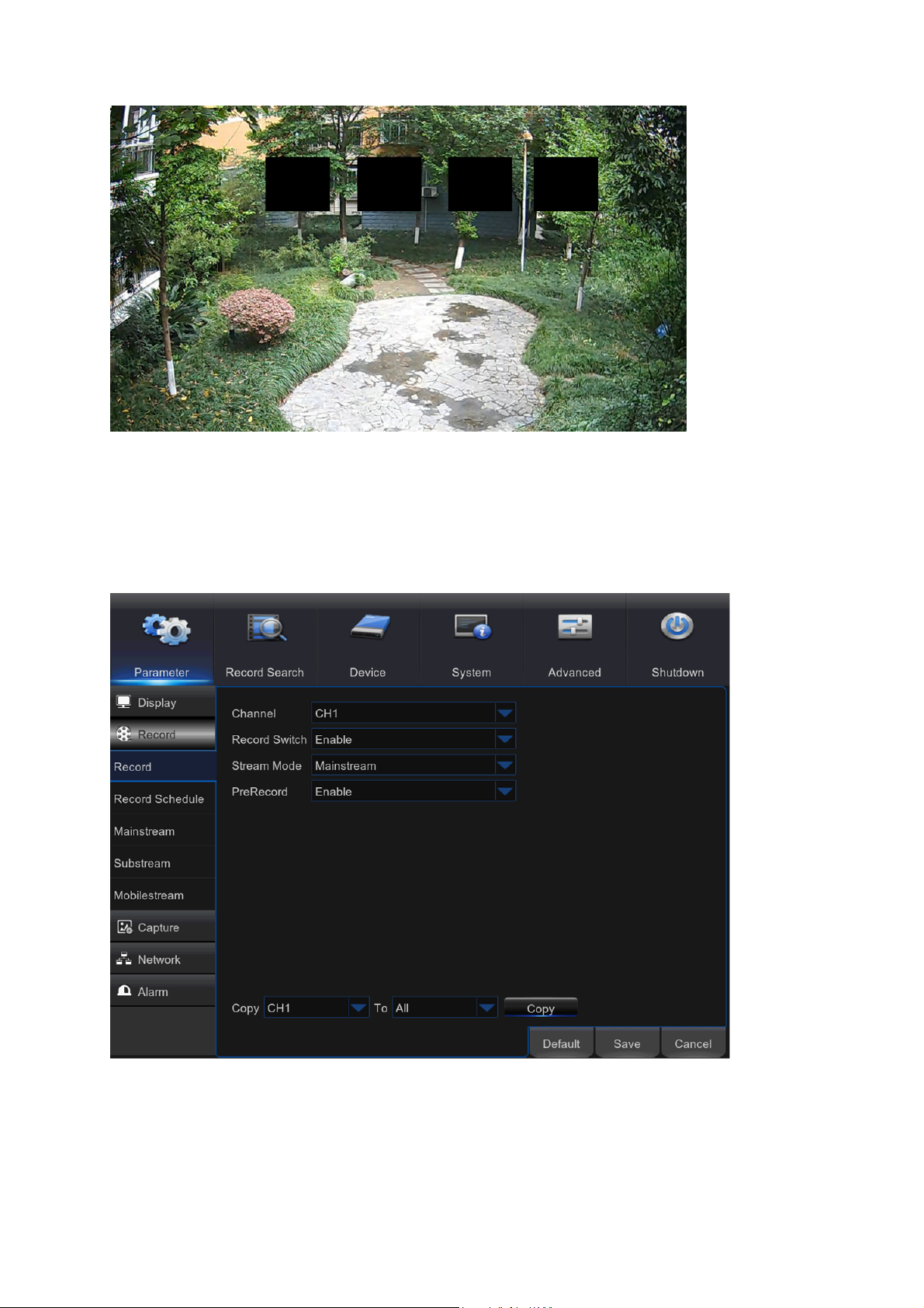
Depending on the number of areas you have chosen in Area Setup, you will see areas covered
with black rectangles on the channel view. When you have finished marking the areas, right-click
to return to the Main Menu.
19
Page 24
Record
5.3
5.3.1
This menu allows you to configure the channel recording parameters.
Record
Channel: Select the channel to set its recording parameters.
Record Switch: Enable in order to allow the video to be recorded to the HDD.
20
Page 25

Stream Mode: Choose the recording resolution. The available options are Mainstream and
Substream.
PreRecord: If this option is enabled, the DVR starts recording a few seconds before an event
occurs. Use this option if your primary recording type is motion based.
5.3.2
This menu allows you to specify when the DVR records video and define the recording mode for
each channel. The recording schedule lets you set up a schedule like, daily and hourly by normal
(continuous) recording, motion recording, and alarm recording. To set the recording mode, click
first on the mode radio button (Normal, Motion, or Alarm), then drag the cursor to mark the slots.
The recording schedule is valid only for one channel. If you want to use the same recording
schedule for other channels, use Copy To function.
Record Schedule
Channel: Select the channel to set its recording parameters.
Normal: When the time slot is marked green, this indicates the channel performs normal recording
for that time slot.
Motion: When the time slot is marked yellow, this indicates the channel records only when a
motion is detected during that time slot.
NOTE: To use the motion detection, you must enable and configure the motion settings for the
channel in Alarm menu. Please see 5.6.1 Motion
Alarm: When the time slot is marked red, this indicates the channel records only when the sensor
is triggered during that time slot.
No Record: A time slot marked black means that there is no recording scheduled for the time slot.
21
Page 26

5.3.3
This menu allows you to configure the recorded video parameters. All the modifications you apply
to these settings will affect the recorded video saved into the HDD.
Mainstream
Channel: Select the channel to configure recording related information.
Resolution: This parameter defines, how large the recorded image will be.
FPS: This parameter defines the number of frames per second the DVR will record.
Bitrate Control: Select the bitrate level based on the complexity of the scene. For a simple scene,
such as a gray wall is suitable constant bitrate (CBR). For more complex scene, such as a busy
street is suitable variable bitrate (VBR).
Bitrate Mode: If you want to set the bitrate by yourself, then choose User-defined mode. If you
want to select the predefined bitrate, choose Predefined mode.
Bitrate: This parameter corresponds to the speed of data transfer that the DVR will use to record
video. Recordings that are encoded at higher bitrates, will be of better quality.
Audio: Select this option if you want to record audio along with video and have a microphone
connected to the DVR or using a camera with audio capability.
22
Page 27

5.3.4
This menu allows you to configure the settings of a particular channel if the channel is being
viewed via remote access, for example Web Client.
Substream
Channel: Choose the channel where the settings are applied.
Resolution: Set the resolution.
FPS: This parameter defines the number of frames per second at the remote session.
Bitrate Control: Select the bitrate level based on the complexity of the scene. For a simple scene,
such as gray wall is suitable constant bitrate (CBR). For more complex scene, such as busy street
is suitable variable bitrate (VBR).
Bitrate Mode: If you want to set the bitrate by yourself, then choose User-defined mode. If you
want to select the predefined bitrate, choose Predefined mode.
Bitrate: Enter manually or choose from the drop-down menu the data throughput during the
remote session.
Audio: Tick the box if you want to hear the live sound at the remote session. Make sure the
camera with audio capability is properly connected to the selected channel.
23
Page 28

5.3.5
This menu allows you to configure the settings of a particular channel if the channel is being
viewed via mobile devices.
Mobile stream
Channel: Choose the channel where the settings are applied.
Enable: Enable to allow to use mobile streaming on this channel
Resolution: Set the resolution.
FPS: This parameter defines the number of frames per second at the mobile session.
Bitrate Control: Select the bitrate level based on the complexity of the scene. For a simple scene,
such as gray wall is suitable constant bitrate (CBR). For more complex scene, such as busy street
is suitable variable bitrate (VBR).
Bitrate Mode: If you want to set the bitrate by yourself, then choose User-defined mode. If you
want to select the predefined bitrate, choose Predefined mode.
Bitrate: Enter manually or choose from the drop-down menu the data throughput during the
mobile session.
Audio: Tick the box if you want to hear the live sound at the mobile session. Make sure the
camera with audio capability is properly connected to the selected channel.
24
Page 29

Capture
5.4
This menu allows you to configure the snapshot capturing parameters.
Channel: Select the channel to set its capture parameters.
Auto Capture: Enable or disable automatic capturing on the channel. When this feature is
enabled, you can select the snapshot capturing interval.
Stream Mode: Select the image resolution.
NOTE: When the Auto Capture is enabled, you can select the image capturing interval.
Normal Interval: Snapshots are captured based on normal interval.
Alarm Interval: Snapshots are captured based on alarm interval only when a motion is detected
or sensor is triggered.
Manual Capture: Enable or disable manual capturing on the channel.
25
Page 30

Capture Schedule
Channel: Select the channel to set its snapshot capturing schedule.
Normal: When the time slot is marked green, this indicates the channel is capturing snapshots
based on the Normal Interval.
Motion: When the time slot is marked yellow, this indicates the channel is capturing snapshots
based on Alarm Interval only when a motion is detected.
Motion: When the time slot is marked red, this indicates the channel is capturing snapshots based
on Alarm Interval only when a sensor is triggered.
No Capturing: A time slot marked black means that there is no snapshot capturing scheduled for
the time slot.
26
Page 31

Network
5.5
This menu allows you to configure Network parameters, E-mail setup, DDNS, RTSP & FTP.
5.5.1
This menu allows you to configure network parameters, such as PPPoE, DHCP, Static, and 3G.
The most common types are DHCP or Static. Most probably your network type is DHCP, unless
the network is manually addressed (usually called- Static). If you need an authentication user
name and password to the Internet, then choose PPPoE. If you want to use mobile network
connection, then choose 3G.
Network
Network Type: Select the network type you are using.
PPPoE: This is an advanced protocol that allows the DVR to connect to the network more directly
via DSL modem.
DHCP: This is the network type when a device on your network (usually a router) assigns
automatically all the network parameters for your DVR.
Static: Requires all the network parameters to be filled in manually.
3G: Prior using the mobile network, you need to connect a 3G dongle to the DVR.
HTTP Port: This is the port that you will use to log in remotely to the DVR (e.g. using the Web
Client). If the default port 80 is already taken by other applications, please change it.
27
Page 32

Client Port: This is the port that the DVR will use to send information through. If the default port
9000 is already taken by other applications, please change it.
IP Address: The IP address identifies the DVR in the network. It consists of four groups of
numbers between 0 to 255, separated by periods. For example, “192.168.001.100”. You need to
enter the IP address manually only if your network type is Static.
Subnet Mask: Subnet mask is a network parameter which defines a range of IP addresses that
can be used in a network. If IP address is like a street where you live then subnet mask is like a
neighborhood. The subnet address also consists of four groups of numbers, separated by periods.
For example, “255.255.000.000”. Alike IP address, you need to enter the subnet mask manually
only if your network type is Static.
Gateway: This address allows the DVR to access the Internet. The format of the Gateway
address is the same as the IP Address. For example, “192.168.001.001”. Alike IP address, you
need to enter the gateway address manually only if your network type is Static.
DNS1/DNS2: DNS1 is the primary DNS server and DNS2 is a backup DNS server. Usually should
be enough just to enter the DNS1 server address.
UPNP: If you want to log in remotely to the DVR using Web Client, you need to complete the port
forwarding. Enable this option if your router supports the UPnP. You need to enable UPnP both, on
DVR and router. In this case, you do not need to configure manually port forwarding on your router.
If your router does not support UPnP, make sure the port forwarding is completed manually
28
Page 33

5.5.2
This menu allows you to configure email settings. Please complete these settings if you want to
receive the system notifications on your email when a motion is detected, HDD becomes full, HDD
is in error state, or Video Loss occurs.
E-mail
Email: Enable this feature.
Encryption: Enable if your email server requires the SSL or TLS verification. If you are not sure,
set to be Auto.
SMTP Port: Enter the SMTP port of your email server.
SMTP Server: Enter the SMTP server address of your email.
User Name: Enter your email address.
Password: Enter the password of your email.
Receiver 1~3: Enter the email address where you want to receive the event notifications from the
DVR.
Interval: Configure the length of the time interval between the notification emails from the DVR.
To make sure all settings are correct, click Test Email. The system sends an automated email
message to your inbox. If you received the test email, it means the configuration parameters are
correct.
29
Page 34

5.5.3
The color codes on email schedule have the following meanings:
Green: Slot for Motion.
Yellow: Slot for I/O Alarm.
Red: Slot for Exception (HDD full, HDD error, or Video Loss).
E-mail Schedule
5.5.4
This menu allows you to configure DDNS settings. The DDNS provides a static address to simplify
remote connection to your DVR. To use the DDNS, you first need to open an account on the
DDNS service provider’s web page
DDNS
DDNS: Enable the DDNS service.
30
Page 35

Server: Select the preferred DDNS server (DDNS_3322, DYNDNS, NO_IP, CHANGEIP, DNSEXIT).
Domain: Enter the domain name you created on the DDNS service provider’s web page. This will
be the address you type in the URL box when you want to connect remotely to the DVR via PC.
Fox example: dvr.no-ip.org.
User/Password: Enter the user name and password you obtained when creating an account on
the DDNS service provider’s web page.
After all parameters are entered, click Test DDNS to test the DDNS settings.
5.5.5
The DVR can be remotely viewed via RTSP protocol.
RTSP
RTSP Enable: Enable/Disable
Verify: Enable/Disable
RTSP Port: Default is 554, if the default port 554 is already taken by other applications, please
change it.
Analog Channel: rtsp://IP: Port/chA/B
A: 01 (ch1), 02 (ch2)….16 (ch16)
B: 0 (main stream), 1 (sub stream)
For example, the DVR IP address is 192.168.1.120, and you want to view CH1 with mainstream,
then the RTSP address will be: rtsp: //192.168.1.120: 554/ch1/0
31
Page 36

Note: RTSP user name and password is same with DVR user name, password and permissions.
Follow the instruction to input IP and port to preview video.
5.5.6
This menu allows you to enable FTP function to view and load captured snapshots from DVR to
your storage device over FTP.
FTP
FTP Enable: Enable the feature in DVR.
Server IP: Enter your FTP server IP address or domain name.
Port: Enter the FTP port for file exchanges.
Name/Password: Enter your FTP server user name and password.
Directory Name: Enter the default directory name for the FTP file exchanges.
Test FTP: Click to test the FTP settings.
32
Page 37

Alarm
5.6
In these section, you can configure the Motion Detection, I/O Alarm & PTZ Linkage.
5.6.1
This menu allows you to configure motion parameters. The motion detection is pretty straight
forward, the DVR simply compares one frame to another. A sufficient amount of difference is
interpreted as motion. When the motion is detected, the system can be set to automatically initiate
recording. In this menu you can select the channels where you want the motion detection
recording to take place.
If you set the motion detection at a high sensitivity level (“8” is the most sensitive) then the
frequency of false alarm events increases. If the sensitivity level is too low (“1” is the least
sensitive), you might increase the risk that a significant motion event will not trigger the motion
detection to record.
Motion
Channel: Select the channel you want to set the motion detection.
Enable: Enable or disable the function.
Buzzer: The DVR can use its internal buzzer to emit an alarm tone. You can set the buzzer
duration in seconds when the motion is detected.
Sensitivity: Set the sensitivity level.
Area: To setup motion area, click Setup.
33
Page 38

By default, the whole screen is marked for motion detection (red blocks). If you want to disable the
motion detection on an area, you need to click the grid cursor and then drag the mouse to highlight
the scope to unmark the area (transparent block). After setting is completed, right click the mouse
button to return and click Save to make the area setup effective.
Motion Detection Area Setup
Post Recording: You can set how long after an event occurs that the DVR will continue to record.
Area is unmarked
The recommended recording length is 30 seconds but it can be set higher up to 5 minutes.
Alarm Out: Optional function. If your DVR support to connect to external alarm device, you can
set to emit an alarm tone.
Latch Time: To configure the external alarm time when motion is detected.
Show Message: Check the box to display “M” icon on the screen when the motion is detected.
Send Email: You can let the DVR to send you an auto-email when the motion is detected.
Full Screen: If this function is enabled and a motion is detected in a channel, you will see that
channel in full screen.
Analog Channels/IP Channels: Here you can select which channels you want to include to the
motion detection. If the motion is detected, the recording will start immediately on those channels.
5.6.2
This is an optional function. If the DVR you purchased doesn’t support connect external sensor I/O
alarm devices, you will not find this section in your DVR OSD menu.
Alarm
34
Page 39

Alarm In: User may set four groups of alarm inputs
Alarm Type: There are 3 types for your choice: Normally-Open, Normally-Close, and OFF.
Choose the one to match your sensor type, or Choose OFF to close the sensor trigger function.
Latch Time: you can set how long the buzzer will sound when external sensor is triggered (10s,
20s, 40s, and 60s).
Buzzer: The DVR can use its internal buzzer to emit an alarm tone. You can set the buzzer
duration in seconds when a sensor is triggered.
Post Recording: You can set how long alarm record will last when alarm ends (30s, 1minutes,
2minutes, 5minutes).
Alarm out: Tick to enable external alarm device to emit an alarm tone when a sensor is triggered.
Show Message: Display the alarm messages on the screen when sensor is triggered.
Send Email: Set to send email to specified email when sensor is triggered.
Full Screen: When sensor is triggered, the corresponding channel will be switched to the full
screen mode.
Analog Channels/IP Channels: Select which channels you want to record when sensor is
triggered.
35
Page 40

5.6.3
If you had connect the PTZ cameras, you can set the linkage between PTZ cameras and Motion
Alarm and/or external I/O sensor alarm. With the linkage function, you can turn your PTZ cameras
focus to the preset point when a motion or I/O alarm happens.
PTZ Linkage
Channel: Select the channel to set.
Switch: Enable or disable the PTZ linkage function.
Alarm Type: Choose what kind of alarm will trigger the PTZ linkage function.
PTZ: Associates the PTZ camera with preset points. View preset point at 5.8.3.1 PTZ control
36
Page 41

Record Search & Backup
5.7
This section allows you to search and playback the recorded videos based on recording type,
channel, date and time parameters. You can also view and backup events and captured images.
5.7.1
General
1) Select the channel & the recording type (All/Normal/Alarm (including preset point & IO)/
Motion/IO/Manual).
2) Determine the recording date.
3) Click Search.
4) Select the recording from the table.
NOTE: Dates marked with orange triangles have video recordings.
5) Select the channels you want to playback.
6) Modify the start time and end time if necessary and then click Play.
Enter the playback interface, to view 5.7.4 Playback Video Recordings
37
Page 42

5.7.2
This section is used to check the recording file lists and make backup.
Events
Select the recording
1)
Select the
2)
Click
3)
If you want to make backup for all recording files you had searched, click
4)
If you want to make backup for individual files, select the recording list(s) from the table.
5)
If you want to move to other page, click << or >> to move to previous or next page. Or input the
6)
number of page, then click to jump to the page.
After selecting the files, click
7)
your backup files: original H.264, AVI and MP4. The total size of the backup files will be
displayed, please make sure not to exceed the available capacity of your USB flash device.
Channel
Search.
Date & Time.
and
Typ e
(All/Normal/Alarm (including Motion & IO)/Motion/IO).
Quick Backup.
Backup
to start the backup. There are 3 kinds file formats for
38
Page 43

Note: Please make sure you have inserted your USB flash device to the DVR USB port before you
want to make backup.
8) If you want to Lock the recoding files, tick the checkbox after the files. The locked files will be
protected and unable to be overwritten if you had enable the HDD Overwrite function.
5.7.3
This section is used to view the captured pictures and make backup.
Picture
Select the recording
1)
Select the
2)
Click
3)
If you want to make backup for all captured you had searched, click
4)
If you want to make backup for individual files, select the picture lists from the table.
5)
If you want to move to other page, click << or >> to move to previous or next page. Or input the
6)
number of page, then click to jump to the page.
After selecting all files, click
7)
Note: Due to the system limitation, only max. 5000 captured pictures will be searched & shown.
If you want to view a captured picture, please double click a picture from the list, the system view
turn to picture play mode. Right click your mouse to exit the play mode.
Channel
Search.
Date & Time.
and
Typ e
(All/Normal/Alarm (including Motion & IO)/Motion/IO/Manual).
Backup
Quick Backup.
to start the backup.
39
Page 44

Backward Play, click again to pause
Forward Play, click again to pause
Move to previous page
Move to next page
Single picture display
Quad pictures display
Nine pictures display
40
Page 45

5.7.4
1. Recording Calendar: Dates marked with orange triangles have recordings.
2. Playback Type: Select the playback type among General, Events, Picture & Sub-periods
3. Channels: Check the channels to playback.
4. Playback Control Bar
Playback Video Recordings
1
○
2
○
3
○
4
○
5
○
6
○
9
○
7
○
8
○
Full Screen
Fast Rewind: x2, x4, x8 and x16
Slow Play: 1/2, 1/4 and
1/8 speed
Play & Pause
Pause, Play frame by frame
Stop
5. Time Bar:
- Motion recording (Yellow)
- Smart recording (Dark Green)
- Normal recording (Green)
- I/O sensor recording (Blue)
- Alarm recording (Red)
6. Time Frame: Select Playback timeline. View 5.7.4.3 Time Frame
7. Smart Search: Please see more in 5.7.4.1 Smart Search
8. Recording Type Indicator: Motion, Smart, Normal, and IO & Alarm.
9. Recording Playback Screen: Video recordings from selected channels.
The color indicates the video recording type:
Fast Forward, x2, x4, x8 and x16
Digital Zoom: Click to zoom in
Trim Video: view 5.7.4.2 Trim Video
Volume Control: Slide the slider bar
to increase or decrease volume.
Click to mute audio.
41
Page 46

5.7.4.1 Smart Search
Use this function to find motion of a specific area inside recording. It supports to search a single
channel every time.
1. Select a channel to playback in full screen.
2. Click the smart search icon , the system will enlarge the channel into full screen and
display the smart search quick toolbar. You can move the toolbar by dragging the icon.
3. Use the cursor to mark the area on the channel where you want to find motion or click
to search motion all over the screen.
4. Click to start search.
42
Page 47

5. As a result of Smart Search, you will see the motion based recording(s) on the channel
Time Bar marked with
Dark Green
lines.
5.7.4.2 Trim Video
Use this function if you need to backup just a certain section of the video recording.
Connect a USB flash drive to the DVR.
1)
Double-click on the channel (to display in full screen during video playback) that you wish to
2)
backup.
Click on the Time Bar to mark the beginning of the video footage you wish to backup.
3)
Click to start selecting the footage.
4)
Click on the Time Bar to mark the end of the video footage you wish to backup.
5)
The marked up area is now displayed within the red arrows.
Click to save the footage.
6)
A video type selection message appears. Select the file format and click
7)
Save.
43
Page 48

5.7.4.3 Time Frame
During video playback, the time bar is displayed in 24 Hours (00: 00~24: 00) by default.
You can shorten the time bar to be displayed in 2 Hours, 1 Hour or 30 Minutes in order to make an
accurate position to the time bar.
5.7.4.4 Sub-periods Playback
This function will allow you to divide a recording video into average separate segments and play
together in the same screen.
1) In the video playback interface, choose Sub-periods from Playback Type section.
2) Select a channel you want to play.
3) Choose the Split Screens. If you have a 4 Channel DVR, the max. split screens will be 4. And
8 for 8 Channel DVR as well 16 for 16 Channel DVR.
For example, if the video you want to play is 60 minutes in length, and the split screen is 4, the
video will be divided in to 4 segments, and each segment will be 15 minutes in length. All the 4
segments will be played in the same screen.
44
Page 49

5.7.5
This section will help you to play the backup files.
1) Install the Video_Player software in the CD and run.
Play Backup Files
2) Copy the backup files to your computer.
3) Click “+” or “Open File” button to add files. It supports to play rf, avi, mp4, 264 & 265 files.
45
Page 50

Function Description:
Play: Click to play file
Pause: Click to pause.
Stop: Click to stop playback.
Frame Forward: step forward by frame
Slow forward: Click to play at 8x, 4x, 2x, 1x, 1/2, 1/4, 1/8, 1/16 speed.
Fast forward: Click to play at 16x, 8x, 4x, 2x, 1x, 1/2x, 1/4x, 1/8x speed
Open file/Open Directory
Expand/pack up the list.
Screenshot: Save path: C: \Users\Administrator\VideoPlayer\picture
Cut: Save path: C: \Users\Administrator\VideoPlayer\video
Full screen display
Never on top
Always on top
On top during playing
Adjust volume
Window Division
1/4/9/16 channels optional.
Add folder or file.
Playback mode, Single, Order, Repeat one, Repeat ALL are optional
Delete all files in the list.
Search File
Language/Settings
46
Page 51

Basic Settings: Set on-top mode
Capture Settings: Set the path to save images
47
Page 52

Device
5.8
In this section, you can configure the internal HDD, PTZ setup & Cloud storage.
5.8.1
This menu allows you to check & configure the internal HDD that the DVR uses for saving the
recordings. You need to format the HDD only at the first startup and if you replace the HDD.
HDD
Format HDD: Select the HDD you want to format and then click Format HDD. To
start formatting, you need to enter your user name and password and then click OK to
confirm to continue formatting.
Overwrite: Use this option to overwrite the old recordings on the HDD when the HDD
is full. For example, if you choose the option 7 days then only the last 7 days
recordings are kept on the HDD. To prevent overwriting any old recordings, select
Disable. If you have disabled this function, please check the HDD status regularly, to
make sure the HDD is not full. Recording will be stopped if HDD is full.
Record on ESATA: This menu only displayed when your DVR is coming with an
e-SATA port on the rear panel. It will allow to record the video to external e-SATA
HDD to enhance your HDD capacity.
Note: If the eSATA recording function is enabled, eSATA backup function will be
disabled.
48
Page 53

5.8.2
S.M.A.R.T
This function will help to check the HDD health. Please note that due to the system limitation, your
DVR may not have this function.
If you want to continue to use the HDD if S.M.A.R.T self-check find an exception, tick the item “Self-check not
passed, continue to use the HDD”.
Select “HDD ID”, select “Self-check Type”, click Check to start the test. Self-check State will display the result.
Note: If an HDD S.M.A.R.T error if found, the HDD can be continued to use, but there will be a risk to lose video
recording. It is recommended to replace by a new HDD.
49
Page 54

5.8.3
This menu allows you to configure the PTZ (Pan-Tilt-Zoom) settings for the dome camera.
PTZ Setup & Control
Channel: Choose a channel where is connected a dome camera.
Protocol: Choose the communication protocol between the PTZ capable camera and DVR. If
your camera support UTC (Up the Coax) function, you can choose COAX1 or 2 to display your
camera OSD menu or control the UTC PTZ function.
Baudrate: The speed of the information sent from the DVR to the PTZ-capable camera. Make
sure it matches the compatibility level of your PTZ-capable camera.
DataBit/StopBit: The information between the DVR and PTZ-capable camera is sent in individual
packages. The DataBit indicates the number of bits sent, while the EndBit indicates the end of the
package and the beginning of the next (information) package. The available parameters for
DataBit are: 8, 7, 6, 5. the available parameters for the StopBit are 1 or 2.
Parity: For error check. See the documentation of your PTZ-capable camera, to configure this
setting.
Cruise: Enable to allow to use the Cruise mode. In order to use the Cruise mode, you need to set
a number of preset points.
Address: Set the command address of the PTZ system. Please be noted that each PTZ-capable
camera needs a unique address to function properly
50
Page 55

5.8.3.1 PTZ control
After finishing the PTZ setup, you can use the PTZ function to control your PTZ camera.
1) Left click your mouse upon a channel on Live Viewing screen to open Camera Quick Toolbar,
and click the PTZ control icon .
2) PTZ control panel will be displayed. Click to active PRESET points setup page.
1 2 3 4 7 8 9
13
5
14
6 10 11 12
No. Icon Item Description
1
2
3
4 Speed Speed Adjust the PTZ speed
5
Channel Click to select the channel of the PTZ camera.
Start/stop PTZ cruise by preset points. Make sure you had
Cruise
UTC Menu
Pointer Panel
enable the Cruise function for this channel in
5.8.3 PTZ Setup & Control
If you have choose protocol for this channel as COAX1 or
COAX2, the UTC menu button will be display. Click this icon
to enter UTC OSD menu. Also used to confirm your selection
in the UTC OSD menu.
A) Click the direction arrow to select the direction of the PTZ
camera
B) Click up/down/left/right arrow to move cursor in UTC OSD
menu
C) Click to switch to auto pan mode
51
Page 56

- ZOOM + Zoom Click to zoom in/out.
6
- FOCUS + Focus Click to adjust the focus
- IRIS + Iris Click to adjust the iris setting
7
8 No No. Number of preset point
9 Total Total Display the total number of preset points
10 Time Time Set the time how long the camera will stay in the preset point
11 Save Save Click to save the settings and preset points
12 Clear Clear Click to delete the selected preset point
13 GO_TO Go to
14 Set Set
PRESET To display or hide the preset point panel
Enter the number of a specific preset point, click this button to
move your PTZ camera to the preset point
Click to set a specific preset point on a PTZ camera.
You can add up to 255 preset points for the DVR. However,
the actual preset quantity varies depending on the PTZ
camera performance.
5.8.4
This menu allows you to see what is happening on your camera site anytime, anywhere through
the Internet. Uploading the snapshots can be based on a time interval or a motion is detected.
Cloud Storage
Cloud Storage: Enable to allow cloud settings
Cloud Type: Only Dropbox cloud storage is supported currently
Channel: Select the channels where you want to upload the snapshots to Dropbox
Time trigger: Set the image uploading interval. Set OFF if you want to use motion based
uploading
52
Page 57

Motion Detection: Enable if you want to upload snapshots to Dropbox when the camera detects a
motion
Drive Name: Enter the cloud storage name for your DVR
Activate Cloud: Click to activate the function. An activation email will be sent to the Receiver
email account
Advanced E-mail Setup: Click to configure your email settings
Upgrade Cloud Storage: Click to upgrade the current cloud storage service
Process to start uploading the snapshots
1) Enable Cloud Storage and configure Cloud settings for channel(s).
2) Configure advanced e-mail settings in Advanced E-mail Setup.
3) Click Activate Cloud and wait for the verification email.
4) Click Activate Cloud in Dropbox link on verification email.
NOTE: Make sure to check your email and follow the link to complete cloud storage activation
within 3 minutes.
5) Enter your Dropbox account credentials.
Setting up the Cloud service is now complete. If you encountered any problems while activating
the Cloud service, please repeat steps from 3 to 5.
53
Page 58

System
5.9
You are able to configure general parameters of the system, such as date and time, OSD
language, menu timeouts, DST, NTP, User Management, check system information & system log
here.
5.9.1
General
Date/Time: Enter the date and time manually.
NOTE: For date/time automation over the Internet, enable NTP.
Date Format: Set the date format here.
Time Format: Set the time format here.
Language: Choose the OSD language.
Video Format: Choose the video format between NTSC and PAL. If the DVR’s picture is flickering
or has only black screen, it may be that the video format is not correct.
Menu Timeouts: Set the time out the DVR will exit the menus when they are not in use.
Mode: XVR or DVR. XVR model will allow you to add IP Cameras to the DVR. DVR mode will
focus on basic analog cameras.
Note: If Mode changed from XVR to DVR, all added IP cameras will be deleted.
Show Wizard: Check if you want the Startup Wizard to reappear each time you start up the DVR.
Note: After Mode switch to DVR, all IPC information will be hidden and automatically restored to
factory settings.
54
Page 59

5.9.2
DST stands for Daylight Savings Time.
DST: Enable if Daylight Saving Time (DST) is observed in your region
Time Offset: Select the amount of time to offset for DST
Daylight Saving Time: Choose to set the daylight saving time in weeks or in days
Start Time/End Time: Set the start time and end time for daylight saving
DST
5.9.3
NTP stands for Network Time Protocol. This feature allows you to synchronize the date and time
automatically on the DVR over Internet. Therefore the DVR needs to be connected to the Internet.
NTP: Enable if you want the DVR to update the date and time automatically.
Server Address: Select the NTP (Network Time Protocol) server.
Time Zone: Select the Time Zone in your location.
Update Time: Click here to update the system date and time immediately.
NTP
55
Page 60

Note: When NTP function is enabled, system will update the system time at 00: 07: 50 every day,
or every time when the system is started up.
5.9.4
This menu allows you to configure the user login information.
Edit: To enable/disable the user account, modify the user name and password, click on the user
account you wish to edit, then click Edit.
Users
56
Page 61

Permission: To modify user access permissions, click on the user account you wish to modify,
then click Permission. The user in Admin level has all permissions to the system. After modify the
permissions, click Save to save the modifications.
5.9.5
This menu allows you to view the summary of the system, channel information & record
information
Info
57
Page 62

Device Name: Enter the desired name for your DVR. The name can include both letters and
numbers.
Device ID: Enter the desired ID for your DVR. The device ID is used to identify the DVR, and can
only be composed of numbers, and cannot be the same with other IDs when multiple DVRs are
connected in the same network.
MAC Address: Display the MAC address of the DVR. When multiple DVRs are connected to the
same network, each DVR must have a unique MAC address to ensure that the DVR can connect
to the network.
Note: If your DVR support P2P function, you will find a QR code in the info page. You can scan
this QR cord with mobile app to remote access this DVR, view more on Chapter 7 Remote
Access via Mobiel Devices.
Channel Info: To view the information summary on the channels.
Record Info: To view the recording information summary by channel, record state, stream type,
FPS, bitrate, and resolution.
5.9.6
This menu allows you to view a list of events of system operation.
Log
- To search for a log, enter the start time/end time to the respective fields and click Search.
- To display log details, double-click on the item.
- To backup a log entry, connect an external USB disk to the DVR, click on the log event and click
Backup.
Log Type: Select the log type.
58
Page 63

Start Time/End Time: Specify the start and end date/time of the logs you want to review and/or
save on an external USB storage device. Click Search. The logs will be listed on the table.
5.10
This menu allows you to configure automatic system maintenance, load factory defaults, update
the firmware settings, upgrade the IPC, etc.
5.10.1
Advanced
Maintain
Default User: If you want to log in to the DVR automatically for live view after each startup, then
only administrator user account can be set for auto login.
Auto Reboot: Set enable to reboot the DVR based on a schedule.
Reboot: Set the rebooting schedule based on day, week, or month.
Update: Click to load the update file and then upgrade the firmware. Please do NOT power off the
DVR or remove the USB during the upgrading.
Load Settings: Select this option to import the setting that you have saved earlier, using the Save
Settings function.
Load Default: Use this feature to restore the factory default settings of the DVR. It is
recommended to load defaults for all options, after upgrading the firmware.
Save Settings: Select this option to save the DVR current settings, such as the video recording
settings, network configurations, and etc. to the USB device.
IPC Load Default: Use this feature to restore the factory default settings of IP cameras.
Reboot IPC: To reboot IP cameras.
59
Page 64

IPC Upgrade: To upgrade IP cameras firmware. Some IP cameras may not support this feature.
5.10.2
This menu allows you to set the type of events that you want the DVR to inform you.
Events
Event Type: Select the event type. Options are:
- Disk Full: When HDD is full.
- Disk Error: If HDD is not detected properly.
- Video Loss: If camera is not detected properly.
Enable: Check the box to enable the monitoring of the event.
Show Message: Check the box to display a message on the screen when Disk Full, Disk Error, or
Video Loss event happens.
Send Email: Let the DVR to send you an auto-email when an event occurs.
Alarm Out: Click to enable the external alarm device to sound. This is an optional function.
Latch Time: Determine how long the external sensor alarm device to sound (10s, 20s, 40s, 60s).
Buzzer: Set the buzzer duration when the event occurs (Off/10s/20s/40s/60s). To disable buzzer,
select OFF.
60
Page 65

5.11
Manually turn off or reboot the DVR.
Shutdown
You will need to input your user name and password to complete the operation.
61
Page 66

Chapter 6
Use the Web Client to remotely access your DVR at any time via a PC. Before you access the
Web Client, you need to ensure that the network settings of the DVR are configured properly. The
most convenient and easiest way is if you have set the DVR a static IP address (please see
“5.5.1 Network”). It means you only need to open the web browser on your PC and type in the
static IP address you have set on the DVR. However, if the IP address of the DVR is assigned by a
DHCP server (see “5.5.1 Network”), then it means that each time you reboot the DVR, the IP
address changes. In this case, ask if your ISP can provide you a static IP address. If not, then
configure the DDNS service. See the network settings in “5.5.4 DDNS”.
Remote Access via Web Client
System Environment Requirements
The minimum requirements for hardware and OS required to run Web Client are given as below.
Item Minimum Recommended
CPU Intel i3 Intel i7 or higher
RAM 4G or more 8G or more
Hard Drive 500G or more 1000G or more
Display RAM 2G or more 4G or more
Display Resolution 1280*1024 1920*1080
OS Windows® Vista, Windows® 7, Windows® 8 Mac OS X® 10.9 and above
DirectX DirectX 11
Direct3D Acceleration Function
Ethernet Adapter 10/100M Ethernet Adapter
IE Microsoft Internet Explorer (Ver. 11, 10, 9, 8)
Mozilla Firefox 43.0.4 or above
Google Chrome V44 or below
Mac Safari 5.1 or above
Web Plugin Download and Installation
6.1
To access the Web Client, do the following:
For IE/Chrome/Firefox:
1) Launch the explorer on your PC and enter the DVR static IP address or DDNS domain name
(Host Name) you have set on DVR in the URL box.
62
Page 67

2) For the first time you run the web client, system will require to install the web client plugin.
Click download to download the plugin and install to your computer.
3) After installing the plug-in, close & launch again your browser and repeat step 1 to open the
login page. Input your user name and password to login the web client.
Note:
need to enable NPAPI plugins. Please enter chrome: //flags/#enable-npapi on URL bar to find and
enable NPAPI. It doesn’t support V45 or above so far.
If you use Google Chrome, please use Version V41 or below. If you use V42 to V44, you
63
Page 68

For Mac SAFARI:
1) Launch the Safari on your Mac, and enter the DVR static IP address or DDNS domain name
(Host Name) you have set on DVR in the URL box.
2) Download the plug-in “SurveillanceClient.dmg”, locate the downloaded file and double click it.
3) Click on “Continue” --> “Install”. Enter user name and password for Mac computer,
Click on “Install Software” --> “Close” to finish installation.
2
1
3
4) Close SAFARI repeat step 1 to open the Web Client login page.
64
4
Page 69

Web Client Manager
6.2
The web client supports to full control the DVR with administrator account. Please make sure to
protect your user name & password for preventing illegal login.
6.2.1
This is the first screen that opens after you have logged in to the Web Client. Here you can open or
close live preview, record video to local computer manually, take snapshots of the screens, PTZ
control, color adjustment, etc.
Live Interface
1. Buttons on a single live interface:
: Volume switch
: Record switch: the remote record switch of client. Record will be automatically saved
to a specified position on PC after the function is enabled.
: Snapshot: Capture the selected live image and save it to a specified position on PC.
The image is saved as *.bmp format.
: Digital ZOOM.
: Open the images on Live window.
: Close all the Live channels
: Switch display mode in channel window
65
Page 70

: Open the images on Live window.
: Stretch.
: Original proportions.
: Click to maximize the current window to full screen. Right click to popup menu option
and select Exit Full Screen.
2. Video Control
Hue: Adjust the chromaticity of video
Bright: Adjust the brightness of video
Contrast: Adjust the contrast of video
Saturation: Adjust the saturation of video
66
Page 71

3. PTZ Control
: PTZ direction control and automatic scanning button
: PTZ movement speed adjustment
: Adjust the zoom +, -
: Adjust FOCUS +, -
: Adjust the IRIS +, -
: Set, clear and jump points
: Start cruising and stop cruising
6.2.2
You can search & play recorded files stored on the HDD inside the DVR, and save the result to the
local directory on your PC.
Playback
Click to enter into Playback interface to remotely view the records in DVR HDD.
It supports 1 to 4 channel record playback.
67
Page 72

1. Record Search
Record playback procedure
Firstly, select the date you want to check and tick 1 to 4 channels. Any record files in current
channel at current date will be displayed in the status bar of the interface.
Secondly, select record type (Normal record, Alarm record and All) and channels, and then click
“ ”, and time axis panel will display specific time quantum. On the time axis,
red part stands for alarm record, yellow stands for normal record and original part stands for no
record during this period.
Before playback, choose to enable playback 4 channels synchronously. If you tick-select
“ ”, that means the selected channel will playback synchronously;
otherwise, you could separately control the channels playback.
Thirdly, start playback
Click to start record playback. When mouse curse is moving on the time axis, the time point
of current position will be displayed on the time axis screen. Click to locate the record. Click the
icon or to zoom in/out the time bar display ratio.
68
Page 73

Sub-stream playback
“Stream” select “SubStream”, select the channel, click “ ” search video, click “ ” play.
2. Playback Control
Playback control bar.
Detailed brief description is shown as below list
Key
Description Key
Play
Pause
Stop
By frame
Record Clip
Enable the volume switch
Slow playing 1/2,1/4, 1/8,
Description
Volume adjustment bar
Fast playing 1/2/4/8
Digital ZOOM
Original proportions
playback channels
Snap
Download
Open all the
Stop playing all the playback
69
Stretch
Full Screen
Page 74

Record file clip
After opening playback, click icon to clip the selected file; and click again to stop the clip
function. Then playback clip is successfully done. Record clip file will be saved as *.264 format.
Snapshot function
Move the mouse curse to the channel you want to capture, and click [] icon to capture the live
images remotely. After capturing the images successfully, a path prompt box will be popped up.
The captured file will be saved as .bmp format.
Record file download
Click download icon “ ” on the control bar to display all the matched record file according to
the search conditions of channels.
Tick-select the record file you want to download and click [Start download]. System will download
the record file in sequence and save to local PC. The downloading file will be displayed in
percentage form. After downloading finishes, “Complete” will be displayed on the status bar.
Tip: The recorder supports HTTP, if there is network disconnection during the download, continue
to download from the file point before disconnecting when the network recovers.
70
Page 75

6.2.3
Here you can remotely configure the settings of the DVR. Please see “Chapter 5 DVR Menu” for
more information.
Remote Setting
6.2.4
Record Path: Set the path to save manual recordings on your PC’s local drive.
Download Path: Set the path on your PC’s local drive where you want to download recordings
from the DVR.
Snapshot Path: Set the path to save manual snapshots on your PC’s local drive.
Save: Click Save to save the modifications.
File Type: Choose your preferred file type for manual recordings.
Interval: Determine the maximum length of manual recordings.
Local Setting
71
Page 76

Chapter 7
Troubleshooting
7.1
1. Q: What can I do if the system does not detect the HDD?
A: Check if the power supply system is properly connected and data cord and power cables
are securely connected, and if something wrong with the HDD interface. Or you may check if
your HDD is supported by referring to the specifications or descriptions.
2. Q: I have changed the password but forget the new password, how can I access the system?
A: If you forget system password, please consult with our technical personnel. We strongly
suggest user to set password easy to be remembered and relatively safe. If you have safety
requirement, please do not set very simply password, such as 000000.
3. Q: We see abnormal video signal or even no video signal by connecting the DVR and camera
together. Power supply for both devices is OK. What is wrong?
A: Check network cable at DVR side to see if the cable is firmly connected and if it is worn out
and needs to be replaced, or to check if NTSC or PAL is selected consistently.
4. Q: How to prevent DVR from being influenced by heat?
A: The DVR needs to dissipate heat while it is running. Please place the DVR in a place with
good air circulation and away from heat sources to ensure stability and life of the DVR.
5. Q: The remote controller of DVR doesn’t work while the monitor screen is OK and panel keys
are functional. Why?
A: Operate again by aiming the remote controller at the IR receiver on front panel. If it still
doesn’t work, please check if the batteries in the remote controller are dying. If not, check if
the remote controller is broken.
6. Q: I want to take out HDD from my PC and install it in DVR. Can it work?
A: All HDDs supported by the system can be used. But remember, once DVR runs, the data
on your HDD will be lost.
7. Q: Can I playback while recording?
A: Yes. The system supports the function of playing while recording.
8. Q: Can I clear some records on HDD of DVR?
A: In consideration of the file security, you may not clear part of records. If you want to remove
all the records, you can format HDD.
9. Q: Why can’t I log in DVR client?
A: Please check if the network connection settings are correct and RJ-45 port is with good
contact. And check if your account and password are correctly input.
10. Q: Why can’t I find any records during playback?
A: Please check if the data line connection for HDD is OK and system time is properly
adjusted. Try a few times and restart. If it still doesn’t work, check if the HDD is broken.
11. Q: Why DVR cannot control PTZ?
A: Please check if:
a) PTZ in the front side is malfunctioned.
b) Setting, connection and installation of PTZ decoder are not correct.
Appendix
72
Page 77

c) PTZ setting of DVR is not correct.
d) Protocol of PTZ decoder does not match that of DVR.
e) Address of PTZ decoder does not match that of DVR.
f) If many decoders are connected, the farthest side of AB line of PTZ decoder should be
added 120Ω resistance to realize reflection suppression and impedance matching.
Otherwise, PTZ control will be unstable.
12. Q: Why doesn’t dynamic detection work?
A: Please check if the motion detection time and motion detection regional setting are correct
and if the sensitivity is set too low.
13. Q: Why doesn’t alarm work?
A: Please check if the alarm setting, alarm connection and alarm input signals are correct.
14. Q: Why does buzzer keep alarming?
A: Please check the alarm setting, check if motion detection function is enabled and object
motion is detected all the time and if I/O alarm is set as Always Off. Besides, refer to
corresponding HDD alarm setting.
15. Q: Why can’t I stop recording by pressing “STOP” button or click “Stop Recording” in context
menu?
A: Pressing Stop or Stop Recording can only stop manual record. If you want to stop
Scheduled recording in certain time quantum, please change the setting to No Record. To
stop Startup recording, please change record mode to scheduled recording or manual
recording. Then you may stop recording by the prescribed methods. And another way of
stopping recording is to set channel as off status in record setting.
Usage Maintenance
7.2
1. To shut down DVR, please firstly shut down the system and then turn off the power. Do not
turn off the power directly or HDD data will be lost or damaged.
2. Please keep DVR away from heat sources or places.
3. Clean the internal dust regularly. Make sure the good ventilation of DVR so as to ensure the
good heat dissipation.
4. Please do not hot plugging audio and video cables, or cables connected to ports like RS-232
or RS-485. Otherwise the ports will be damaged.
5. Please check the HDD cable and data cable regularly to see if they are ageing.
6. Please prevent the audio and video signals of DVR from being intervened by other electronic
devices, and prevent the HDD from being damaged by static electricity and induced voltage. If
the network cable is frequently plugged, it is suggested to replace connecting line regularly, or
the input signal may be unstable.
7. This is a class A product. It maybe bring wireless interference in life. Under this situation, it
need user to make measures.
73
Page 78

Accessories (For reference only)
r
r
7.3
□ Remote Controlle
□ USB mouse □ CD
Hereby ASSMANN Electronic GmbH, declares that this device is in compliance with the requirements
of Directive 2014/30/EU (EMC), Directive 2014/35/EU (LVD) and the Directive 2011/65/EU for RoHS
compliance. The complete declaration of conformity can be requested by post under the below
mentioned manufacturer address.
Note:
If wrongly installed or improperly used in the living area, the device can cause interference in radios
and other electronic devices. Appropriate use is when the device, as far as feasible, is operated with
shielded connection cables (with network products in addition to category 5 shielded cables and higher).
The device has been tested and falls within the limits of class A computing equipment according to the
requirements of EN 55032.
Warning:
This device conforms with test category A - it can cause radio interference in the living area; in this case
the operator may demand that appropriate measures are implemented and arise for this reason.
Declaration of conformity: The device fulfills the EMV requirements according to EN 55032 for ITE and
EN 55024 class A. In this way, the fundamental protection requirements of the EMV-2014/
guideline are fulfilled.
www.assmann.com
Assmann Electronic GmbH
Auf dem Schüffel 3
58513 Lüdenscheid
Germany
□ Power Adapte
□ Warranty Card
30/EU
74
Page 79

The material in this document is the intellectual property of our department.
No part of this manual may be reproduced, copied, translated, transmitted, or published in
any form or by any means without our department prior written permission.
Our products are under continual improvement and we reserve the right to make changes
without notice. But no guarantee is given as to the correctness of its contents.
We do not undertake any responsibility for the harms cause by using our product.
The model of the products in the user's manual only for recognition, but these names also
perhaps are belong to other company's registered trademark or the copyright.
The product picture may differ from the actual product, only for your reference. The
accessories will probably be different according to the different selling areas. For details of
accessories, please refer to your local distributor.
Copyright reserved
 Loading...