

Page 1
4CH AHD Digital Video Recorder kit
with 4x 720P outdoor fixed Lens cameras
Quick Installation Guide
DN-16120
Page 2
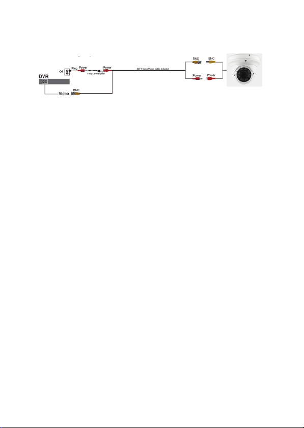
Connect directly to your DVR
Connecting your cameras to your DVR:
1. Find the 60ft. BNC cable, 1-to-4 camera power splitter cable, power adapter,
and the cameras from the package.
2. Locate the end of the 60ft. BNC cable labeled “TO CAMERA” and connect the
yellow BNC adapter on the 60ft. BNC cable to the yellow BNC adapter on the
camera.
3. Connect the red RCA power adapter on the cable to the red RCA power adapter
on the camera.
4. Locate the end of the 60ft. BNC cable labeled “TO DVR”.
5. Connect the yellow BNC adapter on the 60ft. BNC cable to channel input on the
back of the DVR. The channel inputs are labeled by number.
6. Connect the red RCA power adapter on the 60ft. BNC cable to the male side of
the 1-to-4 camera power splitter cable. Keep in mind the cable should be
plugged into the side that has the four adapters.
7. Repeat steps 1-7 for all cameras.
8. Connect the power adapter to the female side of the 1-to-4 camera power splitter
cable. Keep in mind the cable should be plugged into the side that has only one
adapter.
9. Plug the power adapter into a wall socket or a surge protector.
Your cameras are now connected and are ready to start recording.
NOTE:
Connect the cameras and cables to the DVR before mounting to ensure that they work
properly.
Page 3

Note: In case of incorrect installation and improper use in a r esidential area, the
interference to radio devices and other electronic devices could be caused.
It is recommended to use the device where appli cable with shielded cables (also shielded with
networking products of cable Category 5e and higher). The device was tested to comply with the limits
for Computer and IT accessories of Class A according to the requirements of EN 55022.
Warning: This product complies with the test class A - It may be used in the living area but could cause
radio interference; in this case, it may be demanded by the operator t o take appropriate corrective
action at his/her own expense.
Declaration of Conformity:
The device meets the EMC requirements according t o EN 55022 class A and EN 55024 for ITE
category with external or built-in power suppl y to meet the requirements of EN 61000-3-2 and EN
61000-3-3 according to the EMC Directive 2004/108/EC. The declaration of Conformity can be
requested by post at the following manufacturer address.
www.assmann.com
ASSMANN Electronic GmbH
Auf dem Schüffel 3
58513 Lüdenscheid
Germany
Page 4

di
g
s
e
m
a
a
D
7
s
g
e
A
O
r
2
o
k
v
a
itale
in
klusiv
Kurz
4-k
AH
4 x
it fe
nleitu
-Vid
20P
tem
ng zu
D
N-161
nali
es,
orec
ußen
bjekti
Instal
0
amer
lation
rder
Kit
s
Page 5

Direkter Anschluss an Ihren DVR
r
DVR
Stecker
ode
4-Wege Kamerasplitter
BNC
Video
18 Meter Video-/Netzkabel im Lieferumfang enthal ten
Stromversorgung
Stromversorgung Stromversorgung Stromversorgung
Anschluss der Kameras an Ihren DVR:
1. Nehmen Sie das in der Verpackung befindliche 18 Meter BNC-Kabel, das
1-nach-4 Kamera-Stromsplitterkabel, den Netzadapter sowie die Kameras
heraus
2. Nehmen Sie das Ende des 18 Meter BNC-Kabels mit der Bezeichnung „TO
CAMERA“ (zur Kamera) und schließen Sie den gelben BNC-Adapter am
18 Meter BNC-Kabel an den gelben BNC-Adapter der Kamera an.
3. Schließen Sie den am Kabel befindlichen roten RCA-Stromadapter an den roten
RCA-Stromadapter der Kamera an.
4. Nehmen Sie das Ende des 18 Meter BNC-Kabels mit der Bezeichnung „TO
DVR“ (zum DVR).
5. Schließen Sie den gelben BNC-Adapter des 18 Meter BNC-Kabel an den
Kanaleingang auf der Rückseite des DVR an. Die Kanaleingänge sind mit einer
Zahl gekennzeichnet.
6. Schließen Sie den roten RCA-Stromadapter des 18 Meter BNC-Kabel auf der
Steckerseite des 1-nach-4 Kamera-Stromsplitterkabels an. Denken Sie daran,
dass das Kabel auf der Seite eingesteckt werden muss, auf der sich die vier
Adapter befinden.
7. Wiederholen Sie die Schritte 1-7 für alle Kameras.
8. Schließen Sie den Netzadapter an der Buchsenseite des 1-nach-4
Kamera-Stromsplitterkabels an. Denken Sie daran, dass das Kabel auf der Seite
eingesteckt werden muss, auf der sich nur ein Adapter befindet.
9. Schließen Sie den Netzadapter in eine Steckdose oder in eine
Überspannungsschutzeinrichtung an.
Die Kameras sind jetzt angeschlossen und bereit für die Aufnahme.
BNC BNC
Stromversorgung Stromversorgung
Page 6

Anmerkung:
Schließen Sie die Kameras und die Kabel vor der Installation an den DVR an, um
sicherzustellen, dass diese richtig funktionieren.
Hinweis: Bei falscher Installation und unsachgemäß em Gebrauch im Wohnbereich kann das Gerät
Störungen bei Rundfunkgeräten und anderen elektronischen Geräten verursachen. Ein sachgemäßer
Gebrauch liegt vor, wenn das Gerät, soweit durchführbar, mit gesc hirmten Anschlusskabeln betrieben
wird (bei Netzwerkprodukten zusätzlich geschirmter Kabel d er Kategorie 5e und höher). Das Gerät
wurde getestet und liegt innerhalb der Grenzen für Com puterzubehör der Klasse A gemäß den
Anforderungen nach EN 55022. Warnung: Dieses Produkt entspricht d er Prüfklasse A –es kann im
Wohnbereich Funkstörungen verursachen; in diesem Fall k ann vom Betreiber verlangt werden,
angemessene Maßnahmen durchzuführen und dafür aufzukommen. Konf ormitätserklärung: Das
Gerät erfüllt die EMV-Anforderungen nach EN 55022 Klasse A f ür ITE und EN 55024. Geräte mit
externer oder eingebauter Spannungsversorgung erfüllen weiter hin die Anforderungen nach EN
61000-3-2 und EN 61000-3-3. Damit sind die grundlegenden Schut zanforderungen der
EMV-Richtlinie 2004/108/EC erfüllt. Die CE-Konform ität wurde nachgewiesen. Die entsprechenden
Erklärungen sind beim Hersteller hinterlegt.
www.assmann.com
ASSMANN Electronic GmbH
Auf dem Schüffel 3
58513 Lüdenscheid
Germany
 Loading...