

Page 1
Twisted Pair
Selector
DC-44400
DC-45400
USER MANUAL
DC-44400 / DC-45400
Package Contents-
1 Digitus DC-44400 or DC-45400
1 user manual
1 power adapter DC 12V/600mA
If anything is missing, please contact your vendor.
Introduction
Through the twisted pair selector DC-44400/DC-45400,
can connect VGA-Extender or AV-Extender local unit with
CAT.5 cable, DC-44400/DC-45400 select Video/Audio
signal output to VGA monitor/audio amplifier; provides
perfect skew delay correction.
Features
Equalization length is adjustable
VGA signal gain is adjustable
Max Resolution 1280x1024 60HZ.
62ns total delay
2ns delay step increments
Memorize function
Button locked function
Support stereo audio digital transfer
Specifications
Function DC-44400 DC-45400
VGA Out Connector HD-15 Female x 1
Audio Out Connector
3.5ψ Stereo Jack x 1
RJ-45 In Connector 2 4
Max. Resolution 1280x1024 60Hz
Cable Distance 300 m (Max.)
Power Adapter (Min.) DC 12V 600mA
Housing Aluminum
Weight 320g 332g
Dimensions (LxWxH) 200x86x29mm
-1-
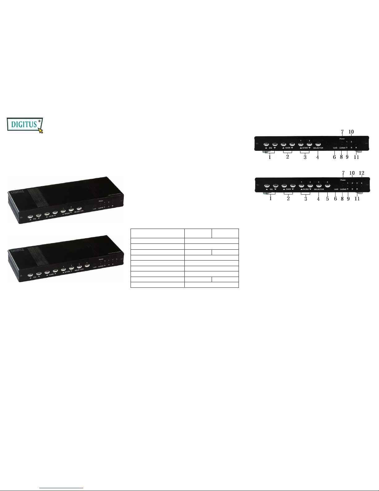
FRONT VIEW
DC-44400
DC-45400
1. EQ up/down button: Adjusts the equalization length
while in adjust mode adjust to sharpen weak images.
This will not work in general mode.
2. GAIN up/down button: Adjusts brightness in
adjustment mode. This will not work in general mode.
3. Port 1, 2 button: Selection key for Ports 1 and 2 while
in general mode.
RGB SKEW up/down button: Can only be adjusted
while in adjust mode.
4. Port 3 button: Selection key for Port 3 while in general
mode.
SELECTOR button: Selection key for R, G or B SKEW
while in adjust mode.
*While in DC-44400, this is the selection key for RGB
SKEW in adjust mode. Does not work in general
mode.
5. Port 4 button: Selection key for PORT 4 while in
general mode. Does not work in adjust mode.
*While in DC-44400 do not press this key.
6. Lock button: Press Lock key. Locked LED will power
down. Next, enter adjust mode. Press the lock key
once more, and the Locked LED will light up. Then
return to general mode. Your data will be saved after
the adjustment.
7. Power LED
8. Locked LED: Locked LED is off. Enter adjust mode.
Locked LED is on. Return to general mode.
9. Port 1 LED: This is the Port 1 LED while in general
mode. LED blinks when selected.
R LED: While in RGB SKEW selection mode
outputting to R selection mode, the LED will be lit.
-2-
Page 2
10. Port 2 LED: This is the PORT 2 LED while in general
mode. This LED blinks when selected.
G LED: While in RGB Skew selection mode, and while
in G selection mode, the LED is lit.
11. Port 3 LED: LED for PORT 3 while in general mode.
LED blinks when selected.
B LED: While in RGB SKEW adjust mode outputting to
B adjust mode, the LED will be lit.
*While in DC-44400, this LED will not light up in
general mode, but will light up in adjust mode.
12. Port 4 LED
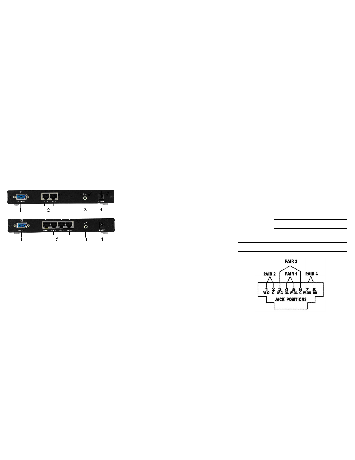
REAR VIEW
DC-44400
DC-45400
1. VGA Output
2. RJ-45 Input
3. Audio Output
4. Power Jack
-3-
Installation
1. Connect the VGA-Extender or AV-Extender local unit
RJ-45 output connector and DC-44400/DC-45400 RJ-45
Input connect with CAT.5 cables.
2. Connect the DC-44400/DC-45400 VGA output
connector with HD-15 male to male cable from monitor.
3. Connect the DC-44400/DC-45400 audio output
connector with audio cable from audio amplifier
.
4. EQ and GAIN compensates the loss caused by the
length of the cable, and the VGA output can be
connected to a monitor to view the image quality.
Note: Excessive EQ and GAIN compensation may cause
incorrect decoding, abnormal display, or no display at all.
Operation
General Mode:
After turning on the power, the power LED and locked
LED will light up, the Port 1 LED will blink, and the rest
of the LEDs will be off.
When a Port's selection key is selected, the
corresponding LED will blink; the Lock key also can be
used to operate adjust mode, while the remaining keys
are non-functional.
A. Adjust Mode:
In normal mode, after selecting Port 1, 2, 3 or 4, press the
Lock key to enter Port adjustment mode. Once the
adjustment is complete, press the Lock key again to exit
Port adjustment mode. Next, save the port adjustment
data and return to normal mode.
Press the Lock key. All of the LEDs will shut off except
for the Power LED. Enter adjust mode.
Pressing the EQ up/down button will adjust the
definition, while pressing both buttons at once returns to
zero.
Pressing the GAIN up/down button will adjust the
brightness, while pressing both buttons at once returns
to zero.
Press the SELECTOR button to choose R, B or G
SKEW adjustment. The selected R, G or B LED will light
up.
A lit R LED indicates that pressing the SKEW up/down
button will adjust the delay time for R. Pressing both
buttons as once returns to zero.
-4-
When the G LED is on, it indicates that pressing the
SKEW up/down button will adjust the delay time for G.
Pressing both buttons and the same time returns to
zero.
When the B LED is lit, it indicates that the SKEW
up/down button adjusts the delay time for B. Pressing
both buttons at the same time returns to zero.
Press the LOCK key when the adjustment is complete.
The Locked LED will light up. Exist adjustment mode,
return to general mode, and save post-adjustment data.
Note:
1. Pressing the EQ up/down button increases or decreases
voltage by 33mV, to a maximum of 1V.
2. Pressing the Gain up/down button increases or decreases the
voltage by 33mV, to a maximum of 1V.
3. Pressing the RGB SKEW up/down button increases or
decreases delay time by 2ns, to a maximum delay of 64ns.
Wiring Information & Coding
Conductor
Identification
RJ45 Pin
Assignment
Color Code for
Conductor
Pair 1
5 White-Blue
4 Blue
Pair 2
1 White-Orange
2 Orange
Pair 3
3 White-Green
6 Green
Pair 4
7 White-Brown
8 Brown
Trademarks:
All the companies, brand names, and product names
referred to this manual are the trademarks or registered
trademarks belonging to their respective companies.
-5-
 Loading...